This Nonprovisional application claims priority under 35 U.S.C. § 119(a) on Patent
Application No. 10-2003-0067935 filed in Korea on September 30, 2003, Application No.
10-2003-0089891 filed in Korea on December 10, 2004 and Application No. 10-2003-0089892
filed in Korea on December 10, 2004, the entire contents of which are hereby
incorporated by reference.
BACKGROUND OF THE INVENTION
Field of the Invention
The present invention relates to a plasma display panel, and more
particularly, to a method and apparatus for driving a plasma display panel.
Description of the Background Art
A Plasma display panel (hereinafter, referred to as "PDP") is adapted to
display an image by light-emitting phosphors with ultraviolet rays generated during
the discharge of an inert mixed gas such as He+Xe or He+Xe. This PDP can be
easily made thin and large, and it can provide greatly enhanced picture quality
with the recent development of the relevant technology. Particularly, a three-electrode
AC surface discharge type PDP has advantages of lower driving voltage
and longer product lifespan as a wall charge is accumulated on a surface in
discharging and electrodes are protected from sputtering caused by discharging.
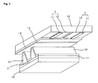
FIG. 1 is a perspective view illustrating the construction of a discharge cell
of a conventional three-electrode AC surface discharge type PDP. Referring now
to FIG. 1, the three-electrode AC surface discharge type PDP includes a plurality
of scan electrodes Y and a plurality of sustain electrodes Z which are formed on
the bottom surface of an upper substrate 10, and an address electrode X formed
on a lower substrate 18. The discharge cell of the PDP is formed at every crossing
of the scan electrodes Y, the sustain electrodes Z and the address electrodes X
and is arranged in a matrix form.
Each of the scan electrode Y and the sustain electrode Z includes a
transparent electrode 12, and a metal bus electrode 11 that has a line width
smaller than the transparent electrode 12 and is disposed at one side of the
transparent electrode. The transparent electrode 12, which is generally made of
ITO (indium tin oxide), is formed on the bottom surface of the upper substrate 10.
The metal bus electrode 11 is generally formed of a metal on the transparent
electrode 12 and serves to reduce a voltage drop caused by the transparent
electrode 12 having high resistance. On the bottom surface of the upper substrate
10 in which the scan electrodes Y and the sustain electrodes
are disposed is laminated an upper dielectric layer 13 and a
protective layer 14. The upper dielectric layer 13 is accumulated with a wall
charge generated during plasma discharging. The protective layer 14 is
adapted to prevent damages of the electrodes Y and Z and the upper
dielectric layer 13 due to sputtering caused during plasma discharging, and
improve efficiency of secondary electron emission. As the protective layer 14,
magnesium oxide (MgO) is generally used.
The address electrodes X are formed on the lower substrate 18 in the
direction that they intersect the scan electrodes Y and the sustain electrodes Z. A
lower dielectric layer 17 and a diaphragm 15 are formed on the lower substrate
18. A phosphor layer 16 is formed on the surface of the lower dielectric layer 17
and the diaphragm 15. The phosphor layer 16 is excited with ultraviolet rays
generated during the plasma discharging to generate any one visible light of red,
green and blue lights. An inert mixed gas such as He+Xe, Ne+Xe or He+Xe+Ne
for discharge is injected into the discharge space of the discharge cells provided
between the upper and lower substrates 10 and 18 and the diaphragm 15.
Such a three-electrode AC surface discharge type PDP is driven in such a
way that one frame is divided into several sub fields of different emission numbers
based on an address-display-separated sub field driving system. FIG. 2 shows a
conventional one frame containing eight time-divided sub fields. If an image is to
be represented using 256 gray levels, a frame period (16.67ms) corresponding to
1/60 second is divided into 8 sub fields SF1 to SF8, as shown in FIG. 2. Each of
the sub fields SF1 to SF8 is divided into a reset period for initializing a discharge
cell, an address period for selecting a discharge cell, and a sustain period for
implementing the gray level according to the number of discharge.
The reset period and the address period of each of the
sub fields SF1 to SF8 are the same in every sub fields, whereas the
sustain period and its discharge number increase in the ratio of 2n
(n=0,1,2,3,4,5,6,7) in each sub field.
The aforementioned PDP driving method causes picture quality to vary with
the order, weight and number of the sub fields. When the PDD driving method is
used, motion artifact, large area flicker and a variation in the number of visible
gray levels affect the picture quality. The motion artifact is caused by dynamic
false contour noise and motion blurring. The dynamic false contour noise appears
as a subfield-driven nonlinear emission pattern, and the motion blurring occurs
when light is emitted from pixels for a period of time loner than one frame period.
The dynamic false contour noise and the number of gray levels (the number of
sub fields) or the large area flicker and the motion blurring have a complementary
function relationship between them. For example, the motion blurring occurs when
a frame frequency is increased in order to reduce flicker whereas sever flicker is
generated when the frame frequency is decreased in order to reduce the motion
blurring.
Recently, some PDP manufacturers have attempted to improve picture
quality deterioration such as the dynamic false contour noise, large area flicker
and so on by rearranging sub fields and modulating the frame frequency from
50Hz to 100Hz as shown in FIG. 3. In FIG. 3, the vertical axis represents a weight
given to each sub field and the horizontal axis represents time. When the
method shown in FIG. 3 is employed, large area flicker generated at 50Hz can
be reduced and an emission pattern can be dispersed
with a 100Hz driving method to decrease the dynamic false
contour noise. However, the address period and the sustain period become short
seriously as resolution is increased to WVGA, XGA or HD resolution so that it is
impossible to arrange sub fields at 100Hz.
Another method for reducing flicker is to make the optical center of the
maximum brightness uniform in every frame when the optical center of the
maximum brightness is varied with frames in a sub frame array in which weights
are linearly arranged. However, this method requires a complicated algorithm and
circuit for calculations for making the optical center uniform in every frame.
Furthermore, there is an attempt to remove the dynamic false contour noise
using a method of increasing the number of sub fields while varying a panel
luminance or a method of increasing the number of sub fields without varying the
panel luminance in such a manner that the address period and vertical resolution
are exchanged. In this case, however, there is a limitation in increasing the
number of sub fields when the resolution of PDP is increased. Furthermore, a
vertical data component may be lost due to bit line repeat of a pre-filter.
SUMMARY OF THE INVENTION
Accordingly, an object of the present invention is to solve at least the
problems and disadvantages of the background art.
An object of the present invention is to provide a method and apparatus for
driving a PDP with high resolution, which can reduce large area flicker and
dynamic false contour noise.
According to a first embodiment of the present invention, there is provided
a method for driving a PDP including the steps of dividing two frame data items
into three frame data items; and providing the divided frame data items to the
PDP.
An apparatus for driving a PDP according to the first embodiment of the
present invention includes a frame converting unit for dividing two frame data
items into three frame data items; and a data providing unit for providing the
divided data items to the PDP.
According to second embodiment of the present invention, there is also
provided a method for driving a PDP including the steps of: writing nth frame data
(n is a natural number) in an odd-numbered line of a memory, writing (n+1)th
frame data in an even-numbered line of the memory, generating a single insertion
data item using data items read by addressing the odd-numbered line and even-numbered
line of the memory, and inserting the insertion data between the nth
frame data and the (n+1)th frame data; and providing the nth frame data, the
(n+1)th frame data and the insertion data to the PDP.
An apparatus for driving a PDP according to the second embodiment of the
present invention includes a memory including an odd-numbered line storing nth
frame data (n is a natural number) and an even-numbered line
storing (n+1)th frame data; a signal processor for generating a single insertion
data item using data items read by addressing the odd-numbered line and even-numbered
line of the memory and inserting the insertion data between the nth
frame data and the (n+1)th frame data; and a data providing unit for providing the
nth frame data, the (n+1)th frame data and the insertion data to the PDP.
According to a third embodiment of the present invention, there is provided
a method for driving a PDP including the steps of: storing (N-1)th frame data in a
frame memory; separating main object image data and background image data
from each of the stored (N-1)th frame data and Nth frame data currently input;
generating object image data of an insertion frame using the main object image
data of the (N-1)th frame data and the main object image data of the Nth frame
data; generating background image data of the insertion frame using the
background image data of the (N-1)th frame data and the background image data
of the Nth frame data; and synthesizing the main object image data and
background image data of the insertion frame to generate the insertion frame.
The method and apparatus for driving a PDP according to the present
invention can reduce large area flicker and dynamic false contour noise in a high-resolution
PDP.
BRIEF DESCRIPTION OF THE DRAWINGS
The invention will be described in detail with reference to the following
drawings in which like numerals refer to like elements.
FIG.1 is a perspective view illustrating the construction of a discharge cell
of a conventional three-electrode AC surface discharge type PDP.
FIG. 2 shows a conventional one frame containing eight time-divided sub
fields.
FIG. 3 shows a conventional 50Hz driving method.
FIG. 4 is a diagram for explaining a method of driving a PDP according to a
first embodiment of the present invention.
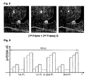
FIG. 5 shows input frame data items and an image of mean value data
inserted between the data items when the PDP driving method according to the
first embodiment of the present invention is applied to an experimental image.
FIG. 6 is a diagram for explaining a method of driving a PDP according to a
second embodiment of the present invention.
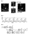
FIG. 7 shows input frame data items and an image of copy data inserted
between the data items when the PDP driving method according to the second
embodiment of the present invention is applied to an experimental image.
FIG. 8 is a diagram for explaining a method of driving a PDP according to
another embodiment of the present invention.
FIG. 9 is a block diagram of an apparatus for driving a PDP according to an
embodiment of the present invention.
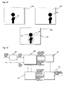
FIG. 10 shows a process of generating an insertion frame after an object is
detected according to a third embodiment of the present invention.
FIG. 11 shows a process of dividing frame data into a main object and a
background image.
FIG. 12 shows a process of generating an object of an insertion frame.
FIG. 13 is a block diagram showing a driving method for removing large
area flicker of a PDP.
FIG. 14 is a flow chart showing the driving method for removing large area
flicker of a PDP.
DETAILED DESCRIPTION OF PREFERRED EMBODIMENTS
Preferred embodiments of the present invention will be described in a more
detailed manner with reference to the drawings.
<First and second embodiments>
A method for driving a PDP according to a first embodiment of the present
invention includes the steps of dividing two frame data items into three frame data
items, and providing the divided frame data items to the PDP.
The two frame data items are input at a frame frequency of 50Hz.
The step of dividing the two frame data items includes a step of calculating
a mean value of the two frame data items and a step of inserting the mean value
between the two frame data items.
The step of dividing the two frame data items includes a step of copying
one of the two frame data items and a step of inserting the copied data between
the two frame data items.
The two frame data items include nth frame data and (n+1)th frame data (n
is a natural number larger than 1), and the method further includes a step of
mapping the (n+1)th frame data, the nth frame data and data inserted between
the nth and (n+1)th frame data to a sub field sequence including eight sub fields.
The two frame data items include nth frame data and (n+1)th frame data (n
is a natural number larger than 1), and the method further includes a step of
mapping the nth frame data to a sub field sequence including eight sub fields, a
step of mapping data inserted between the nth frame data and the (n+1)th frame
data to a sub field sequence including seven sub fields, and a step of mapping the
(n+1)th frame data to a sub field sequence including nine sub fields.
The two frame data items include nth frame data and (n+1)th frame data (n
is a natural number larger than 1), and the method further includes a step of
mapping the nth frame data to a sub field sequence including nine sub fields, a
step of mapping data inserted between the nth frame data and the (n+1)th
frame data to a sub field sequence including six sub fields, and a
step of mapping the (n+1)th frame data to a sub field sequence including nine sub
fields.
A method for driving a PDP according to a modified one of the first
embodiment of the present invention includes the steps of dividing five frame data
items into six frame data items, and providing the divided frame data items to the
PDP.
The five frame data items are input at a frame frequency of 50Hz.
The step of dividing the five frame data items includes a step of calculating
a mean value of two frame data items temporally adjacent to each other among
the five frame data items, and a step of inserting the mean value between the two
frame data items.
The step of dividing the five frame data items includes a step of copying
one of two frame data items temporally adjacent to each other among the five
frame data items, and a step of inserting the copied data between the two frame
data items.
An apparatus for driving a PDP according to the first embodiment of the
present invention includes a frame converting unit for dividing two frame data
items into three frame data items, and a data providing unit for providing the
divided data items to the PDP.
The two frame data items are input at a frame frequency of 50Hz.
The frame converting unit calculates a mean value of the two frame data
items and inserts the mean value between the two frame data items.
The frame converting unit copies one of the two frame data items and
inserts the copied data between the two frame data items.
The frame converting unit includes a synchronous detector for detecting a
frame frequency, a signal processor for inserting one of the mean value and the
copied data between the two frame data items when the frame frequency is 50Hz,
and a controller for controlling the signal processor in response to the frame
frequency.
An apparatus for driving a PDP according to the modified one of the first
embodiment of the present invention includes a frame converting unit for dividing
five frame data items into six frame data items, and a data providing unit for
providing the divided data items to the PDP.
The five frame data items are input at a frame frequency of 50Hz.
The frame converting unit calculates a mean value of two frame data items
temporally adjacent to each other among the five frame data items and inserts the
mean value between the two frame data items.
The frame converting unit copies one of two frame data items temporally
adjacent to each other and inserts the copied data between the two frame data
items.
The frame converting unit includes a synchronous detector for detecting a
frame frequency, a signal processor for inserting one of the mean value and the
copied data between the two frame data items when the frame frequency is 50Hz,
and a controller for controlling the signal processor in response to the frame
frequency.
A method for driving a PDP according to a second embodiment of the
present invention includes the steps of writing nth frame data (n is a natural
number) in an odd-numbered line of a memory, writing (n+1)th frame data in an
even-numbered line of the memory, generating a single insertion data item using
data items read by addressing the odd-numbered line and even-numbered line of
the memory, and inserting the insertion data between the nth frame data and the
(n+1)th frame data; and providing the nth frame data, the (n+1)th frame data and
the insertion data to the PDP.
The nth frame data and the (n+1)th frame data are input at a frame
frequency of 50Hz.
The insertion data is a copy of one of the odd-numbered line data and
even-numbered line data of the memory.
The insertion data is inserted between two frame data items adjacent to
each other among five frame data items input at the frame frequency of 50Hz.
An apparatus for driving a PDP according to the second embodiment of the
present invention includes a memory including an odd-numbered line storing nth
frame data (n is a natural number) and an even-numbered line storing (n+1)th
frame data; a signal processor for generating a single insertion data
item using data items read by addressing the odd-numbered line and
even-numbered line of the memory and inserting the insertion data between the
nth frame data and the (n+1)th frame data; and a data
providing unit for providing the nth frame data, the (n+1)th frame data and the
insertion data to the PDP.
The nth frame data and the (n+1)th frame data are input at a frame
frequency of 50Hz.
The signal processor copies one of the odd-numbered line data and even-numbered
line data of the memory to generate the insertion data.
The signal processor calculates a mean value of the odd-numbered line
data and even-numbered line data of the memory to generate the insertion data.
The signal processor inserts the insertion data between two frame data
items adjacent to each other among five frame data items input at the frame
frequency of 50Hz.
Hereafter, the first and second embodiments of the present invention will
now be explained in more detail with reference to the attached drawings.
Referring to FIGS. 4 and 5, the PDP driving method according to the first
embodiment of the present invention inserts new frame data corresponding to a
mean value of two frame data items, which are input during two frame periods
corresponding to 40ms, between the two frame data items when a frame
frequency is 50Hz to drive a PDP at pseudo 75Hz.
When the two frame data items include the nth frame data Fn and the
(n+1)th frame data Fn+1 (n is a natural number larger than 1), the frame data Fins
inserted between the nth frame data and the (n+1)th frame data corresponds
to the mean value of the temporally continuous two frame data
items. That is, when the first frame data is 1 st Fr. and the second frame data is
2nd Fr., the inserted frame data Fins is calculated by (1st Fr. + 2nd Fr.)/2.
When the three frame data items including the frame data corresponding to
the mean value are arranged for two frame periods when the PDP is driven at
50Hz, light is dispersed and thus large area flicker and dynamic false contour
noise can be reduced and the address period and sustain period of the high-resolution
PDP can be secured.
Referring to FIGS. 6 and 7, the PDP driving method according to the
second embodiment of the present invention copies one of two frame data items
that are input during two frame periods corresponding to 40ms at a frame
frequency of 50Hz and inserts the copied data between the two frame data items
to drive the PDP at pseudo 75Hz.
When it is assumed that the two frame data items include the nth frame
data Fn and the (n+1)th frame data Fn+1, the frame data inserted between the nth
frame data and the (n+1)th frame data is identical to the nth frame data or the
(n+1)th frame data. That is, during the two frame periods corresponding to 40ms,
the nth frame data, the (n+1)th frame data or the nth frame data, and the (n+1)th
frame data are sequentially provided to the PDP.
When one frame data is inserted between the two frame data items at the
frame frequency of 50Hz to drive the PDP at the pseudo 75Hz as described in the
above-described embodiments, it is preferable that the number of
sub fields of the continuous three frame data items is 8-8-8, 8-7-9
or 9-6-9 considering the large area flicker and dynamic false contour noise. The
following tables 1, 2 and 3 represent examples of the number of sub fields and
weights when the PDP is driven at the pseudo 75Hz.
| | SF1 | SF2 | SF3 | SF4 | SF5 | SF6 | SF7 | SF8 |
| Nth data | 1 | 2 | 4 | 8 | 16 | 46 | 46 | 47 |
| Insertion data | 1 | 2 | 4 | 8 | 16 | 46 | 46 | 47 |
| (n+1)th data | 1 | 2 | 4 | 8 | 16 | 46 | 46 | 47 |
In Table 1, each of the nth frame data Fn, the insertion data Fins (Fn or
Fn+1) and the (n+1)th frame data Fn+1 is mapped to eight sub fields to which
weights 1, 2, 4, 8, 16, 46, 46 and 47 are respectively given.
| | SF1 | SF2 | SF3 | SF4 | SF5 | SF6 | SF7 | SF8 | SF9 |
| Nth data | 1 | 2 | 4 | 8 | 16 | 46 | 46 | 47 |
| Insertion data | 1 | 2 | 4 | 8 | 16 | 46 | 46 |
| (n+1)th data | 1 | 2 | 4 | 8 | 16 | 46 | 46 | 47 | 47 |
In Table 2, the nth frame data Fn is mapped to eight sub fields to which
weights 1, 2, 4, 8, 16, 46, 46, and 47 are given, and the insertion data Fins (Fn or
Fn+1) is mapped to seven sub fields to which
weights 1, 2, 4, 8, 16, 46 and 46 are
given. The (n+1)th frame data Fn+1 are mapped to nine sub fields to which
weights 1, 2, 4, 8, 16, 46, 46, 47 and 47 are given.
| | SF1 | SF2 | SF3 | SF4 | SF5 | SF6 | SF7 | SF8 | SF9 |
| Nth data | 1 | 2 | 4 | 8 | 16 | 23 | 46 | 46 | 47 |
| Insertion data | | 2 | 4 | 8 | 16 | 46 | 46 |
| (n+1)th data | 1 | 3 | 4 | 8 | 16 | 24 | 46 | 46 | 47 |
In Table 3, the nth frame data Fn is mapped to nine sub fields to which
weights 1, 2, 4, 8, 16, 23, 46, 46, and 47 are given, and the insertion data Fins (Fn
or Fn+1) is mapped to six sub fields to which weights 2, 4, 8, 16, 46 and 46 are
given. The (n+1)th frame data Fn+1 are mapped to nine sub fields to which
weights 1, 2, 4, 8, 16, 24, 46, 47 and 47 are given.
In Tables 1, 2 and 3, the weights can be varied with the composition of a
discharge gas and a PDP model.
| | SF1 | SF2 | SF3 | SF4 | SF5 | SF6 | SF7 | SF8 |
| Nth data | 1 | 4 | 8 | 16 | 24 | 25 | 30 | 30 |
| Insertion data | 1 | 4 | 8 | 16 | 24 | 25 | 30 | 30 |
| (n+1)th data | 1 | 4 | 8 | 16 | 24 | 25 | 30 | 30 |
In Table 4, each of the nth frame data Fn, the insertion data Fins and the
(n+1)th frame data Fn+1 is mapped to eight sub fields to which
weights 1, 4, 8, 16,
24, 25, 30 and 30 are respectively given.
| | SF1 | SF2 | SF3 | SF4 | SF5 | SF6 | SF7 | SF8 | SF9 |
| Nth data | 1 | 4 | 8 | 16 | 24 | 25 | 30 | 30 |
| Insertion data | 1 | 4 | 8 | 16 | 24 | 25 | 30 |
| (n+1)th data | 1 | 4 | 8 | 16 | 24 | 25 | 30 | 30 | 30 |
In Table 5, the nth frame data Fn is mapped to eight sub fields to which
weights 1, 4, 8, 16, 24, 25, 30 and 30 are given, and the insertion data Fins (Fn or
Fn+1) is mapped to seven sub fields to which
weights 1, 4, 8, 16, 24, 25 and 30
are given. The (n+1)th frame data Fn+1 are mapped to nine sub fields to which
weights 1, 4, 8, 16, 24, 25, 30, 30 and 30 are given.
| | SF1 | SF2 | SF3 | SF4 | SF5 | SF6 | SF7 | SF8 | SF9 |
| Nth data | 1 | 4 | 8 | 16 | 24 | 25 | 30 | 30 | 30 |
| Insertion data | 1 | 4 | 8 | 16 | 24 | 25 |
| (n+1)th data | 1 | 4 | 8 | 16 | 24 | 25 | 30 | 30 | 30 |
In Table 6, the nth frame data Fn is mapped to nine sub fields to which
weights 1, 4, 8, 16, 24, 25, 30, 30 and 30 are given; and the insertion data Fins
(Fn or Fn+1) is mapped to six sub fields to which weights 1, 4, 8, 16, 24 and 25.
The (n+1)th frame data Fn+1 are mapped to nine sub fields to which weights 1, 4,
8, 16, 24, 25, 30, 30 and 30 are given.
In Tables 1 to 6, the weights can be varied with the composition of a
discharge gas or a PDP model.
A selective write/erase method can be applied to a cell selecting method
and sub field arrangement. The selective write/erase method is more
advantageous for high speed driving than a selective write method that selects an
on-cell from a part of sub fields included in one frame and selects an
off-cell from the other sub fields to thereby select only the on-cell and
a selective erase method that selects only an off-cell from sub fields. Thus, the
selective write-erase method is suitable for a PDP with high resolution and
produces higher contrast and luminance. In the case where frame data is inserted
between two frame data items at the frame frequency of 50Hz to drive a PDP at
the pseudo 75Hz using the selective write/erase method, it is preferable that the
number of sub fields of the continuous three frame data items is 8-8-8, 8-7-9 or 9-6-9
considering the large area flicker and dynamic false contour noise.
Referring to FIG. 8, the PDP driving method according to the second
embodiment of the present invention inserts data corresponding to a mean value
of previous frame data and next frame data into a predetermined position during
five frame periods corresponding to 100ms at the frame frequency of 50Hz or
repeatedly provides one of the previous frame data and the next frame data to a
PDP, to thereby drive the PDP at pseudo 60Hz.
Assume nth, (n+1)th, (n+2)th, (n+3)th and (n+4)th frame data items which
are temporally continuous. Data corresponding to a mean value of two frame data
items continuously input during 100ms or a copy of one of the two frame data
items is inserted between the two frame data items. For instance, the inserted
data can be a mean value of the second frame data 2nd Fr. and the third frame
data 3rd Fr. or a copy of one of the second and third frame data items 2nd Fr. and
3rd Fr., and it is inserted between the second and third frame data items, as
shown in FIG. 8.
When the data corresponding to the mean value of the continuous two
frame data items or the copy of the one of the two frame data items is inserted
into a predetermined position in the frame data sequence such that the PDP is
driven at pseudo 60Hz, light is dispersed and thus the large area flicker and
dynamic false contour noise are reduced. Furthermore, the address period and
sustain period of a PDP with high resolution is easily secured.
FIG. 9 is a block diagram of an apparatus for driving a PDP according to an
embodiment of the present invention. The PDP driving apparatus includes a
synchronous detector 91, a timing controller 92, a signal processor 93, frame
memories 94a and 94b, a data arrangement unit 95, and buffers 96a and 96b.
The synchronous detector 91 counts a vertical synchronous signal V and a
horizontal synchronous signal H in response to a clock signal CLK to detect a
frame frequency and provides the frame frequency to the timing controller 92.
The signal processor 93 carries out error diffusion, gain control and
dithering for digital video data RGB under the control of the timing controller 92,
maps the digital video data to predetermined sub fields bit by bit, and then
provides the mapped data to the data arrangement unit 95. When the frame
frequency is 60Hz, the signal processor 93 stores the digital video data RGB in
the frame memories 94a and 94b frame by frame under the control of the timing
controller 92, and then reads the data stored in the frame memories
94a and 94b. Then, the signal processor 93 carries out error
diffusion, gain control and dithering for the read data and maps the data to twelve
sub fields to which weights 1, 2, 4, 8, 16, 32, 32, 32, 32, 32, 32 and 32 are
respectively given in a data input order. When the frame frequency is 50Hz, the
signal processor 93 stores digital video data RGB of the nth frame Fn in the first
frame memory 94a and stores digital video data RGB of the (n+1)th frame in the
second frame memory 94b under the control of the timing controller 92. Then, the
signal processor inserts data corresponding to a mean value of the nth and
(n+1)th frame data items or a copy of one of the nth and (n+1)th frame data items
between the nth and (n+1)th frame data items or inserts the mean data or copy
data into a predetermined position in five frame data items continuously input as
described in the aforementioned embodiments.
The timing controller 92 controls the signal processor 93 in response to the
frame frequency detected by the synchronous detector 91. Specifically, the timing
controller 92 controls the signal processor 93 such that the signal processor 93
maps digital video data RGB to predetermined sub fields in the order of inputting
the digital video data RGB when the frame frequency is 60Hz. When the frame
frequency is 50Hz, the timing controller 92 controls the signal processor 93 such
that the signal processor 93 inserts frame data between two continuous frame
data items or insert frame data into a predetermined position in continuous five
frame data items.
The data arrangement unit 95 temporarily stores data received from the
signal processor 93 in the buffers 96a and 96b, and then provides data read from
the buffers 96a and 96b to a data driving circuit chip of a PDP 97.
As described above, the method and apparatus for driving a PDP
according to the first embodiment of the present invention can disperse light in a
PDP with high resolution to reduce the large area flicker and dynamic false
contour noise.
Furthermore, the method and apparatus for driving a PDP according to the
second embodiments of the present invention write the nth frame data in odd-numbered
lines of a memory and write the (n+1)th frame data in even-numbered
lines of the memory, read odd-numbered line data of the memory and even-numbered
line data that is the closest to the odd-numbered line data, and
calculate a mean value of the read data items. Accordingly, a speed of calculating
the mean value of the frame data items for reducing the large area flicker and
dynamic false contour noise is reduced and thus the calculation can be efficiently
carried out.
<Third embodiment>
A method for driving a PDP according to the third embodiment of the
present invention includes the steps of storing (N-1)th frame data in a frame
memory; separating main object image data and background image data from
each of the stored (N-1)th frame data and Nth frame data currently input;
generating object image data of an insertion frame using the main object image
data of the (N-1)th frame data and the main object image data of the
Nth frame data; generating background image data of the insertion frame using
the background image data of the (N-1)th frame data and the background image
data of the Nth frame data; and synthesizing the main object image data and
background image data of the insertion frame to generate the insertion frame.
The driving method further includes a step of displaying the (N-1)th frame,
a step of displaying the insertion frame, and a step of displaying the Nth frame.
The number N is selected from 1 through 50.
The frames are driven at a frequency of 75Hz.
Hereafter, the third embodiment of the present invention will now be
explained in more detail with reference to the attached drawings.
FIG. 10 shows a process of generating an insertion frame after objects are
detected according to the third embodiment of the present invention. The insertion
frame is generated by image reconstruction.
Referring to FIG. 10, only main objects 304 and 305 are extracted from (N-1)th
and Nth frames 301 and 302. A main object image of the insertion frame is
reconstructed using the extracted main object images.
Then, a background image of the insertion frame is generated using
background images of the (N-1)th and Nth frames 301 and 302.
The insertion frame 303 is generated using the generated object image and
background image of the insertion frame. That is, the third embodiment of
the present invention generates a new image by combining the extracted
data in order to make the insertion frame for up-converting 50Hz to 75Hz,
distinguished from a prior art that simply combines two data items to insert a
blurred image. When the newly generated frame is inserted, a smooth motion can
be represented and picture quality can be improved.
FIG. 11 shows a process of dividing frame data into a main object and a
background image, and FIG. 12 shows a process of generating an object of an
insertion frame. Referring to FIGS. 11 and 12, an input frame 301 is divided into a
main object image 301a and a background image 301b. The (N-1)th object image
301a and the Nth object image 302a respectively separated from the (N-1)th
frame and the Nth frame are combined to generate an object image 303a of the
insertion frame. A background image 301b of the insertion frame is generated by
averaging background image data of the (N-1)th frame and background image
data of the Nth frame.
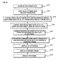
FIG. 13 is a block diagram showing a driving method for removing large
area flicker of a PDP, and FIG. 14 is a flow chart showing the driving method for
removing large area flicker of a PDP. The process of generating the insertion
frame will now be explained with reference to FIGS. 13 and 14.
The input (N-1)th frame data is stored in a frame memory 601 in the step
S701.
The (N-1)th frame data and the Nth frame data are input, and main object
image data of the (N-1)th frame data and main object image data of the Nth frame
data are detected in the step S702. The detected main object image
data and background image data are extracted in the step S703. As a
method of detecting the main object image data, the conventional gradient
watershed algorithm or region growing image processing algorithm is preferably
used. When the object image is detected and extracted from each frame using the
algorithm, the main object image data and background image data are separated
from each of the (N-1)th frame data and the Nth frame data.
Then, a main object image of the insertion frame is generated in the step
S704. The main object image data of the (N-1)th frame and the main object image
data of the Nth frame, separated in the step S703, are combined by the following
method.
The main object image data of the Nth frame is compared with the main
object image data of the (N-1)th frame. A common value among the main object
image data values of the two frames is used as it is for constructing the main
object image of the insertion frame. Among the main object image data values of
the two frames, a difference value between main object image data values of the
two frames is not used. Instead an intermediate value of the corresponding main
object image data values of the two frames is used for constructing the main
object image of the insertion frame.
The reconstructed data generates the main object image of the insertion
frame as shown in FIG. 12.
In the step S705, the background image of the insertion frame is
generated. A method of generating the background image of the insertion
frame is different from the method of generating the main object image of the
insertion frame in the step S704. That is, the background image data of the
insertion frame is generated using the background image data of the (N-1)th
frame and the background image data of the Nth frame. Since there is a little
difference between the background image data of the (N-1)th frame and the
background image data of the Nth frame, a value obtained by adding up the two
background image data values and dividing the added value by half can be used
or a blurred image obtained by simply adding up the two background image data
items can be used.
In the step S706, the insertion frame is generated by synthesizing the main
object image data of the insertion frame, generated in the step S704, and the
background image data of the insertion frame, generated in the step S705. That
is, the object image and background image of the insertion frame are synthesized
to accomplish one insertion frame image.
In the steps S707, S708 and S709 for displaying frames, the generated
insertion frame is inserted between the (N-1)th frame and the Nth frame.
For up-converting a frame frequency to 75Hz, the number N can be
selected from odd numbers. That is, the first and second frames generate one
insertion frame and the third and fourth frames generate one insertion frame. This
is repeated until the forty-ninth and fiftieth frames generate one insertion frame. In
this manner, twenty-five insertion frames are generated. Accordingly, the total
number of frames can be 75.
The number N is not limited to odd numbers and it can be an even number.
The 75Hz up-conversion is an example and any up-conversion can be
achieved. That is, it is possible to generate insertion frames based on a desired
number of frames.
In general, when a PDP is driven in W-VGA, twenty-four sub fields are
used for two frames because twelve sub fields are used for one frame. When
these two frames are divided into three frames, the PDP can be driven using
SW8-SW8-SW8/SW8-SW7-SW9/SW9-SW6-SW9 method or SWSE-combined8-8-8/8-7-9/9-6-9
method.
For example, when the PDP is driven in 8-8-8 SF structure, the insertion
frame is generated using the method provided by the present invention and then
an image is represented with eight sub fields.
As described above, the present invention can remove large area flicker
generated when a 50Hz video signal such as PAL or SECAM is input in a PDP or
a digital micro-mirror device panel. Furthermore, the present invention can be
applied to light-emitting devices such as a digital micro-mirror device in addition to
the PDP.
The invention being thus described, it will be obvious that the same may be
varied in many ways. Such variations are not to be regarded as a departure from
the spirit and scope of the invention, and all such modifications as would be
obvious to one skilled in the art are intended to be included within the scope of the
following claims.
The claims refer to examples of preferred embodiments of the invention.
However, the invention also refers to the use of any single feature and
subcombination of features which are disclosed in the claims, the description
and/or the drawings.