EP1521165A2 - Verfahren und Vorrichtung zur Datenumwandlung, und Lagemessungsgerät - Google Patents
Verfahren und Vorrichtung zur Datenumwandlung, und Lagemessungsgerät Download PDFInfo
- Publication number
- EP1521165A2 EP1521165A2 EP04255987A EP04255987A EP1521165A2 EP 1521165 A2 EP1521165 A2 EP 1521165A2 EP 04255987 A EP04255987 A EP 04255987A EP 04255987 A EP04255987 A EP 04255987A EP 1521165 A2 EP1521165 A2 EP 1521165A2
- Authority
- EP
- European Patent Office
- Prior art keywords
- coordinate system
- orientation
- sensor
- data
- reference coordinate
- Prior art date
- Legal status (The legal status is an assumption and is not a legal conclusion. Google has not performed a legal analysis and makes no representation as to the accuracy of the status listed.)
- Granted
Links
Images


Classifications
-
- G—PHYSICS
- G06—COMPUTING OR CALCULATING; COUNTING
- G06F—ELECTRIC DIGITAL DATA PROCESSING
- G06F3/00—Input arrangements for transferring data to be processed into a form capable of being handled by the computer; Output arrangements for transferring data from processing unit to output unit, e.g. interface arrangements
- G06F3/01—Input arrangements or combined input and output arrangements for interaction between user and computer
- G06F3/011—Arrangements for interaction with the human body, e.g. for user immersion in virtual reality
- G06F3/012—Head tracking input arrangements
-
- G—PHYSICS
- G01—MEASURING; TESTING
- G01C—MEASURING DISTANCES, LEVELS OR BEARINGS; SURVEYING; NAVIGATION; GYROSCOPIC INSTRUMENTS; PHOTOGRAMMETRY OR VIDEOGRAMMETRY
- G01C21/00—Navigation; Navigational instruments not provided for in groups G01C1/00 - G01C19/00
- G01C21/20—Instruments for performing navigational calculations
-
- G—PHYSICS
- G01—MEASURING; TESTING
- G01C—MEASURING DISTANCES, LEVELS OR BEARINGS; SURVEYING; NAVIGATION; GYROSCOPIC INSTRUMENTS; PHOTOGRAMMETRY OR VIDEOGRAMMETRY
- G01C9/00—Measuring inclination, e.g. by clinometers, by levels
Definitions
- the present invention relates to a technique for measuring the orientation of an object using an orientation sensor.
- An image display apparatus which presents mixed reality is implemented by an apparatus which superimposes an image of a virtual space (e.g., a virtual object, text information, and the like rendered by computer graphics) onto an image of a physical space captured by an image sensing device such as a video camera or the like.
- a virtual space e.g., a virtual object, text information, and the like rendered by computer graphics
- orientation sensors As typical orientation sensors used in such method, TISS-5-40 (TOKIMEC INC.) and InertiaCube2 (InterSense Inc.) are available. Each of these orientation sensors mainly comprises gyro sensors for detecting angular velocities in triaxial directions, and acceleration sensors for detecting accelerations in the triaxial directions, and measures the triaxial orientation values (azimuth angle, pitch angle, roll angle) as a combination of these measurement values. In general, angle information obtained by the gyro sensor alone is only a relative change in orientation with respect to an orientation at a given time. However, these orientation sensors are characterized in that the gravitational direction of the earth is measured using the acceleration sensors to obtain the absolute angles with reference to the gravitational direction as tilt angles (i.e., pitch and roll angles).
- Orientation measurement values output from the orientation sensor represent the orientation of the sensor itself on a sensor coordinate system defined by the sensor itself irrespective of a reference coordinate system.
- the sensor coordinate system is defined to have the gravitational direction (down direction) as a Z-axis, and a direction in front of a sensor upon initializing the sensor on an X-Y plane specified by this Z-axis as an X-axis, in case of, e.g., TISS-5-40 above.
- the sensor coordinate system is defined to have the gravitational direction (down direction) as a Z-axis, and a north direction indicated by a built-in geomagnetic sensor upon initializing the sensor on an X-Y plane specified by this Z-axis as an X-axis.
- the orientation measurement values of the orientation sensor do not normally indicate the orientation itself of an object to be measured (an image sensing device in case of an image display apparatus that presents mixed reality) on the reference coordinate system as information to be acquired.
- the orientation measurement values of the orientation sensor cannot be directly used as the orientation of the object to be measured on the reference coordinate system, and must undergo some kind of coordinate conversion. More specifically, coordinate conversion that converts the orientation of the sensor itself into that of the object to be measured, and coordinate conversion that converts the orientation of the object to be measured on the sensor coordinate system into that on the reference coordinate system are required.
- offset data data required to perform coordinate conversion that converts the orientation of the sensor itself into that of the object to be measured
- alignment data data required to perform coordinate conversion that converts the orientation of the object to be measured on the sensor coordinate system into that on the reference coordinate system
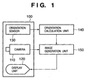
- Fig. 1 is a block diagram showing the arrangement of a general image display apparatus which presents mixed reality.
- a camera 110, display unit 120, and orientation sensor 130 are fixed to a head-mount unit 100.
- the orientation sensor 130 measures the orientation of the orientation sensor 130 itself on the sensor coordinate system, and outputs orientation measurement values of three degrees of freedom.
- the orientation sensor 130 comprises, e.g., TISS-5-40 or InertiaCube2.
- An orientation calculation unit 140 receives the orientation measurement values from the orientation sensor 130, applies coordinate conversion to the orientation measurement values in accordance with alignment data and offset data held by an internal memory (not shown) to calculate the orientation of the camera 110 on the reference coordinate system, and outputs it to an image generation unit 150 as orientation information.
- the image generation unit 150 generates a virtual image corresponding to the position and orientation of the camera 110 in accordance with the orientation information input from the orientation calculation unit 140 and position information of the camera 110 on the reference coordinate system, which is input from a position calculation unit (not shown: e.g., a receiver of a global positioning system), and outputs that image by superimposing it onto an actually captured image input from the camera 110.
- the display unit 120 receives the image output from the image generation unit 150, and displays it.
- an observer (not shown: i.e., a person who wears the head-mount unit 100) observes a composite image of the actually captured image (an image of the physical space) and virtual image (an image of the virtual space), which is displayed on the display unit 120 arranged in front of his or her eyes.
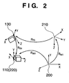
- R WV the orientation of the camera 110 on a reference coordinate system 200 (a coordinate system fixed to the physical space)
- R WT the orientation of a sensor coordinate system 210 on the reference coordinate system 200
- R TS the orientation of the orientation sensor 130 on the sensor coordinate system 210
- R SV the orientation of the camera 110 from the perspective of the orientation sensor 130
- R WT R WT ⁇ R TS ⁇ R SV
- R TS corresponds to the input data from the orientation sensor 130 to the orientation calculation unit 140
- R WV corresponds to the output data from the orientation calculation unit 140
- R SV corresponds to the offset data
- R WT corresponds to the alignment data.
- the orientation calculation unit 140 calculates R WV based on equation (A) using R TS input from the orientation sensor 130, and R SV and R WT held by the internal memory, and outputs it to the image generation unit 150.
- the value of the offset data R SV is always constant as long as the relative orientation relationship between the orientation sensor 130 and camera 100 remains the same.
- the offset data need only be derived only when the orientation sensor 130 and camera 100 are set on the head-mount unit 100.
- the offset data need only be derived only when the orientation sensor is set on the object to be measured.
- the value of the alignment data R WT is always constant as long as the relative orientation relationship between the reference coordinate system 200 and sensor coordinate system 210 remains the same, and the alignment data need only be derived only when the reference coordinate system 200 is defined.
- the sensor coordinate system 210 since the sensor coordinate system 210 is determined depending on the orientation of the orientation sensor 130 upon initializing the sensor, as described above, if the orientation of the orientation sensor 130 upon initializing the sensor differs, the sensor coordinate system 210 differs. In case of InertiaCube2, since the sensor coordinate system 210 is determined depending on the north direction indicated by the geomagnetic sensor upon initializing the sensor, the sensor coordinate system 210 may differ depending on a change in magnetic environment upon initializing the sensor.
- the definition of the sensor coordinate system 210 changes depending on the orientation, magnetic environment, and the like upon initializing the orientation sensor 130. Therefore, an appropriate value of the alignment data is not constant, and must be derived again every time the orientation sensor 130 is initialized. Since this conventional method facilitates derivation of the alignment data, the orientation can be accurately measured even when the sensor coordinate system 210 has changed.
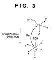
- an orientation sensor which can measure tilt angles as the absolute angles with reference to the gravitational direction has a feature that one of the axes of the sensor coordinate system 210 is set to agree with the gravitational direction (or its inverse direction).
- the Z-axis of the sensor coordinate system 210 is set to agree with the gravitational direction, as shown in Fig. 3.
- the Z-axis of the sensor coordinate system 210 indicates the gravitational direction.
- This conventional method limits the degrees of freedom in design of the reference coordinate system 200 so as to facilitate derivation of alignment data. More specifically, as shown in Fig. 3, only the orientation that can be expressed by rotating the sensor coordinate system 210 in the azimuth direction can be defined as that of the reference coordinate system 200. In other words, the condition that the gravitational direction must always be defined as the Z-axis of the reference coordinate system 200 is placed as a restriction upon designing the reference coordinate system 200.
- the alignment data R WT as data required to convert the orientation on the sensor coordinate system 210 into that on the reference coordinate system 200 can be expressed by a rotation matrix that expresses a rotation in the azimuth direction.
- alignment data R WT can be expressed by only one scalar quantity ⁇ WT that expresses the rotation angle about the Z-axis. That is, R WT is given by:
- the appropriate value of the alignment data is not constant, and must be re-derived every time the orientation sensor 130 is initialized.
- the alignment data is defined by only ⁇ WT , the value which must be re-derived every time the orientation sensor 130 is initialized is only one scalar quantity ⁇ WT .
- the value ⁇ WT held by the orientation calculation unit 140 need only be interactively increased/decreased via an input device (not shown) such as a joystick or the like to attain accurate registration between an actually captured image and virtual image while observing an image (formed by superposing the virtual image on the actually captured image) displayed on the display unit 120.
- an input device not shown
- This process can be done very easily since only one variable need only be changed, and the degree of freedom of a variable is 1.
- the conventional method allows accurate orientation measurement without placing any restriction that the orientation sensor 130 must always be initialized in the same orientation or magnetic environment, since re-derivation of alignment data is facilitated by limiting the degree of freedom in design of the reference coordinate system 200.
- An embodiment of the present invention allows easy re-derivation of alignment data without placing any restriction on design of a reference coordinate system.
- a data conversion method for converting orientation data on a sensor coordinate system defined by an orientation sensor into orientation data on a reference coordinate system, which is different from the sensor coordinate system characterized by comprising: a first setting step of setting first alignment data which represents a gravitational direction on the reference coordinate system; a second setting step of setting second alignment data indicating a difference angle in an azimuth direction between the sensor coordinate system and reference coordinate system; an input step of inputting orientation data on the sensor coordinate system; and a conversion step of converting the orientation data on the sensor coordinate system input in the input step into orientation data on the reference coordinate system on the basis of data which represents a gravitational direction on the sensor coordinate system, and the first and second alignment data.
- a data conversion method for converting orientation data on a sensor coordinate system defined by an orientation sensor into orientation data on a reference coordinate system characterized by comprising: a step of calculating a first coordinate conversion required to adjust a gravitational direction on the sensor coordinate system to a gravitational direction on the reference coordinate system on the basis of the gravitational direction on the reference coordinate system and the gravitational direction on the sensor coordinate system; a step of calculating a second coordinate conversion required to perform difference angle rotation in an azimuth direction between a coordinate value of the sensor coordinate system and the reference coordinate system to have the gravitational direction on the reference coordinate system as a rotation axis; an input step of inputting orientation data on the sensor coordinate system; and a conversion step of converting the orientation data on the sensor coordinate system input in the input step into orientation data on the reference coordinate system using the first and second coordinate conversions.
- a data conversion apparatus for converting orientation data on a sensor coordinate system defined by an orientation sensor into orientation data on a reference coordinate system, which is different from the sensor coordinate system, characterized by comprising: first setting means for setting first alignment data which represents a gravitational direction on the reference coordinate system; second setting means for setting second alignment data indicating a difference angle in an azimuth direction between the sensor coordinate system and reference coordinate system; input means for inputting orientation data on the sensor coordinate system; and conversion means for converting the orientation data on the sensor coordinate system input by the input means into orientation data on the reference coordinate system on the basis of data which represents a gravitational direction on the sensor coordinate system, and the first and second alignment data.
- a data conversion apparatus for converting orientation data on a sensor coordinate system defined by an orientation sensor into orientation data on a reference coordinate system, which is different from the sensor coordinate system, characterized by comprising: means for calculating a first coordinate conversion required to adjust a gravitational direction on the sensor coordinate system to a gravitational direction on the reference coordinate system on the basis of the gravitational direction on the reference coordinate system and the gravitational direction on the sensor coordinate system; means for calculating a second coordinate conversion required to perform difference angle rotation in an azimuth direction between a coordinate value of the sensor coordinate system and the reference coordinate system to have the gravitational direction on the reference coordinate system as a rotation axis; input means for inputting orientation data on the sensor coordinate system; and conversion means for converting the orientation data on the sensor coordinate system input by the input means into orientation data on the reference coordinate system using the first and second coordinate conversions.
- a program characterized by making a computer execute a data conversion method of the present invention or a computer readable storage medium storing that program.
- This embodiment will explain a case wherein the orientation measurement method is applied to an image display apparatus that presents mixed reality.
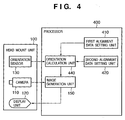
- Fig. 4 shows the apparatus arrangement of an image display apparatus in this embodiment.
- the image display apparatus of this embodiment adopts an arrangement having an orientation calculation unit 440 as a building component corresponding to the orientation calculation unit 140 in the image display apparatus shown in Fig. 1.
- First and second alignment data setting units 410 and 420 are added as building components. Note that the operations of the head-mount unit 100, camera 110, display unit 120, orientation sensor 130, and image generation unit 150 are the same as those in the image display apparatus shown in Fig. 1, and a description thereof will be omitted.
- an arrangement other than the head-mount unit 100 will be handled as a processor 400.
- the orientation calculation unit 440 holds, in its internal memory (not shown), first alignment data which represents the gravitational direction on the reference coordinate system 200, and second alignment data which represents a difference angle (a rotation angle about the axis of the gravitational direction (gravitational axis)) in the azimuth direction between the sensor coordinate system 210 and reference coordinate system 200. Also, the internal memory holds, as a known value, the coordinate conversion matrix R SV (i.e., offset data) required to convert the orientation of the orientation sensor 130 into that of the camera 110, since the relative orientation between the orientation sensor 130 and camera 110 remains the same.
- the orientation calculation unit 440 calculates the coordinate conversion matrix R WT , which has been explained using Fig. 2, using the first and second alignment data held by the internal memory. The practical configuration of the first and second alignment data, and the method of calculating R WT from the first and second alignment data will be described in detail later.
- the orientation calculation unit 440 further calculates R WV based on equation (A) using calculated R WT , R SV held by the internal memory, and R TS input from the orientation sensor 130, as in the orientation calculation unit 140, and outputs it to the image generation unit 150.
- the first alignment data setting unit 410 executes a process for reading out the first alignment data recorded in an external storage device (not shown), and setting it in the internal memory of the orientation calculation unit 440.
- the second alignment data setting unit 420 has a command input unit (not shown) that accepts a command input from an operator, and executes a process for changing the second alignment data value held in the internal memory of the orientation calculation unit 440 in accordance with the input command.
- orientation calculation unit 440, first and second alignment data setting unit 410 and 420, and image generation unit 150 which form the processor 400 in Fig. 4, may be configured as independent devices, or some or all of these units may be implemented by software to be executed by CPUs of one or a plurality of computers, thus implementing their functions.
- all of the respective units are implemented by software, and are executed in a single computer.
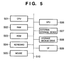
- Fig. 5 shows an example of the basic arrangement of a computer which implements the functions of the orientation calculation unit 440, first and second alignment data setting unit 410 and 420, and image generation unit 150 by executing software, and can be used as the processor 400.
- a CPU 501 controls the overall computer using programs and data stored in a RAM 502 and ROM 503, and serves as the orientation calculation unit 440, first and second alignment data setting unit 410 and 420, and image generation unit 150 by executing software programs that implement these units.
- the RAM 502 has an area for temporarily storing programs and data loaded from an external storage device 507 and storage medium drive 508, and a work area required for the CPU 501 to execute various processes.
- the RAM 502 serves as the internal memory (not shown) of the aforementioned orientation calculation unit 440.
- the ROM 503 stores software programs, which are generally executed by the computer upon startup, setting data, and the like.
- a keyboard 504 and mouse 505 are examples of the aforementioned input device (not shown), and the operator can input various instructions to the CPU 501 using these devices.
- the keyboard 504 and mouse 505 serve as the command input unit (to be described later) of the second alignment data setting unit 420.
- a GPU (Graphics Processing Unit) 506 is a processor used to execute a graphic process, and also has an image output function to a display device such as a CRT, liquid crystal monitor, or the like. In this embodiment, the GPU 506 outputs an image onto the display unit 120.
- the external storage device 507 serves as a large-capacity information storage device such as a hard disk or the like, and saves an OS (operating system), software programs which implement the orientation calculation unit 440, first and second alignment data setting units 410 and 420, and image generation unit 150, and the like.
- the external storage device 507 also saves information which will be described as known information in this embodiment.
- the storage medium drive 508 reads out programs and data stored in a removable storage medium such as a CD-ROM, DVD-ROM, or the like in accordance with an instruction from the CPU 501, and outputs them to the RAM 502 and external storage device 507.
- a removable storage medium such as a CD-ROM, DVD-ROM, or the like
- An I/F 509 is used to connect the orientation sensor 130 and camera 110, whose outputs are fetched by the RAM 502 via the I/F 508.
- a bus 510 interconnects the respective units in the computer.
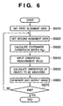
- Fig. 6 is a flowchart of the process of the image display apparatus in this embodiment, which is implemented by the CPU 501 by executing software programs. Assume that software programs for implementing the functions of the orientation calculation unit 440, first and second alignment data setting units 410 and 420, and image generation unit 150 have already been loaded from the external storage device 507, storage medium drive 508, and the like onto the RAM 502 prior to execution of the process shown in Fig. 6.
- the first alignment data setting unit 410 reads out the first alignment data saved in, e.g., a storage medium inserted into the storage medium drive 508, and sets its value in a predetermined variable defined on the RAM 502.
- the storage medium in the storage medium drive 508 pre-stores the value of the 3D vector gw according to the design of the reference coordinate system 200 as the first alignment data in the form of, e.g., a data file or the like according to a predetermined data format, and this value can be changed as needed.
- the second alignment data setting unit 420 changes the value of the second alignment data held in a predetermined variable defined on the RAM 502 in accordance with the input command in step S620.
- the second alignment data is formed of one scalar quantity ⁇ WT which represents a difference angle (a rotation angle about the axis of the gravitational direction (gravitational axis)) in the azimuth direction between the sensor coordinate system 210 and reference coordinate system 200.
- a command can be input by incrementing the value of ⁇ WT by a prescribed value (e.g., 1°) by clicking the right button of the mouse 505, by decrementing the value of ⁇ WT by the prescribed value by clicking the left button of the mouse 505, by directly inputting an increment/decrement of ⁇ WT using a ten-key pad of the keyboard 504, or the like.
- a prescribed value e.g. 1°
- the operator can interactively adjust the second alignment data using the mouse 505 or keyboard 504 while observing an adjustment image (an image formed by superimposing a virtual image onto an actually captured image) which is displayed on the display unit 120 by the image generation unit 150, so as to attain accurate registration between the actually captured image and virtual image.
- an adjustment image an image formed by superimposing a virtual image onto an actually captured image
- This process can be done very easily since the number of variables to be changed is one, and the degree of freedom of that variable is 1.
- step S620 Upon first execution of step S620, since a conversion R 1 (to be described later) required to display an adjustment image has not been calculated yet, the flow immediately advances to step S630 without checking, e.g., the presence/absence of a user's input.
- step S630 the orientation calculation unit 440 calculates the coordinate conversion matrix R WT required to convert the orientation on the sensor coordinate system 210 into that on the reference coordinate system 200 using the first and second alignment data held by the RAM 502. Details of this calculation process will be explained below.
- the orientation calculation unit 440 then calculates a coordinate conversion matrix R 1 that performs coordinate conversion having the normal vector n as a rotation axis and the angle ⁇ as a rotation angle. That is, the conversion R 1 is that between the gravitational direction gs of the sensor coordinate system and the gravitational direction gw of a world coordinate system. Since the calculation method of the coordinate conversion matrix when the rotation axis and rotation angle are given is known to those who are skilled in the art, a detailed description thereof will be omitted.
- the orientation calculation unit 440 calculates a coordinate conversion matrix R 2 that performs coordinate conversion having the first alignment data gw as a rotation axis and the second alignment data ⁇ WT as a rotation angle. Since the calculation method of the coordinate conversion matrix when the rotation axis and rotation angle are given is known to those who are skilled in the art, a detailed description thereof will be omitted.
- the coordinate conversion matrix R WT is calculated in step S630.
- step S640 the orientation calculation unit 440 receives an orientation measurement value R TS from the orientation sensor 130 via the I/F 509.
- step S650 the orientation calculation unit 440 calculates R WV (i.e., the orientation of the camera 110 on the reference coordinate system 200) based on equation (A) using R WT calculated in step S630, R TS input in step S640, and R SV held as a known value.
- R WV i.e., the orientation of the camera 110 on the reference coordinate system 200
- step S660 the image generation unit 150 receives an actually captured image from the camera 110 via the I/F 509, superimposes and renders a virtual image on this actually captured image on the basis of the orientation of the camera 110 calculated in step S650 and the position of the camera 110 input from position measurement means (not shown), and outputs a composite image.
- step S670 the CPU 501 checks the presence/absence of a program end instruction. If no end instruction is detected, the CPU 501 repeats the processes in step S620 and subsequent steps. If an end instruction is detected, the CPU 501 quits execution of the program.
- the first embodiment has explained a case wherein an orientation sensor such as TISS-5-40 or InertiaCube2 which as the gravitational direction as the Z-axis is used.
- an orientation sensor such as TISS-5-40 or InertiaCube2 which as the gravitational direction as the Z-axis is used.
- embodiments are not limited to the arrangement using such specific sensor, and the orientation measurement method can be applied to any other sensors as long as an orientation sensor has a sensor coordinate system which is set in association with the gravitational direction.
- orientation measurement method is applied to an image display apparatus that presents mixed reality and comprises an orientation sensor which is designed to have the gravitational direction as an axis other than the Z-axis.
- Fig. 7 shows the apparatus arrangement of an image display apparatus in this embodiment.
- the image display apparatus of this embodiment adopts an arrangement which has an orientation calculation unit 740 as a building component corresponding to the orientation calculation unit 440 in the image display apparatus shown in Fig. 4, and an orientation sensor 730 as a building component corresponding to the orientation sensor 130.
- a third alignment data setting unit 720 is added as a building component. Note that the operations of the head-mount unit 100, camera 110, display unit 120, image generation unit 150, and first and second alignment data setting units 410 and 420 are the same as those in the image display apparatus shown in Fig. 4, and a description thereof will be omitted.
- the orientation sensor 730 is designed to have the gravitational direction as an axis other than the Z-axis.
- the orientation sensor 730 measures the orientation of the orientation sensor 730 itself on the sensor coordinate system, and outputs orientation measurement values of three degrees of freedom. This embodiment will give the following explanation under the assumption that the gravitational direction on the sensor coordinate system of the orientation sensor 730 agrees with a -Y-axis.
- the orientation calculation unit 740 holds, in its internal memory, first alignment data indicating the gravitational direction on the reference coordinate system 200, and second alignment data ⁇ WT which represents a difference angle (a rotation angle about the axis of the gravitational direction (gravitational axis)) in the azimuth direction between the sensor coordinate system 210 and reference coordinate system 200, as in the orientation calculation unit 440.
- the internal memory holds, as a known value, the coordinate conversion matrix R SV (i.e., offset data) required to convert the orientation of the orientation sensor 730 into that of the camera 110, as in the orientation calculation unit 440.
- the orientation calculation unit 740 further holds third alignment data indicating the gravitational direction of the sensor coordinate system 210 in addition to these data.
- the orientation calculation unit 740 calculates the coordinate conversion matrix R WT using the first, second, and third alignment data held by the internal memory.
- the practical configuration of the third alignment data and the method of calculating R WT from the first, second, and third alignment data will be described in detail later.
- the orientation calculation unit 740 further calculates R WV based on equation (A) using calculated R WT , R SV held by the internal memory, and R TS input from the orientation sensor 130, as in the orientation calculation unit 440, and outputs it to the image generation unit 150.
- the third alignment data setting unit 720 executes a process for reading out the third alignment data recorded in an external storage device (not shown), and setting it in the internal memory of the orientation calculation unit 740.
- orientation calculation unit 740, first, second, and third alignment data setting unit 410, 420, and 720, and image generation unit 150 which form a processor 700 in Fig. 7, may be configured as independent devices, or some or all of these units may be implemented by software to be executed by CPUs of one or a plurality of computers, thus implementing their functions.
- all of the respective units (orientation calculation unit 740, first, second, and third alignment data setting unit 410, 420, and 720, and image generation unit 150) are implemented by software, and are executed in a single computer.
- a computer which implements the functions of the orientation calculation unit 740, first, second, and third alignment data setting unit 410, 420, and 720, and image generation unit 150 by executing software, and can be used as the processor 400, has the arrangement shown in Fig. 5 as in the first embodiment.
- Fig. 8 is a flowchart of the process of the image display apparatus in this embodiment, which is implemented by the CPU 501 by executing software programs.
- software programs for implementing the functions of the orientation calculation unit 740, first, second, and third alignment data setting units 410, 420, and 720, and image generation unit 150 have already been loaded from the external storage device 507, storage medium drive 508, and the like onto the RAM 502 prior to execution of the following process.
- steps (S610, S620, S640, S650, S660, S670) denoted by the same step numbers as those in Fig. 6 are the same as those in the first embodiment, and a description thereof will be omitted.
- the third alignment data setting unit 720 reads out the third alignment data saved in, e.g., a storage medium inserted into the storage medium drive 508, and sets its value in a predetermined variable defined on the RAM 502.
- the storage medium pre-stores the value of the 3D vector gs ((0, -1, 0) in this embodiment) according to the specification of the orientation sensor 730 as the third alignment data in the form of, e.g., a data file or the like according to a predetermined data format, and this value can be changed as needed.
- step S830 the orientation calculation unit 740 calculates the coordinate conversion matrix R WT required to convert the orientation on the sensor coordinate system 210 into that on the reference coordinate system 200 using the first, second, and third alignment data held by the RAM 502.
- the difference from step S630 is that the value gs is not held in advance in the RAM 502 as a known value, but is set by the third alignment data setting unit 720 in step S810, and other processing contents are the same as those in step S630.
- the orientation measurement apparatus and method of the present invention are applied to the image display apparatus that presents mixed reality.
- the orientation measurement apparatus and method can be used in various other applications that measure the orientation of an object using an orientation sensor.
- Fig. 9 shows an example of the apparatus arrangement of an orientation measurement apparatus according to this embodiment.
- the orientation measurement apparatus of this embodiment comprises a computer 900 and orientation sensor 130, which latter is the same as that in the first embodiment.
- the orientation sensor 130 is fixed to an arbitrary object 910 to be measured.
- the computer 900 has an orientation calculation unit 940 as a building component corresponding to the orientation calculation unit 440 in the first embodiment. Also, the computer 900 has first and second alignment data setting units 410 and 420 as building components as in the first embodiment.
- the orientation calculation unit 940 calculates the coordinate conversion matrix R WT from first and second alignment data set by the first and second alignment data setting unit 410 and 420, as in the orientation calculation unit 440. Furthermore, the orientation calculation unit 940 calculates an orientation R WV of the object 910 to be measured on the reference coordinate system on the basis of equation (A) using calculated R WT , R SV held by the internal memory, and R TS input from the orientation sensor 130, as in the orientation calculation unit 440.
- the orientation calculation unit 440 outputs the calculated orientation R WV to the image generation unit 150.
- the orientation calculation unit 940 outputs the calculated orientation R WV to an arbitrary device via an I/F (not shown).
- the orientation calculation unit 940 outputs the calculated orientation R WV to an arbitrary application program, which is running parallelly in the computer 900.
- another application generates and displays an adjustment image required to adjust the second alignment data.
- parameters required to adjust the second alignment data e.g., the calculated orientation R WV and the like are supplied to that application.
- the orientation of an object to be measured on the reference coordinate system can be acquired in various applications that measure the orientation of an object using an orientation sensor.
- the first alignment data setting unit 410 acquires the value of first alignment data to be set in a variable on the RAM 502 by reading out first alignment data saved in the storage medium drive 508.
- the method of acquiring the value of the first alignment data is not limited to such specific method.
- the value of the first alignment data may be acquired by directly coding that value in a software program used to implement the function of the first alignment data setting unit 410.
- the operator may input that value via the keyboard 504 or the like in step S610.
- the value may be stored in the external storage device 507, or may be acquired from another computer via a computer network.
- a computer independent from the orientation sensor 130 (730) comprises the orientation calculation unit 440 (740).
- the effect can be obtained when the orientation sensor 130 (730) itself or its auxiliary device has an equivalent function.
- the orientation sensor or its auxiliary device must have a function of receiving alignment data from required ones of the first to third alignment data setting units.
- the coordinate conversion matrix R 1 is calculated on the basis of the vector gw which is set as the first alignment data by the first alignment data setting unit 410 and indicates the gravitational direction on the reference coordinate system 200, and the vector gs which indicates the gravitational direction on the sensor coordinate system 210.
- the first alignment data need not always indicate the gravitational direction gw on the reference coordinate system 200.
- a calculation device that calculates the coordinate conversion matrix R 1 from the gravitational direction gw on the reference coordinate system 200 and the gravitational direction gs on the sensor coordinate system 210 may be independently available, and the first alignment data setting unit 410 may set the coordinate conversion matrix R 1 in the orientation calculation unit 440 as the first alignment data.
- the process for calculating the coordinate conversion matrix R 1 from gw and gs is omitted in step S630.
- a calculation device that calculates the rotation axis (normal vector) n and rotation angle ⁇ on the basis of the gravitational direction gw on the reference coordinate system 200 and the gravitational direction gs on the sensor coordinate system 210 may be independently available, and the first alignment data setting unit 410 may set the rotation axis n and rotation angle ⁇ in the orientation calculation unit 440 as the first alignment data.
- the process for calculating the rotation axis n and rotation angle ⁇ from the gravitational direction gw on the reference coordinate system 200 and the gravitational direction gs on the sensor coordinate system 210 is omitted in step S630.
- the orientation calculation unit supplies parameters (gs, gw) required in calculations to that device, and acquires the calculation result from that device.
- R 1 can be designated by another description method that can express a rotation matrix (e.g., Euler angle expression including roll, pitch, and yaw angles).
- a rotation matrix e.g., Euler angle expression including roll, pitch, and yaw angles.
- the aforementioned third embodiment has explained only the orientation measurement apparatus that uses the orientation measurement method described in the first embodiment. Also, the orientation measurement method described in the second embodiment can be similarly applied.
- the computer 900 includes the third alignment data setting unit 720.
- an embodiment includes a case wherein the equivalent functions are achieved by supplying a software program that implements the functions of the aforementioned embodiments (programs corresponding to one or more flowcharts shown in Figs. 6 and 8 in the embodiments) directly from a recording medium or using wired/wireless communications to a system or apparatus having a computer that can execute the program, and executing the supplied program by the computer of that system or apparatus.
- the program code itself supplied to and installed in the computer to implement the functional processes and a carrier (such as a storage medium or signal) carrying the program code constitute embodiments of the present invention.
- the form of program is not particularly limited, and an object code, a program to be executed by an interpreter, script data to be supplied to an OS, and the like may be used as along as they have the program function.
- the storage medium for supplying the program for example, magnetic recording media such as a flexible disk, hard disk, magnetic tape, and the like, optical/magnetooptical storage media such as an MO, CD-ROM, CD-R, CD-RW, DVD-ROM, DVD-R, DVD-RW, and the like, a nonvolatile semiconductor memory, and so forth may be used.
- a server on a computer network may store a data file (program data file), a compressed file including an automatic installation function, or the like, and the program data file may be downloaded to a client computer which establishes connection to the server.
- the program data file may be segmented into a plurality of segment files, which may be allocated on different servers.
- the server apparatus makes a plurality of users download the program data file for implementing the functional process of an embodiment on a computer.
- a storage medium such as a CD-ROM or the like, which stores the encrypted program may be delivered to the user, the user who has cleared a predetermined condition may be allowed to download key information that is used to decrypt the program from a home page via the Internet, and the encrypted program may be executed using that key information to be installed on a computer, thus implementing an embodiment.
- the functions of the aforementioned embodiments may be implemented not only by executing the readout program code by the computer but also by some or all of actual processing operations executed by an OS or the like running on the computer on the basis of an instruction of that program.
- the functions of the aforementioned embodiments may be implemented by some or all of actual processes executed by a CPU or the like arranged in a function extension board or a function extension unit, which is inserted in or connected to the computer, after the program read out from the recording medium is written in a memory of the extension board or unit.
- Embodiments may be achieved by supplying a storage medium (or recording medium), which records a program code of a software program that can implement the functions of the above-mentioned embodiments to a system or apparatus, and reading out and executing the program code stored in the storage medium by a computer (or a CPU or MPU) of the system or apparatus.
- the program code itself read out from the storage medium implements the functions of the above-mentioned embodiments
- the storage medium which stores the program code constitutes an embodiment.
- the functions of the above-mentioned embodiments may be implemented not only by executing the readout program code by the computer but also by some or all of actual processing operations executed by an operating system (OS) running on the computer on the basis of an instruction of the program code.
- OS operating system
Landscapes
- Engineering & Computer Science (AREA)
- Remote Sensing (AREA)
- Radar, Positioning & Navigation (AREA)
- Physics & Mathematics (AREA)
- General Physics & Mathematics (AREA)
- Theoretical Computer Science (AREA)
- General Engineering & Computer Science (AREA)
- Human Computer Interaction (AREA)
- Automation & Control Theory (AREA)
- Processing Or Creating Images (AREA)
- Length Measuring Devices By Optical Means (AREA)
- Controls And Circuits For Display Device (AREA)
- Studio Circuits (AREA)
- Studio Devices (AREA)
- Length Measuring Devices With Unspecified Measuring Means (AREA)
Applications Claiming Priority (2)
| Application Number | Priority Date | Filing Date | Title |
|---|---|---|---|
| JP2003341630 | 2003-09-30 | ||
| JP2003341630A JP4218952B2 (ja) | 2003-09-30 | 2003-09-30 | データ変換方法及び装置 |
Publications (3)
| Publication Number | Publication Date |
|---|---|
| EP1521165A2 true EP1521165A2 (de) | 2005-04-06 |
| EP1521165A3 EP1521165A3 (de) | 2007-10-03 |
| EP1521165B1 EP1521165B1 (de) | 2011-11-09 |
Family
ID=34309074
Family Applications (1)
| Application Number | Title | Priority Date | Filing Date |
|---|---|---|---|
| EP04255987A Expired - Lifetime EP1521165B1 (de) | 2003-09-30 | 2004-09-29 | Verfahren und Vorrichtung zur Orientierungsdatenumwandlung |
Country Status (4)
| Country | Link |
|---|---|
| US (1) | US7414596B2 (de) |
| EP (1) | EP1521165B1 (de) |
| JP (1) | JP4218952B2 (de) |
| CN (1) | CN1318942C (de) |
Cited By (2)
| Publication number | Priority date | Publication date | Assignee | Title |
|---|---|---|---|---|
| DE102008035440A1 (de) | 2008-07-25 | 2010-02-11 | Fraunhofer-Gesellschaft zur Förderung der angewandten Forschung e.V. | Vorrichtung und Verfahren zum Bestimmen der Entfernung und/oder Orientierung eines beweglichen Objekts |
| GB2540224A (en) * | 2015-07-08 | 2017-01-11 | Nokia Technologies Oy | Multi-apparatus distributed media capture for playback control |
Families Citing this family (46)
| Publication number | Priority date | Publication date | Assignee | Title |
|---|---|---|---|---|
| US8073157B2 (en) * | 2003-08-27 | 2011-12-06 | Sony Computer Entertainment Inc. | Methods and apparatus for targeted sound detection and characterization |
| US8797260B2 (en) | 2002-07-27 | 2014-08-05 | Sony Computer Entertainment Inc. | Inertially trackable hand-held controller |
| US8947347B2 (en) * | 2003-08-27 | 2015-02-03 | Sony Computer Entertainment Inc. | Controlling actions in a video game unit |
| US8233642B2 (en) | 2003-08-27 | 2012-07-31 | Sony Computer Entertainment Inc. | Methods and apparatuses for capturing an audio signal based on a location of the signal |
| US8160269B2 (en) | 2003-08-27 | 2012-04-17 | Sony Computer Entertainment Inc. | Methods and apparatuses for adjusting a listening area for capturing sounds |
| US9174119B2 (en) | 2002-07-27 | 2015-11-03 | Sony Computer Entertainement America, LLC | Controller for providing inputs to control execution of a program when inputs are combined |
| US8686939B2 (en) | 2002-07-27 | 2014-04-01 | Sony Computer Entertainment Inc. | System, method, and apparatus for three-dimensional input control |
| US8139793B2 (en) | 2003-08-27 | 2012-03-20 | Sony Computer Entertainment Inc. | Methods and apparatus for capturing audio signals based on a visual image |
| JP2005326275A (ja) * | 2004-05-14 | 2005-11-24 | Canon Inc | 情報処理方法および装置 |
| JP4227561B2 (ja) * | 2004-06-03 | 2009-02-18 | キヤノン株式会社 | 画像処理方法、画像処理装置 |
| US7852317B2 (en) | 2005-01-12 | 2010-12-14 | Thinkoptics, Inc. | Handheld device for handheld vision based absolute pointing system |
| KR101058032B1 (ko) * | 2005-04-01 | 2011-08-19 | 삼성전자주식회사 | 입체영상장치 |
| JP4773170B2 (ja) | 2005-09-14 | 2011-09-14 | 任天堂株式会社 | ゲームプログラムおよびゲームシステム |
| KR100827236B1 (ko) * | 2006-05-23 | 2008-05-07 | 삼성전자주식회사 | 포인팅 디바이스, 포인터 이동 방법 및 상기 포인터를디스플레이하는 디스플레이 장치 |
| JP4976756B2 (ja) | 2006-06-23 | 2012-07-18 | キヤノン株式会社 | 情報処理方法および装置 |
| US8913003B2 (en) | 2006-07-17 | 2014-12-16 | Thinkoptics, Inc. | Free-space multi-dimensional absolute pointer using a projection marker system |
| US20100184499A1 (en) * | 2007-02-01 | 2010-07-22 | Ritter Janice E | Electronic Game Device and Method of Using the Same |
| US20080188277A1 (en) * | 2007-02-01 | 2008-08-07 | Ritter Janice E | Electronic Game Device And Method Of Using The Same |
| US9176598B2 (en) | 2007-05-08 | 2015-11-03 | Thinkoptics, Inc. | Free-space multi-dimensional absolute pointer with improved performance |
| US20090062943A1 (en) * | 2007-08-27 | 2009-03-05 | Sony Computer Entertainment Inc. | Methods and apparatus for automatically controlling the sound level based on the content |
| US20090221368A1 (en) * | 2007-11-28 | 2009-09-03 | Ailive Inc., | Method and system for creating a shared game space for a networked game |
| TW200929014A (en) * | 2007-12-17 | 2009-07-01 | Omni Motion Technology Corp | Method that controls a controlled device by detecting movement of a hand-held control device, and the hand-held control device |
| JP4956456B2 (ja) | 2008-02-05 | 2012-06-20 | キヤノン株式会社 | 画像処理装置、画像処理方法 |
| CN101673312B (zh) * | 2008-09-08 | 2012-12-19 | 鸿富锦精密工业(深圳)有限公司 | 特征元素对齐方法 |
| JP5393318B2 (ja) * | 2009-07-28 | 2014-01-22 | キヤノン株式会社 | 位置姿勢計測方法及び装置 |
| KR101624505B1 (ko) * | 2009-09-24 | 2016-05-26 | 삼성전자주식회사 | 3-d 포인팅 감지 장치 및 방법 |
| CN102054461A (zh) * | 2009-11-09 | 2011-05-11 | 神基科技股份有限公司 | 电子装置显示器影像的呈像方向调节方法 |
| FR2976355B1 (fr) * | 2011-06-09 | 2013-06-21 | Jean Luc Desbordes | Dispositif de mesure de vitesse et de position d'un vehicule se deplacant le long d'une voie de guidage, procede et produit programme d'ordinateur correspondant. |
| US9355451B2 (en) | 2011-08-24 | 2016-05-31 | Sony Corporation | Information processing device, information processing method, and program for recognizing attitude of a plane |
| US10285141B1 (en) * | 2012-09-19 | 2019-05-07 | Safeco Insurance Company Of America | Data synchronization across multiple sensors |
| US20140123507A1 (en) * | 2012-11-02 | 2014-05-08 | Qualcomm Incorporated | Reference coordinate system determination |
| CN103307968B (zh) * | 2013-06-03 | 2016-11-02 | 西北工业大学 | 机器人承载平台姿态的检测方法 |
| JP6447514B2 (ja) * | 2013-12-25 | 2019-01-09 | ソニー株式会社 | 姿勢測定装置及び姿勢測定方法、画像処理装置及び画像処理方法、表示装置及び表示方法、コンピューター・プログラム、並びに画像表示システム |
| JP6525010B2 (ja) * | 2014-08-05 | 2019-06-05 | ソニー株式会社 | 情報処理装置及び情報処理方法、並びに画像表示システム |
| WO2016126672A1 (en) * | 2015-02-02 | 2016-08-11 | Brian Mullins | Head mounted display calibration |
| US9878447B2 (en) * | 2015-04-10 | 2018-01-30 | Microsoft Technology Licensing, Llc | Automated collection and labeling of object data |
| CN104748725B (zh) * | 2015-04-14 | 2017-05-17 | 北京经纬恒润科技有限公司 | 坡度测量方法及装置 |
| US10368059B2 (en) * | 2015-10-02 | 2019-07-30 | Atheer, Inc. | Method and apparatus for individualized three dimensional display calibration |
| EP3364150B1 (de) * | 2015-10-14 | 2024-04-24 | Alps Alpine Co., Ltd. | Wearable-vorrichtung, verfahren zur messung der ausrichtung davon und programm |
| JP7037560B2 (ja) * | 2016-11-16 | 2022-03-16 | マジック リープ, インコーポレイテッド | 低電力レンダリングを伴う複合現実システム |
| CN110267771A (zh) * | 2017-02-03 | 2019-09-20 | 三菱电机株式会社 | 变换系数计算装置、变换系数计算方法及变换系数计算程序 |
| CN107788991A (zh) * | 2017-10-26 | 2018-03-13 | 复旦大学 | 可穿戴式下肢康复评估系统 |
| JP7301514B2 (ja) * | 2018-09-21 | 2023-07-03 | 日立建機株式会社 | 座標変換システム及び作業機械 |
| CN111200745A (zh) * | 2019-12-31 | 2020-05-26 | 歌尔股份有限公司 | 视点信息采集方法、装置、设备和计算机存储介质 |
| CN114021231A (zh) * | 2021-10-28 | 2022-02-08 | 博锐尚格科技股份有限公司 | 一种测绘数据处理的方法、装置及电子设备 |
| JP2025045357A (ja) * | 2023-09-20 | 2025-04-02 | 株式会社Ihiインフラシステム | 3d計測システム並びにその基準軸方向算出方法及び基準軸方向算出用治具、3d計測システムにおける計測方法及び計測用治具 |
Family Cites Families (13)
| Publication number | Priority date | Publication date | Assignee | Title |
|---|---|---|---|---|
| DE19539367A1 (de) * | 1995-10-23 | 1997-04-24 | Siemens Ag | Verfahren zum Transformieren eines Koordinatensystems |
| ES2119697B1 (es) * | 1996-09-13 | 1999-04-16 | Infrarrojo Y Microelectronica | Fotosensor vectorial. |
| WO2001056007A1 (en) * | 2000-01-28 | 2001-08-02 | Intersense, Inc. | Self-referenced tracking |
| AU2002230578A1 (en) * | 2000-10-30 | 2002-05-15 | Naval Postgraduate School | Method and apparatus for motion tracking of an articulated rigid body |
| JP2002157607A (ja) * | 2000-11-17 | 2002-05-31 | Canon Inc | 画像生成システム、画像生成方法および記憶媒体 |
| CN1157650C (zh) * | 2001-01-16 | 2004-07-14 | 郭方红 | 用于计算机坐标与控制信息输入的系统及方法 |
| GB2376397A (en) * | 2001-06-04 | 2002-12-11 | Hewlett Packard Co | Virtual or augmented reality |
| JP3805231B2 (ja) | 2001-10-26 | 2006-08-02 | キヤノン株式会社 | 画像表示装置及びその方法並びに記憶媒体 |
| JP2003215494A (ja) * | 2002-01-22 | 2003-07-30 | Canon Inc | 複合現実感提示装置および画像処理方法 |
| CN1177256C (zh) * | 2002-04-30 | 2004-11-24 | 北京理工大学 | 基于多数字立体视觉头的物体完整表面三维恢复装置 |
| CN100398083C (zh) | 2002-08-30 | 2008-07-02 | 延自强 | 虚拟现实针灸穴位定位方法及系统 |
| EP1398601A3 (de) * | 2002-09-13 | 2014-05-07 | Canon Kabushiki Kaisha | Head-up-Anzeige für Navigationszwecke in einem Fahrzeug |
| JP2004127024A (ja) * | 2002-10-03 | 2004-04-22 | Canon Inc | 複合現実感システム用コンテンツ保護装置及び保護方法 |
-
2003
- 2003-09-30 JP JP2003341630A patent/JP4218952B2/ja not_active Expired - Fee Related
-
2004
- 2004-09-29 EP EP04255987A patent/EP1521165B1/de not_active Expired - Lifetime
- 2004-09-30 CN CNB200410081065XA patent/CN1318942C/zh not_active Expired - Fee Related
- 2004-09-30 US US10/952,876 patent/US7414596B2/en active Active
Cited By (2)
| Publication number | Priority date | Publication date | Assignee | Title |
|---|---|---|---|---|
| DE102008035440A1 (de) | 2008-07-25 | 2010-02-11 | Fraunhofer-Gesellschaft zur Förderung der angewandten Forschung e.V. | Vorrichtung und Verfahren zum Bestimmen der Entfernung und/oder Orientierung eines beweglichen Objekts |
| GB2540224A (en) * | 2015-07-08 | 2017-01-11 | Nokia Technologies Oy | Multi-apparatus distributed media capture for playback control |
Also Published As
| Publication number | Publication date |
|---|---|
| US7414596B2 (en) | 2008-08-19 |
| EP1521165A3 (de) | 2007-10-03 |
| EP1521165B1 (de) | 2011-11-09 |
| JP4218952B2 (ja) | 2009-02-04 |
| CN1604015A (zh) | 2005-04-06 |
| JP2005107248A (ja) | 2005-04-21 |
| US20050068293A1 (en) | 2005-03-31 |
| CN1318942C (zh) | 2007-05-30 |
Similar Documents
| Publication | Publication Date | Title |
|---|---|---|
| EP1521165B1 (de) | Verfahren und Vorrichtung zur Orientierungsdatenumwandlung | |
| US7092109B2 (en) | Position/orientation measurement method, and position/orientation measurement apparatus | |
| US6993451B2 (en) | 3D input apparatus and method thereof | |
| JP4909176B2 (ja) | 複合現実感提示装置及びその制御方法、コンピュータプログラム | |
| JP4976756B2 (ja) | 情報処理方法および装置 | |
| US7446768B2 (en) | Virtual image display apparatus and method using calibrated measurement of attitude sensor | |
| JP5223502B2 (ja) | 方位追従表示装置、方位追従表示方法および方位追従表示プログラム | |
| CN104281290B (zh) | 输入装置及数据处理系统 | |
| JP2002259992A (ja) | 画像処理装置およびその方法並びにプログラムコード、記憶媒体 | |
| CN102997913B (zh) | 用于确定物体姿态的方法及装置 | |
| JP4956456B2 (ja) | 画像処理装置、画像処理方法 | |
| EP3275182B1 (de) | Verfahren und systeme für durch lichtfeld erweiterte realität/virtuelle realität auf mobilen vorrichtungen | |
| US20210209856A1 (en) | Solution for generating virtual reality representation | |
| JP2005038321A (ja) | ヘッドマウントディスプレイ装置 | |
| JP2001208529A (ja) | 計測装置及びその制御方法並びに記憶媒体 | |
| JP5870656B2 (ja) | 軌跡演算装置および軌跡演算方法 | |
| JP2005147894A (ja) | 計測方法、計測装置 | |
| JP2012018684A (ja) | 情報処理方法および装置 | |
| CN118654680B (zh) | 基于数字孪生的ar导航方法、装置和电子设备 | |
| JPH11211479A (ja) | 姿勢角検出装置 | |
| O-larnnithipong et al. | Real-time implementation of orientation correction algorithm for 3D hand motion tracking interface | |
| JP2005114452A (ja) | 位置姿勢計測装置およびその方法並びにプログラムコード、記憶媒体 | |
| JP2023120257A (ja) | 方向提示装置、方向提示方法、プログラム | |
| JP2005050189A (ja) | 画像処理装置およびその方法並びにプログラムコード、記憶媒体 | |
| CN115205370B (zh) | 确定显示界面中操作位置的方法及装置、终端和非暂时性存储介质 |
Legal Events
| Date | Code | Title | Description |
|---|---|---|---|
| PUAI | Public reference made under article 153(3) epc to a published international application that has entered the european phase |
Free format text: ORIGINAL CODE: 0009012 |
|
| AK | Designated contracting states |
Kind code of ref document: A2 Designated state(s): AT BE BG CH CY CZ DE DK EE ES FI FR GB GR HU IE IT LI LU MC NL PL PT RO SE SI SK TR |
|
| AX | Request for extension of the european patent |
Extension state: AL HR LT LV MK |
|
| PUAL | Search report despatched |
Free format text: ORIGINAL CODE: 0009013 |
|
| AK | Designated contracting states |
Kind code of ref document: A3 Designated state(s): AT BE BG CH CY CZ DE DK EE ES FI FR GB GR HU IE IT LI LU MC NL PL PT RO SE SI SK TR |
|
| AX | Request for extension of the european patent |
Extension state: AL HR LT LV MK |
|
| 17P | Request for examination filed |
Effective date: 20080403 |
|
| AKX | Designation fees paid |
Designated state(s): DE FR GB IT NL |
|
| 17Q | First examination report despatched |
Effective date: 20100427 |
|
| GRAC | Information related to communication of intention to grant a patent modified |
Free format text: ORIGINAL CODE: EPIDOSCIGR1 |
|
| GRAP | Despatch of communication of intention to grant a patent |
Free format text: ORIGINAL CODE: EPIDOSNIGR1 |
|
| RTI1 | Title (correction) |
Free format text: ORIENTATION DATA CONVERSION METHOD AND APPARATUS |
|
| GRAS | Grant fee paid |
Free format text: ORIGINAL CODE: EPIDOSNIGR3 |
|
| GRAA | (expected) grant |
Free format text: ORIGINAL CODE: 0009210 |
|
| AK | Designated contracting states |
Kind code of ref document: B1 Designated state(s): DE FR GB IT NL |
|
| REG | Reference to a national code |
Ref country code: GB Ref legal event code: FG4D |
|
| REG | Reference to a national code |
Ref country code: DE Ref legal event code: R096 Ref document number: 602004035209 Country of ref document: DE Effective date: 20120105 |
|
| REG | Reference to a national code |
Ref country code: NL Ref legal event code: T3 |
|
| PLBE | No opposition filed within time limit |
Free format text: ORIGINAL CODE: 0009261 |
|
| STAA | Information on the status of an ep patent application or granted ep patent |
Free format text: STATUS: NO OPPOSITION FILED WITHIN TIME LIMIT |
|
| 26N | No opposition filed |
Effective date: 20120810 |
|
| REG | Reference to a national code |
Ref country code: DE Ref legal event code: R097 Ref document number: 602004035209 Country of ref document: DE Effective date: 20120810 |
|
| REG | Reference to a national code |
Ref country code: FR Ref legal event code: PLFP Year of fee payment: 13 |
|
| REG | Reference to a national code |
Ref country code: FR Ref legal event code: PLFP Year of fee payment: 14 |
|
| PGFP | Annual fee paid to national office [announced via postgrant information from national office to epo] |
Ref country code: FR Payment date: 20170928 Year of fee payment: 14 Ref country code: IT Payment date: 20170922 Year of fee payment: 14 |
|
| PGFP | Annual fee paid to national office [announced via postgrant information from national office to epo] |
Ref country code: NL Payment date: 20170925 Year of fee payment: 14 |
|
| REG | Reference to a national code |
Ref country code: NL Ref legal event code: MM Effective date: 20181001 |
|
| PG25 | Lapsed in a contracting state [announced via postgrant information from national office to epo] |
Ref country code: NL Free format text: LAPSE BECAUSE OF NON-PAYMENT OF DUE FEES Effective date: 20181001 |
|
| PG25 | Lapsed in a contracting state [announced via postgrant information from national office to epo] |
Ref country code: IT Free format text: LAPSE BECAUSE OF NON-PAYMENT OF DUE FEES Effective date: 20180929 |
|
| PG25 | Lapsed in a contracting state [announced via postgrant information from national office to epo] |
Ref country code: FR Free format text: LAPSE BECAUSE OF NON-PAYMENT OF DUE FEES Effective date: 20180930 |
|
| PGFP | Annual fee paid to national office [announced via postgrant information from national office to epo] |
Ref country code: GB Payment date: 20190930 Year of fee payment: 16 |
|
| PGFP | Annual fee paid to national office [announced via postgrant information from national office to epo] |
Ref country code: DE Payment date: 20191129 Year of fee payment: 16 |
|
| REG | Reference to a national code |
Ref country code: DE Ref legal event code: R119 Ref document number: 602004035209 Country of ref document: DE |
|
| GBPC | Gb: european patent ceased through non-payment of renewal fee |
Effective date: 20200929 |
|
| PG25 | Lapsed in a contracting state [announced via postgrant information from national office to epo] |
Ref country code: DE Free format text: LAPSE BECAUSE OF NON-PAYMENT OF DUE FEES Effective date: 20210401 |
|
| PG25 | Lapsed in a contracting state [announced via postgrant information from national office to epo] |
Ref country code: GB Free format text: LAPSE BECAUSE OF NON-PAYMENT OF DUE FEES Effective date: 20200929 |