EP1521140A2 - Schwingsystem - Google Patents
Schwingsystem Download PDFInfo
- Publication number
- EP1521140A2 EP1521140A2 EP04019537A EP04019537A EP1521140A2 EP 1521140 A2 EP1521140 A2 EP 1521140A2 EP 04019537 A EP04019537 A EP 04019537A EP 04019537 A EP04019537 A EP 04019537A EP 1521140 A2 EP1521140 A2 EP 1521140A2
- Authority
- EP
- European Patent Office
- Prior art keywords
- clamping jaw
- oscillating system
- balance
- axis
- rotation
- Prior art date
- Legal status (The legal status is an assumption and is not a legal conclusion. Google has not performed a legal analysis and makes no representation as to the accuracy of the status listed.)
- Granted
Links
- 230000010355 oscillation Effects 0.000 claims abstract 5
- 244000261422 Lysimachia clethroides Species 0.000 claims description 5
- 239000002699 waste material Substances 0.000 description 3
- 238000003780 insertion Methods 0.000 description 2
- 230000037431 insertion Effects 0.000 description 2
- 238000000034 method Methods 0.000 description 2
- TVEXGJYMHHTVKP-UHFFFAOYSA-N 6-oxabicyclo[3.2.1]oct-3-en-7-one Chemical compound C1C2C(=O)OC1C=CC2 TVEXGJYMHHTVKP-UHFFFAOYSA-N 0.000 description 1
- 230000015572 biosynthetic process Effects 0.000 description 1
- 238000010276 construction Methods 0.000 description 1
- 230000005021 gait Effects 0.000 description 1
- 210000000056 organ Anatomy 0.000 description 1
- 230000001105 regulatory effect Effects 0.000 description 1
- 230000000717 retained effect Effects 0.000 description 1
Images

Classifications
-
- G—PHYSICS
- G04—HOROLOGY
- G04B—MECHANICALLY-DRIVEN CLOCKS OR WATCHES; MECHANICAL PARTS OF CLOCKS OR WATCHES IN GENERAL; TIME PIECES USING THE POSITION OF THE SUN, MOON OR STARS
- G04B18/00—Mechanisms for setting frequency
- G04B18/02—Regulator or adjustment devices; Indexing devices, e.g. raquettes
Definitions
- the invention relates to a vibration system for a mechanical Clock, with an annular balance, coaxially mounted on a rotatable Crowd wave is fixed, with a balance around the balance Spiral spring, with its inner end on the balance shaft and its outer End is attached to a fastening device.
- the balance has regulatory organs.
- the adjustment range is small and therefore can only be used for fine adjustment.
- a rough match is done by the spiral springs and the riots on special devices measured and so assigned to each other that the gait of the vibration system is less than 1 min / d.
- the object of the invention is a vibration system of the aforementioned To create a way, with a simple structure without the use of a gearers allows both a rough balance and a fine adjustment.
- the fastening device a spiral clamp with a to the rotation axis of the balance shaft radially inner clamping jaw and a radially outer clamping jaw wherein the outer end of the coil spring between a clamping surface the inner jaw and a clamping surface of the outer Clamping jaw is firmly clamped.
- the radially inner Clamping jaw firmly locatable and the radially outer jaw about be radially movable.
- a clamping of the clamping jaws is possible in a simple manner, that the inner jaw and the outer jaw by means of a Clamping screw are braced against each other.
- the clamping screw is a countersunk screw whose Countersunk centering in a corresponding recess in the of the inner Jaw facing away from the mouth of the recess of the outer jaw is used.
- the outer end of the coil spring is easily positioned exactly the clamping surfaces of the inner and / or outer jaw to Balance wave about to be concentrically curved.
- a precisely superimposed package of components without deformation of the outer end of the coil spring results when the clamping surface of the outer Clamping jaw with a radius concentric with the axis of rotation of the balance wheel arched, which extends by about the thickness of the coil spring is greater than the radius around which the clamping surface of the inner Clamping jaw extends concentrically to the axis of rotation of the balance shaft.
- the clamping surface of the inner clamping jaw extends on a radius to the rotation axis of the balance shaft, which is about the radius of the outer end the coil spring corresponds, so it comes when tightening the coil spring no deformation of the coil spring and the coil spring is to a balance smoothly movable and positionable.
- the spring arm can be about gooseneck of the inner Clamping jaw to the outer jaw extend.
- the inner jaw at one Retained retaining ring which can be rotated by a certain angle range adjustable to the axis of rotation of the balance shaft coaxial cylinder component engages with force and / or shape and / or frictional engagement.
- the twisting of the retaining ring is particularly easy and holding the retaining ring in its set position safely when the retaining ring an open retaining ring whose opening is approximately diametrically the inner Jaw is opposite and with a radially inward Spring force engages around the cylinder component.
- the inner radius of curvature of the retaining ring in the area the inner jaw is larger by a small amount than in the area be the opening of the retaining ring.
- the cylinder component about the axis of rotation the balance wheel be rotatable adjustable and a radially protruding Repeater.
- the gear trainer of an adjustment mechanism pivotally adjustable about the axis of rotation of the balance shaft, wherein the Adjustment mechanism may be a set screw, which is the pointer acted upon in the pivoting direction against the force of a spring.
- a stop is arranged to the outer jaw protrudes out and on the area of the outer End of the coil spring can be supported axially to the axis of rotation of the balance shaft is falling out of the outer end of the coil spring from the Clamping jaws prevented from loosening each other.
- the inner jaw and the stop be formed in one piece.
- the outer jaw axially to the axis of rotation of the balance shaft supportable, the outer jaw can when tightening or loosen the retaining screws do not turn around the screw axis.
- the retaining ring concentric with the Have the axis of the balance shaft extending slot through the a locking screw in one in the region of the slot in a balance cock trained threaded hole screwed and the retaining ring is braced against the balance cock.
- the area of the inner jaw is particularly stable in held his position.
- the slot can be open at one end.
- the inner jaw, the outer jaw and the spring arm in one piece be educated.
- the illustrated in Figure 1 vibration system for a mechanical clock has an annular balance 1, which coaxially on a balance shaft, not shown is fixed and about the rotation axis 2 of the balance shaft swings.
- the upper end of the balance shaft is in a manner not shown in one fixed balance cock 4 pivotally mounted.
- Concentric with the axis of rotation 2 is a cylinder component on the balance cock 4 5 rotatably mounted, which has a radially projecting reminder Attacher. 6 has.
- the fine adjustment screw 10 is in a threaded bore of a attached to the balance cock 4 blocks 11 rotatably arranged and extends approximately in the direction of rotation of the back pointer 6.
- the cylindrical lateral surface of the cylinder component 5 is of an open Retaining ring 12 encompassed, with the radially inwardly directed spring force rests on the cylinder component 5 with frictional engagement.
- the inner radius of curvature the retaining ring 12 is in the area 14 adjacent to the opening 13th the retaining ring 12 is less than in the opening 13 diametrically opposite Area 15.
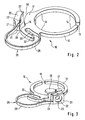
- the retaining ring 12 is part of a spiral clamp 16, which in the figures 2 and 3 is shown in more detail.
- This inner clamping surface 18 extends to a radius to Rotary axis 2 of the balance shaft, the radius of the outer end 19 of the Coil spring 13 corresponds.
- the inner jaw 17 is radially opposite opposite each other an outer clamping jaw 20, the one of the inner clamping surface 18 opposite outer clamping surface 21 has.
- This outer clamping surface 21 extends to a radius to the axis of rotation 2 of the balance shaft, the to the thickness of the coil spring 3 is greater than the radius of the inner Clamping surface 18.
- a continuous Recess 22 formed in the outer clamping surface 21 approximately opens centrally and in their radially outer mouth area as a recess 23 extended to accommodate a countersunk head of a countersunk screw 24 is that forms a clamping screw.
- the countersunk screw 24 can be inserted and with its threaded shaft in a recess 22 approximately coaxially formed in the inner jaw 17 and centered in the inner Clamping surface 18 opening threaded hole screwed.
- the spring arm is a flat spring arm with approximately rectangular cross section, whose long cross-sectional sides 26 are directed parallel to the axis of rotation 2 are.
- the outer end of the coil spring 3 is opposite to the spring arm 25 Side fro between the inner clamping surface 18 and the outer Clamping surface 21 is inserted and projects into the spring arm of the 25th enclosed area inside.
- the coil spring 3 is on one level guided under the countersunk screw 24 along.
- a support surface 27 is formed, which extends with a radius to the axis of rotation 2 curved, which corresponds to the radius of the inner clamping surface 18th equivalent.
- This inner clamping surface 18 extends axially over both the area of the plane above the tapped hole as well as above the area the level under the tapped hole.
- the support surface 27 is located directly in the upper level of the inner clamping surface 18 flat.
- Stop 30 is arranged, which protrudes toward the outer clamping jaw 20 and on which the outer end 19 of the coil spring 3 rests and axially to Rotary axis 2 is supported.
- This stop 30 projects so far in the direction of the outer clamping jaw 20, that the stopper 30 during clamping of the clamping jaws 17 and 20 on the bottom 31 of the outer jaw 20 comes to rest and also this is supported axially to the axis of rotation 2. This can be done at a Screw in and unscrew the countersunk screw 24 on the outer jaw 20 acting torque does not twist the jaw 20 and the spring arm 25 lead.
- the spiral clamp 16 as one-piece component formed from the retaining ring 12, the inner Clamping jaw 17, the spring arm 25, the outer jaw 20 and the slot 32 having extension, wherein this Component of the stop 30 is arranged.
- the locking screw 33 is loosened and the Retaining ring 12 and with him the entire spiral clamp 16 overcoming the frictional engagement is rotated on the cylinder component 5 for coarse adjustment, the fine adjustment by the fine adjustment screw by common Twisting cylinder member 5 and spiral clamp 16 under overcoming the frictional engagement between the cylinder component 5 and balance cock 4 he follows. Thereafter, the spiral clamp 16 by tightening the locking screw fixed again.
Landscapes
- Physics & Mathematics (AREA)
- General Physics & Mathematics (AREA)
- Clamps And Clips (AREA)
- Springs (AREA)
- Apparatuses For Generation Of Mechanical Vibrations (AREA)
Abstract
Description
- Figur 1
- eine perspektivische Ansicht eines Schwingsystems
- Figur 2
- eine perspektivische Ansicht eine Spiralklemme des Schwingsystems nach Figur 1
- Figur 3
- eine verkleinerte weitere perspektivische Ansicht der Spiralklemme nach Figur 2.
- 1
- Unruh
- 2
- Drehachse
- 3
- Spiralfeder
- 4
- Unruhkloben
- 5
- Zylinderbauteil
- 6
- Rückerzeiger
- 7
- freies Ende
- 8
- Schwanenhalsfeder
- 9
- Stirnfläche
- 10
- Feineinstellschraube
- 11
- Block
- 12
- Haltering
- 13
- Öffnung
- 14
- Bereich der Öffnung
- 15
- Bereich
- 16
- Spiralklemme
- 17
- innere Spannfläche
- 18
- innere Spannfläche
- 19
- äußeres Ende
- 20
- äußere Spannbacke
- 21
- äußere Spannfläche
- 22
- Ausnehmung
- 23
- Vertiefung
- 24
- Senkkopfschraube
- 25
- Federarm
- 26
- lange Querschnittsseite
- 27
- Abstützfläche
- 28
- Einführbereich
- 29
- Ausführbereich
- 30
- Anschlag
- 31
- Unterseite
- 32
- Langloch
- 33
- Feststellschraube
Claims (29)
- Schwingsystem für eine mechanische Uhr, mit einer ringförmigen Unruh, die koaxial auf einer drehbar gelagerten Unruhwelle fest angeordnet ist, mit einer die Unruhwelle umschließenden Spiralfeder, die mit ihrem inneren Ende an der Unruhwelle und deren äußeres Ende an einer Befestigungsvorrichtung befestigt ist, dadurch gekennzeichnet, daß die Befestigungsvorrichtung eine Spiralklemme (16) mit einer zur Drehachse (2) der Unruhwelle radial inneren Spannbacke (17) und einer radial äußeren Spannbacke (20) aufweist, wobei das äußere Ende (19) der Spiralfeder (3) zwischen einer Spannfläche (18) der inneren Spannbacke (17) und einer Spannfläche (21) der äußeren Spannbacke (20) fest einklemmbar ist.
- Schwingsystem nach Anspruch 1, dadurch gekennzeichnet, daß die radial innere Spannbacke (17) fest anordenbar und die radial äußere Spannbacke (20) etwa radial bewegbar ist.
- Schwingsystem nach einem der vorhergehenden Ansprüche, dadurch gekennzeichnet, daß die innere Spannbacke (17) und die äußere Spannbacke (20) mittels einer Spannschraube gegeneinander verspannbar sind.
- Schwingsystem nach Anspruch 3, dadurch gekennzeichnet, daß die Spannschraube durch eine etwa radial zur Unruhwelle gerichtete Ausnehmung (22) der äußeren Spannbacke (20) hindurchgeführt, mit ihrem Schraubenkopf an der äußeren Spannbacke (20) abgestützt und mit ihrem Gewindeschaft in eine zur Ausnehmung (22) etwa koaxialen Gewindebohrung in der inneren Spannbacke (17) einschraubbar ist.
- Schwingsystem nach Anspruch 4, dadurch gekennzeichnet, daß die Spannschraube eine Senkkopfschraube (24) ist, deren Senkkopf in eine entsprechende Vertiefung (23) in dem der inneren Spannbacke (17) abgewandten Mündungsbereich der Ausnehmung (22) einsetzbar ist.
- Schwingsystem nach einem der vorhergehenden Ansprüche, dadurch gekennzeichnet, daß die Spannflächen (18, 21) der inneren und/oder der äußeren Spannbacke (17, 20) zur Unruhwelle etwa konzentrisch gewölbt sind.
- Schwingsystem nach Anspruch 6, dadurch gekennzeichnet, daß sich die Spannfläche (21) der äußeren Spannbacke (20) mit einem Radius zur Drehachse (2) der Unruhwelle konzentrisch gewölbt erstreckt, der um etwa die Dicke der Spiralfeder (3) größer ist als der Radius, um den sich die Spannfläche (18) der inneren Spannbacke (17) zur Drehachse (2) der Unruhwelle konzentrisch gewölbt erstreckt.
- Schwingsystem nach einem der vorhergehenden Ansprüche, dadurch gekennzeichnet, daß sich die Spannfläche (18) der inneren Spannbacke (17) auf einem Radius zur Drehachse (2) der Unruhwelle erstreckt, der etwa dem inneren Radius des äußeren Endes (19) der Spiralfeder (3) entspricht.
- Schwingsystem nach einem der Ansprüche 3 bis 8, dadurch gekennzeichnet, daß sich das äußere Ende (19) der Spiralfeder (3) axial zur Drehachse (2) der Unruhwelle neben der Spannschraube zwischen den Spannflächen (18, 21) der inneren und äußeren Spannbacke (17, 20) erstreckt.
- Schwingsystem nach Anspruch 9, dadurch gekennzeichnet, daß axial zur Drehachse (2) der Unruhwelle auf der dem Ende (19) der Spiralfeder (3) gegenüberliegenden Seite der Spannschraube die äußere Spannbacke (20) eine Abstützfläche (27) besitzt, die sich mit einem Radius zur Drehachse (2) der Unruhwelle gewölbt erstreckt, der etwa dem Radius der Spannfläche (18) der inneren Spannbacke (17) entspricht.
- Schwingsystem nach einem der vorhergehenden Ansprüche, dadurch gekennzeichnet, daß die äußere Spannbacke (20) über einen Federarm (25) mit der inneren Spannbacke (17) verbunden ist.
- Schwingsystem nach Anspruch 11, dadurch gekennzeichnet, daß der Federarm (25) ein Flachfederarm mit etwa recheckigem Querschnitt ist, dessen lange Querschnittsseiten (26) parallel zur Drehachse (2) der Unruhwelle gerichtet sind.
- Schwingsystem nach einem der Ansprüche 11 und 12, dadurch gekennzeichnet, daß sich der Federarm (25) etwa schwanenhalsartig von der inneren Spannbacke (17) zur äußeren Spannbacke (20) erstreckt.
- Schwingsystem nach einem der Ansprüche 2 bis 13, dadurch gekennzeichnet, daß die innere Spannbacke (17) an einem Haltering (12) befestigt ist, der um einen bestimmten Winkelbereich verdrehbar einstellbar ein zur Drehachse (2) der Unruhwelle koaxiales Zylinderbauteil (5) mit Kraft- und/oder Form- und/oder Reibschluß umgreift.
- Schwingsystem nach Anspruch 14, dadurch gekennzeichnet, daß der Haltering (12) ein offener Haltering (12) ist, dessen Öffnung (13) etwa diametral der inneren Spannbacke (17) gegenüber liegt und der mit einer radial nach innen gerichteten Federkraft das Zylinderbauteil (5) umgreift.
- Schwingsystem nach Anspruch 15, dadurch gekennzeichnet, daß der innere Krümmungsradius des Halterings (12) im Bereich der inneren Spannbacke (17) um ein geringes Maß größer ist als im Bereich der Öffnung (13) des Halterings (12).
- Schwingsystem nach einem der vorhergehenden Ansprüche, dadurch gekennzeichnet, daß das Zylinderbauteil (5) um die Drehachse (2) der Unruhwelle drehbar einstellbar ist und einen radial hervorstehenden Rückerzeiger (6) aufweist.
- Schwingsystem nach Anspruch 17, dadurch gekennzeichnet, daß der Rückerzeiger (6) von einem Einstellmechanismus um die Drehachse (2) der Unruhwelle verschwenkbar einstellbar ist.
- Schwingsystem nach Anspruch 18, dadurch gekennzeichnet, daß der Einstellmechanismus eine Stellschraube ist, die den Rückerzeiger (6) in Schwenkrichtung entgegen der Kraft einer Feder beaufschlagt.
- Schwingsystem nach Anspruch 19, dadurch gekennzeichnet, daß die Stellschraube eine Feineinstellschraube (10) ist.
- Schwingsystem nach Anspruch 19, dadurch gekennzeichnet, daß die Feder eine mit ihrem einen Ende fest angeordnete Schwanenhalsfeder (8) ist, die unter Vorspannung an dem Rückerzeiger (6) in Anlage ist.
- Schwingsystem nach einem der vorhergehenden Ansprüche, dadurch gekennzeichnet, daß im Bereich des dem äußeren Ende (19) der Spiralfeder (3) näheren Endes der Spannfläche (18) der inneren Spannbacke (17) ein Anschlag (30) angeordnet ist, der zur äußeren Spannbacke (20) hin hervorsteht und auf dem der Bereich des äußeren Endes (19) der Spiralfeder (3) axial zur Drehachse (2) der Unruhwelle abstützbar ist.
- Schwingsystem nach Anspruch 22, dadurch gekennzeichnet, daß an dem Anschlag (30) die äußere Spannbacke (20) axial zur Drehachse (2) der Unruhwelle abstützbar ist.
- Schwingsystem nach einem der Ansprüche 15 bis 23, dadurch gekennzeichnet, daß der Haltering (12) innerhalb des bestimmten Winkelbereichs in eine bestimmte Position verdrehbar einstellbar und in dieser Position feststellbar ist.
- Schwingsystem nach Anspruch 24, dadurch gekennzeichnet, daß der Haltering (12) ein sich konzentrisch zur Drehachse (2) der Unruhwelle erstreckendes Langloch (32) besitzt, durch das eine Feststellschraube (33) in eine im Bereich des Langlochs (32) in einem Unruhkloben (4) ausgebildete Gewindebohrung einschraubbar und der Haltering (12) gegen den Unruhkloben (4) verspannbar ist.
- Schwingsystem nach Anspruch 25, dadurch gekennzeichnet, daß das Langloch (32) nahe oder im Bereich der inneren Spannbacke (17) angeordnet ist.
- Schwingsystem nach einem der Ansprüche 25 und 26, dadurch gekennzeichnet, daß das Langloch (32) an seinem einen Ende offen ist.
- Schwingsystem nach einem der Ansprüche 11 bis 27, dadurch gekennzeichnet, daß die innere Spannbacke (17), die äußere Spannbacke (20) und der Federarm (25) einteilig ausgebildet sind.
- Schwingsystem nach einem der Ansprüche 11 bis 28, dadurch gekennzeichnet, daß die innere Spannbacke (17) und der Haltering (12) einteilig ausgebildet sind.
Applications Claiming Priority (2)
| Application Number | Priority Date | Filing Date | Title |
|---|---|---|---|
| DE10345918A DE10345918A1 (de) | 2003-10-02 | 2003-10-02 | Schwingsystem |
| DE10345918 | 2003-10-02 |
Publications (3)
| Publication Number | Publication Date |
|---|---|
| EP1521140A2 true EP1521140A2 (de) | 2005-04-06 |
| EP1521140A3 EP1521140A3 (de) | 2007-10-03 |
| EP1521140B1 EP1521140B1 (de) | 2009-09-30 |
Family
ID=34306231
Family Applications (1)
| Application Number | Title | Priority Date | Filing Date |
|---|---|---|---|
| EP04019537A Active EP1521140B1 (de) | 2003-10-02 | 2004-08-18 | Schwingsystem |
Country Status (3)
| Country | Link |
|---|---|
| US (1) | US7237945B2 (de) |
| EP (1) | EP1521140B1 (de) |
| DE (2) | DE10345918A1 (de) |
Families Citing this family (12)
| Publication number | Priority date | Publication date | Assignee | Title |
|---|---|---|---|---|
| EP2437126B1 (de) * | 2010-10-04 | 2019-03-27 | Rolex Sa | Regulierorgan mit Spiralunruh |
| EP2570871B1 (de) * | 2011-09-14 | 2014-03-19 | Montres Breguet SA | Spirale mit zwei Spiralfedern |
| USD700535S1 (en) * | 2011-12-28 | 2014-03-04 | Nivarox-Far S.A. | Balance wheel with control knobs |
| EP2781970B1 (de) * | 2013-03-19 | 2016-03-16 | Nivarox-FAR S.A. | Spiralfederregulierungsmechanismus einer Uhr |
| CH707815B1 (fr) * | 2013-03-19 | 2017-05-31 | Nivarox Far Sa | Sous-ensemble de mécanisme d'échappement d'horlogerie comportant un ressort-spiral. |
| CH707811A2 (fr) * | 2013-03-19 | 2014-09-30 | Nivarox Sa | Composant monobloc indémontable d'horlogerie. |
| EP2876504B1 (de) * | 2013-11-20 | 2017-07-26 | ETA SA Manufacture Horlogère Suisse | Schraubenloser Spiralklötzchen-Träger für Uhr |
| EP2887154B1 (de) * | 2013-12-20 | 2016-07-20 | Blancpain SA. | Befestigungsmechanismus eines Spiralklötzchen an eine Unruhbrücke, und Reguliervorrichtung mit Unruh-Spiralfeder, die einen solchen Mechanismus umfasst |
| EP2980658B1 (de) * | 2014-08-01 | 2017-07-19 | Agenhor SA | Vorrichtung zum Zusammenbau und Regulieren einer Spirale |
| JP6710041B2 (ja) * | 2014-11-27 | 2020-06-17 | ロレックス・ソシエテ・アノニムRolex Sa | ヒゲゼンマイ固定システム |
| EP3032353B1 (de) * | 2014-12-11 | 2019-08-07 | ETA SA Manufacture Horlogère Suisse | Ausbaubarer Spiralklötzchenträger |
| EP3179314B1 (de) * | 2015-12-11 | 2018-11-14 | ETA SA Manufacture Horlogère Suisse | Spiralklötzchenträger mit vereinfachter montage |
Citations (4)
| Publication number | Priority date | Publication date | Assignee | Title |
|---|---|---|---|---|
| US221180A (en) | 1879-08-19 | 1879-11-04 | Improvement in hair-spring studs | |
| US1037741A (en) | 1911-04-19 | 1912-09-03 | Hamilton Watch Co | Balance-cock. |
| FR958511A (de) | 1950-03-13 | |||
| FR2070901A1 (de) | 1969-12-17 | 1971-09-17 | Portescap |
Family Cites Families (11)
| Publication number | Priority date | Publication date | Assignee | Title |
|---|---|---|---|---|
| CH24677A (fr) | 1902-02-22 | 1903-01-31 | Charles Rosat | Dispositif régulateur pour raquette montée sur un porte-spiral pouvaut tourner autour de l'axe du balancier |
| US2584786A (en) * | 1948-05-04 | 1952-02-05 | Ingraham E Co | Method for providing timepieces with spiral-helix hairsprings |
| US2619933A (en) * | 1950-07-05 | 1952-12-02 | Bendix Aviat Corp | Adjustable torque and deflection control mechanism for indicating instruments |
| US2698509A (en) * | 1951-11-23 | 1955-01-04 | Rhodes Inc M H | Balance spring for clockwork mechanisms |
| US2896399A (en) * | 1956-07-18 | 1959-07-28 | Manuf Des Montres Doxa S A | Regulator system for a timepiece |
| US3241307A (en) * | 1961-11-17 | 1966-03-22 | Hubert E Dickerman | Timepiece regulating means |
| DE1257689B (de) | 1965-10-16 | 1967-12-28 | Kienzle Uhrenfabriken Gmbh | Vorrichtung zum Festlegen des aeusseren Spiralfederendes am Gestell von Unruh-Uhren |
| DE4435704C2 (de) * | 1994-10-06 | 1997-04-24 | Lange Uhren Gmbh | Schwingsystem |
| CH692532A5 (fr) * | 1997-10-21 | 2002-07-15 | Ebauchesfabrik Eta Ag | Procédé de fabrication d'un spiral de balancier pour mouvement d'horlogerie. |
| EP1199615A4 (de) * | 1999-07-29 | 2004-11-10 | Seiko Instr Inc | Mechanische uhr mit stiftförmigem stellmechanismus |
| WO2001035171A1 (fr) * | 1999-11-11 | 2001-05-17 | Seiko Instruments Inc. | Piece d'horlogerie mecanique dotee d'un mecanisme de commande de l'angle de rotation du balancier annulaire regle |
-
2003
- 2003-10-02 DE DE10345918A patent/DE10345918A1/de not_active Ceased
-
2004
- 2004-08-18 DE DE502004010149T patent/DE502004010149D1/de active Active
- 2004-08-18 EP EP04019537A patent/EP1521140B1/de active Active
- 2004-09-21 US US10/945,595 patent/US7237945B2/en active Active
Patent Citations (4)
| Publication number | Priority date | Publication date | Assignee | Title |
|---|---|---|---|---|
| FR958511A (de) | 1950-03-13 | |||
| US221180A (en) | 1879-08-19 | 1879-11-04 | Improvement in hair-spring studs | |
| US1037741A (en) | 1911-04-19 | 1912-09-03 | Hamilton Watch Co | Balance-cock. |
| FR2070901A1 (de) | 1969-12-17 | 1971-09-17 | Portescap |
Also Published As
| Publication number | Publication date |
|---|---|
| DE10345918A1 (de) | 2005-05-12 |
| DE502004010149D1 (de) | 2009-11-12 |
| EP1521140B1 (de) | 2009-09-30 |
| US7237945B2 (en) | 2007-07-03 |
| US20050073912A1 (en) | 2005-04-07 |
| EP1521140A3 (de) | 2007-10-03 |
Similar Documents
| Publication | Publication Date | Title |
|---|---|---|
| EP0614649B1 (de) | Knochenschraube | |
| DE10000728C2 (de) | Klammervorrichtung für Stangen | |
| EP0616512B1 (de) | Verankerungselement | |
| DE19507141B4 (de) | Arretierwerkzeug | |
| DE19720782B4 (de) | Vorrichtung zur Verbindung eines Längsträgers mit einer Pedikelschraube | |
| EP1521140B1 (de) | Schwingsystem | |
| EP1514522B1 (de) | Knochenschraube | |
| EP0782898B1 (de) | Verfahren zum Befestigen eines Spannaufsatzes auf einem Werkstück und Vorrichtung zu seiner Durchführung | |
| EP2766581B1 (de) | Nockenwelle sowie funktionselemente für eine nockenwelle | |
| EP0576652A1 (de) | Implantat zur ausrichtung und fixierung zweier knochen oder knochenteile zueinander, insbesondere spondylodese-implantat. | |
| EP0732081A1 (de) | Verankerungselement | |
| DE2040020A1 (de) | Bohreinheit,insbesondere zur Durchfuehrung von Feinbohrarbeiten | |
| WO2002024387A1 (de) | Zerspanungswerkzeug | |
| EP2097199B1 (de) | Systempendelvorrichtung und verfahren | |
| DE3923131A1 (de) | Befestigungselement, insbesondere fuer eine kugel-gewindespindel | |
| EP1262266B1 (de) | Spannvorrichtung | |
| EP1593461A1 (de) | Innenspanner zum Spannen einer Schraubenfeder | |
| DE4435704C2 (de) | Schwingsystem | |
| DE102004050625A1 (de) | Einstell- und Befestigungseinrichtung | |
| DE3042050A1 (de) | Vorrichtung zum einstellen eines schneidkoerpers gegenueber einem traeger | |
| EP1484653A2 (de) | Feinreguliervorrichtung | |
| DE3219011C2 (de) | ||
| EP2949847A1 (de) | Verstellbarer steuerhebel | |
| EP4091769B1 (de) | Schraubstock | |
| DE102021123121A1 (de) | Werkstückanschlag und Spannvorrichtung mit Werkstückanschlag |
Legal Events
| Date | Code | Title | Description |
|---|---|---|---|
| PUAI | Public reference made under article 153(3) epc to a published international application that has entered the european phase |
Free format text: ORIGINAL CODE: 0009012 |
|
| AK | Designated contracting states |
Kind code of ref document: A2 Designated state(s): AT BE BG CH CY CZ DE DK EE ES FI FR GB GR HU IE IT LI LU MC NL PL PT RO SE SI SK TR |
|
| AX | Request for extension of the european patent |
Extension state: AL HR LT LV MK |
|
| PUAL | Search report despatched |
Free format text: ORIGINAL CODE: 0009013 |
|
| AK | Designated contracting states |
Kind code of ref document: A3 Designated state(s): AT BE BG CH CY CZ DE DK EE ES FI FR GB GR HU IE IT LI LU MC NL PL PT RO SE SI SK TR |
|
| AX | Request for extension of the european patent |
Extension state: AL HR LT LV MK |
|
| 17P | Request for examination filed |
Effective date: 20080207 |
|
| AKX | Designation fees paid |
Designated state(s): CH DE IT LI |
|
| 17Q | First examination report despatched |
Effective date: 20080926 |
|
| GRAP | Despatch of communication of intention to grant a patent |
Free format text: ORIGINAL CODE: EPIDOSNIGR1 |
|
| GRAS | Grant fee paid |
Free format text: ORIGINAL CODE: EPIDOSNIGR3 |
|
| GRAA | (expected) grant |
Free format text: ORIGINAL CODE: 0009210 |
|
| AK | Designated contracting states |
Kind code of ref document: B1 Designated state(s): CH DE IT LI |
|
| REG | Reference to a national code |
Ref country code: CH Ref legal event code: EP |
|
| REF | Corresponds to: |
Ref document number: 502004010149 Country of ref document: DE Date of ref document: 20091112 Kind code of ref document: P |
|
| PLBE | No opposition filed within time limit |
Free format text: ORIGINAL CODE: 0009261 |
|
| STAA | Information on the status of an ep patent application or granted ep patent |
Free format text: STATUS: NO OPPOSITION FILED WITHIN TIME LIMIT |
|
| 26N | No opposition filed |
Effective date: 20100701 |
|
| PG25 | Lapsed in a contracting state [announced via postgrant information from national office to epo] |
Ref country code: IT Free format text: LAPSE BECAUSE OF FAILURE TO SUBMIT A TRANSLATION OF THE DESCRIPTION OR TO PAY THE FEE WITHIN THE PRESCRIBED TIME-LIMIT Effective date: 20090930 |
|
| PGFP | Annual fee paid to national office [announced via postgrant information from national office to epo] |
Ref country code: CH Payment date: 20230913 Year of fee payment: 20 |
|
| PGFP | Annual fee paid to national office [announced via postgrant information from national office to epo] |
Ref country code: DE Payment date: 20230920 Year of fee payment: 20 |