EP1521005B1 - Kupplungs- und/oder Bremseinheit - Google Patents
Kupplungs- und/oder Bremseinheit Download PDFInfo
- Publication number
- EP1521005B1 EP1521005B1 EP04104616A EP04104616A EP1521005B1 EP 1521005 B1 EP1521005 B1 EP 1521005B1 EP 04104616 A EP04104616 A EP 04104616A EP 04104616 A EP04104616 A EP 04104616A EP 1521005 B1 EP1521005 B1 EP 1521005B1
- Authority
- EP
- European Patent Office
- Prior art keywords
- lamella
- clutch
- brake unit
- component
- unit according
- Prior art date
- Legal status (The legal status is an assumption and is not a legal conclusion. Google has not performed a legal analysis and makes no representation as to the accuracy of the status listed.)
- Expired - Lifetime
Links
- 241000446313 Lamella Species 0.000 claims description 53
- 238000013461 design Methods 0.000 claims description 7
- 230000013011 mating Effects 0.000 claims 1
- 230000008878 coupling Effects 0.000 description 7
- 238000010168 coupling process Methods 0.000 description 7
- 238000005859 coupling reaction Methods 0.000 description 7
- 230000005540 biological transmission Effects 0.000 description 6
- 238000012549 training Methods 0.000 description 4
- 238000011161 development Methods 0.000 description 2
- 230000018109 developmental process Effects 0.000 description 2
- 239000010720 hydraulic oil Substances 0.000 description 2
- 239000007788 liquid Substances 0.000 description 2
- 238000012986 modification Methods 0.000 description 2
- 230000004048 modification Effects 0.000 description 2
- 239000003921 oil Substances 0.000 description 2
- 238000010276 construction Methods 0.000 description 1
- 230000001419 dependent effect Effects 0.000 description 1
- 239000012530 fluid Substances 0.000 description 1
- 238000003475 lamination Methods 0.000 description 1
- 238000004519 manufacturing process Methods 0.000 description 1
- 238000012545 processing Methods 0.000 description 1
Images

Classifications
-
- F—MECHANICAL ENGINEERING; LIGHTING; HEATING; WEAPONS; BLASTING
- F16—ENGINEERING ELEMENTS AND UNITS; GENERAL MEASURES FOR PRODUCING AND MAINTAINING EFFECTIVE FUNCTIONING OF MACHINES OR INSTALLATIONS; THERMAL INSULATION IN GENERAL
- F16D—COUPLINGS FOR TRANSMITTING ROTATION; CLUTCHES; BRAKES
- F16D55/00—Brakes with substantially-radial braking surfaces pressed together in axial direction, e.g. disc brakes
- F16D55/02—Brakes with substantially-radial braking surfaces pressed together in axial direction, e.g. disc brakes with axially-movable discs or pads pressed against axially-located rotating members
- F16D55/22—Brakes with substantially-radial braking surfaces pressed together in axial direction, e.g. disc brakes with axially-movable discs or pads pressed against axially-located rotating members by clamping an axially-located rotating disc between movable braking members, e.g. movable brake discs or brake pads
- F16D55/228—Brakes with substantially-radial braking surfaces pressed together in axial direction, e.g. disc brakes with axially-movable discs or pads pressed against axially-located rotating members by clamping an axially-located rotating disc between movable braking members, e.g. movable brake discs or brake pads with a separate actuating member for each side
-
- F—MECHANICAL ENGINEERING; LIGHTING; HEATING; WEAPONS; BLASTING
- F16—ENGINEERING ELEMENTS AND UNITS; GENERAL MEASURES FOR PRODUCING AND MAINTAINING EFFECTIVE FUNCTIONING OF MACHINES OR INSTALLATIONS; THERMAL INSULATION IN GENERAL
- F16D—COUPLINGS FOR TRANSMITTING ROTATION; CLUTCHES; BRAKES
- F16D25/00—Fluid-actuated clutches
- F16D25/06—Fluid-actuated clutches in which the fluid actuates a piston incorporated in, i.e. rotating with the clutch
- F16D25/062—Fluid-actuated clutches in which the fluid actuates a piston incorporated in, i.e. rotating with the clutch the clutch having friction surfaces
- F16D25/063—Fluid-actuated clutches in which the fluid actuates a piston incorporated in, i.e. rotating with the clutch the clutch having friction surfaces with clutch members exclusively moving axially
- F16D25/0635—Fluid-actuated clutches in which the fluid actuates a piston incorporated in, i.e. rotating with the clutch the clutch having friction surfaces with clutch members exclusively moving axially with flat friction surfaces, e.g. discs
- F16D25/0638—Fluid-actuated clutches in which the fluid actuates a piston incorporated in, i.e. rotating with the clutch the clutch having friction surfaces with clutch members exclusively moving axially with flat friction surfaces, e.g. discs with more than two discs, e.g. multiple lamellae
-
- F—MECHANICAL ENGINEERING; LIGHTING; HEATING; WEAPONS; BLASTING
- F16—ENGINEERING ELEMENTS AND UNITS; GENERAL MEASURES FOR PRODUCING AND MAINTAINING EFFECTIVE FUNCTIONING OF MACHINES OR INSTALLATIONS; THERMAL INSULATION IN GENERAL
- F16D—COUPLINGS FOR TRANSMITTING ROTATION; CLUTCHES; BRAKES
- F16D25/00—Fluid-actuated clutches
- F16D25/10—Clutch systems with a plurality of fluid-actuated clutches
-
- F—MECHANICAL ENGINEERING; LIGHTING; HEATING; WEAPONS; BLASTING
- F16—ENGINEERING ELEMENTS AND UNITS; GENERAL MEASURES FOR PRODUCING AND MAINTAINING EFFECTIVE FUNCTIONING OF MACHINES OR INSTALLATIONS; THERMAL INSULATION IN GENERAL
- F16D—COUPLINGS FOR TRANSMITTING ROTATION; CLUTCHES; BRAKES
- F16D27/00—Magnetically- or electrically- actuated clutches; Control or electric circuits therefor
- F16D27/12—Clutch systems with a plurality of electro-magnetically-actuated clutches
-
- F—MECHANICAL ENGINEERING; LIGHTING; HEATING; WEAPONS; BLASTING
- F16—ENGINEERING ELEMENTS AND UNITS; GENERAL MEASURES FOR PRODUCING AND MAINTAINING EFFECTIVE FUNCTIONING OF MACHINES OR INSTALLATIONS; THERMAL INSULATION IN GENERAL
- F16D—COUPLINGS FOR TRANSMITTING ROTATION; CLUTCHES; BRAKES
- F16D67/00—Combinations of couplings and brakes; Combinations of clutches and brakes
- F16D67/02—Clutch-brake combinations
- F16D67/04—Clutch-brake combinations fluid actuated
-
- F—MECHANICAL ENGINEERING; LIGHTING; HEATING; WEAPONS; BLASTING
- F16—ENGINEERING ELEMENTS AND UNITS; GENERAL MEASURES FOR PRODUCING AND MAINTAINING EFFECTIVE FUNCTIONING OF MACHINES OR INSTALLATIONS; THERMAL INSULATION IN GENERAL
- F16D—COUPLINGS FOR TRANSMITTING ROTATION; CLUTCHES; BRAKES
- F16D2121/00—Type of actuator operation force
- F16D2121/02—Fluid pressure
Definitions
- the invention relates to a clutch and / or brake unit with at least three relatively rotatable components, with each of which at least one lamella is rotatably connected, wherein the lamellae can be selectively brought into frictional engagement with each other.
- Conventional clutch and / or brake units are equipped with a plate carrier on which there is at least one lamella for an external clutch and / or brake unit and at least one further lamella for an internal clutch and / or brake unit.
- the inner and outer slats are usually connected by means of spline teeth with a plate carrier.
- two different disks are required for two clutch and / or brake units, which are non-rotatably connected to a component, the disk carrier.
- the object underlying the invention is seen to provide a coupling and / or brake unit of the type mentioned, which has a simplified structure and can be produced easily and inexpensively.
- the coupling and / or brake unit according to the invention contains at least three components rotatable relative to one another, with which in each case at least one lamella is non-rotatably connected.
- the slats can optionally be brought into frictional engagement with each other.
- the invention is characterized by a so-called single-disc design. This is characterized in that with the first component at least one first fin is rotatably connected, which at least one radially outer friction lining with at least one second rotatably connected to the second component connected slat can be brought into frictional engagement, and which can be brought into frictional engagement with at least one radially inner friction lining with at least a third non-rotatably connected to the third component blade.
- the clutch and / or brake unit according to the invention has a simple structure, since instead of a usual inner and outer blade now only a single blade is required, both an inner clutch and / or brake unit and an outer clutch and / or Brake unit is assigned.
- This training leads to a simplified and inexpensive to produce construction. It is advantageous to tie the at least one lamella flat and disc-shaped.
- the invention is not only suitable for clutch and / or brake unit with a single first blade, which cooperates with second and third blades. Rather, it is also applicable to multi-plate clutches and brakes, wherein at least one component is connected to a plate pack, which comprises the respective at least one blade.
- the at least one first lamella is element of a first lamella packet and / or the at least one second or third lamella is element of a second or third lamella packet.
- the friction engagement (clutch or brake) between the at least one first plate or the first plate set and the at least one second plate or the second plate set and the frictional engagement (clutch or brake) between the at least one first plate or the first plate pack and the at least one third lamination or the third lamella packet is preferably carried out by mechanical actuation (eg by lever, ball-ramp principle, wedge, etc.) hydraulic actuation (eg by means of a piston), by pneumatic actuation (eg by means of a piston) or by electrical actuation (eg using an electric motor).
- mechanical actuation eg by lever, ball-ramp principle, wedge, etc.
- hydraulic actuation eg by means of a piston
- pneumatic actuation eg by means of a piston
- electrical actuation eg using an electric motor
- the slats or the disk packs are expediently clamped with the aid of a disk clutch, so that a torque is transmitted.
- the two friction interventions can be switched independently of each other. Elements of at least one of the two friction engagements should be axially displaceable in order to avoid jamming of the slats with simultaneous actuation of both friction engagements, and also to compensate for a different wear of the friction linings applied to the slats.
- first driving component mounted on a rotatable shaft the first component can be connected to the second component or to the third component or both to the second component and to the third component.
- second driving component mounted on a rotatable shaft the second component can be connected to the first component or both to the first component and to the third component.
- third driving component mounted on a rotatable shaft the third component can be connected to the first component or both to the first component and to the second component.
- the first component is a plate carrier with at least one, preferably with at least two axially projecting webs (drivers), which engage in corresponding recesses of the at least one first plate.
- the first component (plate carrier) with the webs on or be executed in several parts.
- the webs of the first component can be designed in different ways. So it is advantageous for manufacturing reasons, the webs form substantially cylindrical, wherein the webs engage in circular openings of the at least one first blade.
- other positive connections between plate carrier and plate are also conceivable (eg circular segments as driver).
- the webs of the first component can pass through these holes or punched holes, so that the lamella is positively connected to the first component.
- the webs of the first component can pass through these holes or punched holes, so that the lamella is positively connected to the first component.
- For plate carrier and plate only one shaft-hub connection is necessary.
- the at least one radially outer friction lining is preferably located radially outside the webs (of the diameter region on which the webs are arranged) and the at least one radially inner friction lining lies radially inside the webs.
- At least one lamella is axially displaceable with respect to the component carrying it.
- the at least one first, second and / or third lamella or the first, second and / or third lamella packet is axially displaceable relative to the associated first, second and / or third component.
- the first lamella is axially displaceable on the webs of the first component (disk carrier).
- the at least one first blade without friction lining and the at least one second and third counter-blade are formed with friction linings.
- areas with different friction linings are provided to allow different friction factors.
- grooves may also run in the slat surfaces, which are designed differently in different surface areas.
- regions of different friction linings or groove design are arranged concentrically to one another.
- At least one lamella cooperates with a caliper, by means of which this lamella and with it the associated component decelerate and can be stopped relative to a transmission housing.
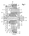
- the coupling unit shown contains as a second component a shaft 10, on whose one end serving as a third component clutch bell 12 and at the other end serving as a first component disc carrier 14 are rotatably mounted.
- the bearing 16 between the second and the third component 10, 12 and the bearing 18 between the second and the first component may be formed as a conventional sliding, needle or roller bearings, which allow a relative rotation of the three components 10, 12, 14 against each other.
- the plate carrier 14 includes a connecting shaft 20 which carries a flange-like part 22. To the flange-like part 22 are three evenly distributed on the circumference, axially extending into the clutch bell 12, serving as a driver webs 24 are formed, two of which are shown.
- the webs 24 are formed according to the illustrated embodiment as a cylindrical bolt, but in principle may have other cross-sectional shapes.
- the webs 24 extend through circular bores 26, which are formed in three radially extending disc-shaped plates 28, 30, 32, so that a positive connection between the plate carrier 14 and the three blades 28, 30, 32 results, which the transmission of Torque allows.
- a first lamella 28 has a larger outer diameter than the two other lamellae 30, 32 arranged on both sides of the first lamella 28.
- the three lamellae 28, 30, 32 can be displaced axially on the webs 24.
- the radial region at the level of the webs 24 on which the three circular bores 22 lie divides the first blade 28 into an annular outer contact region 34 and an annular inner contact region 36.
- the clutch bell 12 is cup-shaped and includes at one axial end a hub portion 38 and at the other axial end a ring portion 40. Within the ring portion 40, two outer counter-blades 42 are rotatably and axially displaceably arranged. A locking ring 43 holds the outer counter blades 42 in the clutch bell 12. The outer counter blades 42 have annular contact areas, which corresponds to the mutual outer contact portions 34 of the blade 28. The blade 28 and the outer counter-blades 42 are part of an outer clutch, which further includes an axially movable clutch piston 44.
- liquid for example hydraulic oil
- the clutch piston 44 moves in the axial direction and presses the first disk 28 and the two outer counter disks 42 together, whereby a frictional connection is formed and torques between the clutch bell 12 and the plate carrier 14 are transferable.
- the shaft 10 On the shaft 10 are four inner counter-blades 48 rotatably and axially displaceably arranged, which are arranged alternately with the three supported by the plate carrier 14 slats 28, 30, 32 and form a disk set.
- the inner counter blades 48 have annular contact areas which correspond to the inner contact areas 36 of the blades 28, 30, 32.
- the fins 28, 30, 32 and the inner counter blades 48 are part of a radially inner clutch, which further includes an axially movable clutch piston 50.
- one of the components 10, 12, 14 is rotatably connected to the transmission housing.
- the clutch bell 12 may be part of the stationary transmission housing. Then the outer contact regions 34 of the lamella 28 act with the outer counter-lamellae 42 as a brake, by means of which the rotatable lamella carrier 14 can be decelerated. At the same time, the shaft 10 can be braked by closing the inner clutch.
- Fig. 2 is a portion of a second embodiment of a coupling unit according to the invention shown, with the training according to Fig. 1 have many similarities and are substantially similar, so that the same reference numerals have been used for the same components.
- the training according to Fig. 2 is different from the one in Fig. 1 illustrated training essentially in that according to Fig. 2 only a first lamella 28 is rotatably connected to the plate carrier 14, the outer region of which cooperates with two outer counter-louvers 42, which are non-rotatably connected to a clutch bell, not shown, and that the inner region 36 of the first lamella 28 with only two inner counter-lamellae 48, which are rotatably connected to the shaft 10, cooperates.
- the double arrow 56 indicates that an axial movement in both directions is possible.
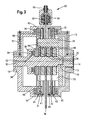
- FIG. 3 was for similar components the same reference numerals as in Fig. 1 used.
- two clutch bells 12, 13 are used.
- a first, left clutch bell 12 is rotatably supported by means of a bearing 16 on the shaft 10
- the second, right clutch bell 13 is by means of a bearing 17 rotatably mounted on the connecting shaft 20 of the disk carrier 14.
- a middle plate 28 With the plate carrier 14, a middle plate 28, a left plate 31 and a right plate 33 are rotatably connected via the driver 24.
- the outer diameter of the middle lamella 28 is greater than the outer diameter of the two clutch bells 12, 13, so that the middle lamella 28 extends between the two clutch bells 12, 13 to the outside.
- a hydraulically actuated brake caliper 60 which contains two brake pistons 62, 64 which are pressed at fluid pressure supply via a hydraulic connection 66 on both sides against outer annular regions of the middle blade 28, so that the middle blade 28 and be braked with her the plate carrier 14.
- the outer contact portions 34 of the left blade 31 cooperate with two non-rotatably arranged in the left clutch bell 12 outer counter-blades 41, which can be brought by a clutch piston 44 in frictional engagement, so that there is a first clutch.
- the outer contact regions 35 of the right-hand lamella 33 cooperate with two outer counter-lamellae 43 which are arranged non-rotatably in the right-hand clutch bell 13 and which can be frictionally engaged by a clutch piston 45 so that a second clutch results.
- the first and the second clutch can be optionally rotatably connected to the plate carrier 14, the left clutch bell 12 and / or the right clutch bell 13.
- the inner contact areas 36 of the middle lamella 28, the left lamella 31 and the right lamella 33 cooperate with inner counter-lamellae 48, which are arranged rotationally fixed on the shaft 10.
- the disk set consisting of the middle, the left and the right blade 28, 31, 33 and the four inner 48 compressed against each other, so that there is a frictional connection and the shaft 10 rotatably connected to the plate carrier 14 is connected.
- the two clutch bells, the shaft 10 and the connecting shaft 20 of the disk carrier 14 can each be used as input or output shafts of in Fig. 3 serve shown clutch-brake unit.
Landscapes
- Engineering & Computer Science (AREA)
- General Engineering & Computer Science (AREA)
- Mechanical Engineering (AREA)
- Braking Arrangements (AREA)
- Massaging Devices (AREA)
- Hydraulic Clutches, Magnetic Clutches, Fluid Clutches, And Fluid Joints (AREA)
Description
- Die Erfindung betrifft eine Kupplungs- und/oder Bremseinheit mit wenigstens drei relativ zueinander verdrehbaren Bauteilen, mit denen jeweils wenigstens eine Lamelle drehfest verbunden ist, wobei die Lamellen wahlweise miteinander in reibenden kraftschlüssigen Eingriff gebracht werden können.
- Herkömmliche Kupplungs- und/oder Bremseinheiten sind mit einem Lamellenträger ausgestattet, auf dem sich mindestens eine Lamelle für eine äußere Kupplungs- und/oder Bremseinheit und mindestens eine weitere Lamelle für eine innere Kupplungsund/oder Bremseinheit befindet. Die innere und die äußere Lamelle sind meistens mittels Spline-Verzahnung mit einem Lamellenträger verbunden. Es sind somit für zwei Kupplungsund/oder Bremseinheiten zwei unterschiedliche Lamellen erforderlich, die drehfest mit einem Bauteil, dem Lamellenträger, verbunden sind.
- Dokument
WO 01/42673 - Die der Erfindung zugrunde liegende Aufgabe wird darin gesehen, ein Kupplungs- und/oder Bremseinheit der eingangs genannten Art anzugeben, die einen vereinfachten Aufbau aufweist und sich einfach und kostengünstig herstellen lässt.
- Die Aufgabe wird erfindungsgemäß durch die Lehre des Patentanspruchs 1 gelöst. Weitere vorteilhafte Ausgestaltungen und Weiterbildungen der Erfindung gehen aus den Unteransprüchen hervor.
- Die erfindungsgemäße Kupplungs- und/oder Bremseinheit enthält wenigstens drei relativ zueinander verdrehbare Bauteile, mit denen jeweils wenigstens eine Lamelle drehfest verbunden ist. Die Lamellen können wahlweise miteinander in reibenden kraftschlüssigen Eingriff gebracht werden. Die Erfindung zeichnet sich durch ein sogenanntes Einscheiben-Design aus. Dieses ist dadurch gekennzeichnet, dass mit dem ersten Bauteil wenigstens eine erste Lamelle drehfest verbunden ist, welche über wenigstens einen radial äußeren Reibbelag mit wenigstens einer zweiten drehfest mit dem zweiten Bauteil verbundenen Lamelle in reibenden Eingriff gebracht werden kann, und welche über wenigstens einen radial inneren Reibbelag mit wenigstens einer dritten drehfest mit dem dritten Bauteil verbundenen Lamelle in reibenden Eingriff gebracht werden kann.
- Die erfindungsgemäße Kupplungs- und/oder Bremseinheit hat einen einfachen Aufbau, da anstelle je einer sonst üblichen inneren und äußeren Lamelle nunmehr lediglich eine einzige Lamelle erforderlich ist, die sowohl einer inneren Kupplungs- und/oder Bremseinheit als auch einer äußeren Kupplungs- und/oder Bremseinheit zugeordnet ist. Diese Ausbildung führt zu einer vereinfachten und kostengünstig herstellbaren Konstruktion. Es ist von Vorteil, die wenigstens eine Lamelle eben und scheibenförmig auszubinden.
- Die Erfindung eignet sich nicht nur für Kupplungs- und/oder Bremseinheit mit einer einzigen ersten Lamelle, die mit zweiten und dritten Lamellen zusammenwirkt. Vielmehr ist sie auch bei Mehrscheiben-Kupplungen und Bremsen anwendbar, wobei wenigstens ein Bauteil mit einem Lamellenpaket verbunden ist, welches die jeweilige wenigstens eine Lamelle umfasst. Mit anderen Worten: die wenigstens eine erste Lamelle ist Element eines ersten Lamellenpakets und/oder die wenigstens eine zweite bzw. dritte Lamelle ist Element eines zweiten bzw. dritten Lamellenpakets. Durch die Verwendung eines Lamellenpaketes anstelle einer Einscheibenausführung lässt sich bei gleicher Drehmomentauslegung eine in radialer Hinsicht kleinere Baueinheit realisieren.
- Der Reibeingriff (Kupplung oder Bremse) zwischen der wenigstens einen ersten Lamelle bzw. dem ersten Lamellenpaket und der wenigstens einen zweiten Lamelle bzw. dem zweiten Lamellenpaket sowie der Reibeingriff (Kupplung oder Bremse) zwischen der wenigstens einen ersten Lamelle bzw. dem ersten Lamellenpaket und der wenigstens einen dritten Lamelle bzw. dem dritten Lamellenpaket erfolgt vorzugsweise durch mechanische Betätigung (z. B. durch Hebel, Kugelrampenprinzip, Keil usw.), durch hydraulische Betätigung (z. B. mittels eines Kolbens), durch pneumatische Betätigung (z. B. mittels eines Kolbens) oder durch elektrische Betätigung (z. B. unter Verwendung eines Elektromotors).
- Des Weiteren werden die Lamellen bzw. die Lamellenpakete zweckmäßiger Weise mit Hilfe einer Scheibenkupplung geklemmt, so dass ein Drehmoment übertragen wird.
- Die beiden Reibeingriffe lassen sich unabhängig voneinander schalten. Elemente wenigstens eines der beiden Reibeingriffe sollten axial verschiebbar sein, um ein Verkanten der Lamellen bei gleichzeitiger Betätigung beider Reibeingriffe zu vermeiden, sowie um auch einen unterschiedlichen Verschleiß der auf den Lamellen aufgebrachten Reibbeläge auszugleichen.
- Durch die erfindungsgemäße Anordnung ergeben sich insbesondere folgende Verbindungsmöglichkeiten zwischen den Bauteilen:
- Bei einem auf einer drehbaren Welle montierten ersten treibenden Bauteil lässt sich das erste Bauteil mit dem zweiten Bauteil oder mit dem dritten Bauteil oder sowohl mit dem zweiten Bauteil als auch mit dem dritten Bauteil verbinden. Bei einem auf einer drehbaren Welle montierten zweiten treibenden Bauteil lässt sich das zweite Bauteil mit dem ersten Bauteil oder sowohl mit dem ersten Bauteil als auch mit dem dritten Bauteil verbinden. Bei einem auf einer drehbaren Welle montierten dritten treibenden Bauteil lässt sich das dritte Bauteil mit dem ersten Bauteil oder sowohl mit dem ersten Bauteil als auch mit dem zweiten Bauteil verbinden.
- Eine besonders bevorzugte Weiterbildung der Erfindung sieht vor, dass das erste Bauteil ein Lamellenträger mit wenigstens einem, vorzugsweise mit wenigstens zwei axial vorstehenden Stegen (Mitnehmern) ist, die in entsprechende Ausnehmungen der wenigstens einen ersten Lamelle eingreifen. Dabei kann das erste Bauteil (Lamellenträger) mit den Stegen ein- oder auch mehrteilig ausgeführt sein.
- Die Stege des ersten Bauteils (Lamellenträgers) können auf unterschiedliche Weise ausgeführt sein. So ist es aus Fertigungsgründen vorteilhaft die Stege im Wesentlichen zylindrisch auszubilden, wobei die Stege in Kreisöffnungen der wenigstens einen ersten Lamelle eingreifen. Es sind jedoch auch andere formschlüssige Verbindungen zwischen Lamellenträger und Lamelle denkbar (z. B. Kreissegmente als Mitnehmer).
- Wenn die Lamelle mit Bohrungen bzw. Ausstanzungen versehen ist, können die Stege des ersten Bauteils (Lamellenträger) durch diese Bohrungen bzw. Ausstanzungen treten, so dass die Lamelle formschlüssig mit dem ersten Bauteil verbunden ist. Bei dieser Ausgestaltung ergibt sich eine relativ einfache Bearbeitung der Stege des ersten Bauteils sowie der Ausnehmungen (Bohrungen /Ausstanzungen) der Lamelle. Dies ermöglicht eine kostengünstige Ausbildung einer Wellen-Nabe-Verbindung, die der Drehmomentübertragung dient. Bei Lamellenträger und Lamelle ist nur eine Welle-Nabe-Verbindung notwendig. Es ist eine einfache Montage des ersten Bauteils möglich, welche gegebenenfalls auch mit einer Klauenkupplung zum Trennen zwischen Träger und Lamelle verwendet werden kann.
- Vorzugsweise liegen der wenigstens eine radial äußere Reibbelag radial außerhalb der Stege (des Durchmesserbereichs auf dem die Stege angeordnet sind) und der wenigstens eine radial innere Reibbelag radial innerhalb der Stege.
- Einer weiteren bevorzugten Ausgestaltung der Erfindung zufolge ist wenigstens eine Lamelle bezüglich des sie tragenden Bauteils axial verschiebbar. Insbesondere ist die wenigstens eine erste, zweite und/oder dritte Lamelle bzw. das erste, zweite und/oder dritte Lamellenpaket bezüglich des zugehörigen ersten, zweiten und/oder dritten Bauteils axial verschiebbar. Beispielsweise ist die erste Lamelle axial auf den Stegen des ersten Bauteils (Lamellenträger) verschiebbar.
- Gemäß einer bevorzugten Ausgestaltung der Erfindung sind die wenigstens eine erste Lamelle ohne Reibbelag und die wenigstens eine zweite und dritte Gegenlamelle mit Reibbelägen ausgebildet. Alternativ hierzu kann es auch vorteilhaft sein, die wenigstens eine erste Lamelle mit einem durchgehenden Reibbelag (über die gesamte Lamellenseite) auszubilden. Gemäß einer weiteren vorteilhaften Ausgestaltung sind Bereiche mit unterschiedlichen Reibbelägen vorgesehen, um unterschiedliche Reibfaktoren zu ermöglichen. Gegebenenfalls können in den Lamellenoberflächen auch Nuten verlaufen, die in unterschiedlichen Oberflächenbereichen unterschiedlich ausgestaltet sind.
- Vorzugsweise sind Bereiche unterschiedlicher Reibbeläge oder Nutgestaltung konzentrisch zueinander angeordnet.
- Es kann vorteilhaft sein, wenn wenigstens eine Lamelle mit einem Bremssattel zusammenwirkt, durch welchen sich diese Lamelle und mit ihr das zugehörige Bauteil abbremsen und gegenüber einem Getriebegehäuse stillsetzen lässt.
- Anhand der Zeichnung, die Ausführungsbeispiele der Erfindung zeigt, werden nachfolgend die Erfindung sowie weitere Vorteile und vorteilhafte Weiterbildungen und Ausgestaltungen der Erfindung näher beschrieben und erläutert.
- Es zeigt:
- Fig. 1
- die Querschnittsdarstellung einer ersten Ausgestaltung einer erfindungsgemäße Kupplungseinheit,
- Fig. 2
- die Querschnittsdarstellung eines Teilbereichs einer zweiten Ausgestaltung einer erfindungsgemäßen Kupplungseinheit und
- Fig. 3
- die Querschnittsansicht einer dritten Ausgestaltung einer erfindungsgemäßen Kupplungseinheit.
- Die in
Fig. 1 dargestellte Kupplungseinheit enthält als ein zweites Bauteil eine Welle 10, auf deren einem Ende eine als drittes Bauteil dienende Kupplungsglocke 12 und an deren anderem Ende ein als erstes Bauteil dienender Lamellenträger 14 drehbar gelagert sind. Die Lagerstelle 16 zwischen dem zweiten und dem dritten Bauteil 10, 12 sowie die Lagerstelle 18 zwischen dem zweiten und dem ersten Bauteil können als übliche Gleit-, Nadel oder Rollenlager ausgebildet sein, die eine Relativverdrehung der drei Bauteile 10, 12, 14 gegeneinander ermöglichen. - Der Lamellenträger 14 enthält eine Anschlusswelle 20, die ein flanschartiges Teil 22 trägt. An das flanschartige Teil 22 sind drei gleichmäßig auf dem Umfang verteilte, sich axial in die Kupplungsglocke 12 erstreckende, als Mitnehmer dienende Stege 24 angeformt, von denen zwei dargestellt sind. Die Stege 24 sind gemäß des dargestellten Ausführungsbeispiels als zylindrische Bolzen ausgebildet, können jedoch grundsätzlich auch andere Querschnittsformen aufweisen. Die Stege 24 erstrecken sich durch Kreisbohrungen 26, die in drei sich radial erstreckenden scheibenförmigen Lamellen 28, 30, 32 ausgebildet sind, so dass sich eine formschlüssige Verbindung zwischen dem Lamellenträger 14 und den drei Lamellen 28, 30, 32 ergibt, welche die Übertragung von Drehmomenten ermöglicht. Eine erste Lamelle 28 weist einen größeren Außendurchmesser auf als die beiden anderen, beiderseits der ersten Lamelle 28 angeordneten Lamellen 30, 32. Die drei Lamellen 28, 30, 32 lassen sich auf den Stegen 24 axial verschieben. Der radiale Bereich in Höhe der Stege 24, auf dem die drei Kreisbohrungen 22 liegen, unterteilt die erste Lamelle 28 in einen ringförmigen äußeren Kontaktbereich 34 und einen ringförmigen inneren Kontaktbereich 36.
- Die Kupplungsglocke 12 ist topfförmig ausgebildet und enthält an einem axialen Ende einen Nabenbereich 38 und an dem andere axialen Ende einen Ringbereich 40. Innerhalb des Ringbereichs 40 sind zwei äußere Gegenlamellen 42 drehfest und axial verschiebbar angeordnet. Ein Sperrring 43 hält die äußeren Gegenlamellen 42 in der Kupplungsglocke 12. Die äußeren Gegenlamellen 42 besitzen ringförmige Kontaktbereiche, welche mit den beiderseitigen äußeren Kontaktbereichen 34 der Lamelle 28 korrespondiert. Die Lamelle 28 und die äußeren Gegenlamellen 42 sind Teil einer äußeren Kupplung, welche des Weiteren einen axial beweglichen Kupplungskolben 44 enthält. Wird Flüssigkeit, beispielsweise Hydrauliköl, durch einen Ölkanal 46 in den Kupplungsdruckraum 48 gefördert, so bewegt sich der Kupplungskolben 44 in axiale Richtung und drückt die erste Lamelle 28 und die beiden äußeren Gegenlamellen 42 aufeinander, wodurch ein Reibschluss gebildet wird und Drehmomente zwischen der Kupplungsglocke 12 und dem Lamellenträger 14 übertragbar sind.
- Auf der Welle 10 sind vier innere Gegenlamellen 48 drehfest und axial verschiebbar angeordnet, die abwechselnd mit den drei von dem Lamellenträger 14 getragenen Lamellen 28, 30, 32 geschichtet angeordnet sind und ein Lamellenpaket bilden. Die inneren Gegenlamellen 48 besitzen ringförmige Kontaktbereiche, welche mit den inneren Kontaktbereichen 36 der Lamellen 28, 30, 32 korrespondiert. Die Lamellen 28, 30, 32 und die inneren Gegenlamellen 48 sind Teil einer radial inneren Kupplung, welche des Weiteren einen axial beweglichen Kupplungskolben 50 enthält. Wird Flüssigkeit, beispielsweise Hydrauliköl, durch einen Ölkanal 52 in den Kupplungsdruckraum 54 gefördert, so bewegt sich der Kupplungskolben 50 in axiale Richtung und drückt die Lamellen 28, 30, 32 und die vier inneren Gegenlamellen 48 aufeinander, wodurch ein Reibschluss gebildet wird und Drehmomente zwischen der Welle 10 und dem Lamellenträger 14 übertragbar sind.
Die drei inFig. 1 gezeigten Bauteilen (Welle 10, Kupplungsglocke 12 und Lamellenträger 14) sind Bestandteile eines nicht näher gezeigten Gesamtgetriebes. Grundsätzlich kann jedes dieser Bauteile 10, 12, 14 innerhalb eines nicht gezeigten ruhenden Getriebegehäuses verdrehbar angeordnet sein, so dass die äußeren Kontaktbereiche 34 der Lamelle 28 mit den äußeren Gegenlamellen 42 sowie die inneren Kontaktbereiche 36 der Lamellen 28, 30, 32 mit den inneren Gegenlamellen 48 wie beschrieben je eine Kupplung bilden. Es ist jedoch auch möglich, dass eines der Bauteile 10, 12, 14 drehfest mit dem Getriebegehäuse verbunden ist. Beispielsweise kann die Kupplungsglocke 12 Teil des feststehenden Getriebegehäuses sein. Dann wirken die äußeren Kontaktbereiche 34 der Lamelle 28 mit den äußeren Gegenlamellen 42 als Bremse, durch welche sich der drehbare Lamellenträger 14 abbremsen lässt. Gleichzeitig kann durch Schließen der inneren Kupplung auch die Welle 10 mit abgebremst werden. - In
Fig. 2 ist ein Teilbereich einer zweiten Ausgestaltung einer erfindungsgemäßen Kupplungseinheit dargestellt, die mit der Ausbildung gemäßFig. 1 viele Übereinstimmungen aufweise und im Wesentlichen gleichartig wirkt, so dass für gleiche Bauteile die selben Bezugsziffern verwendet wurden. Die Ausbildung gemäßFig. 2 unterscheidet sich von der inFig. 1 dargestellten Ausbildung im Wesentlichen dadurch, dass gemäßFig. 2 lediglich eine erste Lamelle 28 drehfest mit dem Lamellenträger 14 verbunden ist, deren äußerer Bereich mit zwei äußeren Gegenlamellen 42 zusammenwirkt, welche mit einer nicht gezeigten Kupplungsglocke drehfest verbunden sind, und dass der innere Bereich 36 der ersten Lamelle 28 mit lediglich zwei inneren Gegenlamellen 48, die drehfest mit der Welle 10 verbunden sind, zusammenwirkt. Der Doppelpfeil 56 deutet an, dass eine axiale Bewegung in beide Richtungen möglich ist. - Auch in
Fig. 3 wurde für gleichartige Bauteile dieselben Bezugszeichen wie inFig. 1 verwendet. GemäßFig. 3 werden zwei Kupplungsglocken 12, 13 verwendet. Eine erste, linke Kupplungsglocke 12 ist mittels eines Lagers 16 drehbar auf der Welle 10 gelagert, die zweite, rechte Kupplungsglocke 13 ist mittels eines Lagers 17 drehbar auf der Anschlusswelle 20 des Lamellenträgers 14 gelagert. Mit dem Lamellenträger 14 sind über die Mitnehmer 24 eine mittlere Lamelle 28, eine linke Lamelle 31 und eine rechte Lamelle 33 drehfest verbunden. - Der äußere Durchmesser der mittleren Lamelle 28 ist größer als der Außendurchmesser der beiden Kupplungsglocken 12, 13, so dass sich die mittlere Lamelle 28 zwischen den beiden Kupplungsglocken 12, 13 nach Außen erstreckt. An dem außen vorstehenden Ringbereich der mittleren Lamelle 28 greift ein hydraulisch betätigbarer Bremssattel 60 an, der zwei Bremskolben 62, 64 enthält, die bei Flüssigkeitsdruckzufuhr über einen Hydraulikanschluss 66 beiderseits gegen äußere Ringbereiche der mittleren Lamelle 28 gedrückt werden, so dass die mittlere Lamelle 28 und mit ihr den Lamellenträger 14 abgebremst werden.
- Die äußeren Kontaktbereiche 34 der linke Lamelle 31 wirken mit zwei drehfest in der linken Kupplungsglocke 12 angeordneten äußeren Gegenlamellen 41 zusammen, welche durch einen Kupplungskolben 44 in reibschlüssigen Eingriff gebracht werden können, so dass sich eine erste Kupplung ergibt. Die äußeren Kontaktbereiche 35 der rechte Lamelle 33 wirken mit zwei drehfest in der rechten Kupplungsglocke 13 angeordneten äußeren Gegenlamellen 43 zusammen, welche durch einen Kupplungskolben 45 in reibschlüssigen Eingriff gebracht werden können, so dass sich eine zweite Kupplung ergibt. Durch die erste bzw. die zweite Kupplung lassen sich wahlweise die linke Kupplungsglocke 12 und/oder die rechte Kupplungsglocke 13 drehfest mit dem Lamellenträger 14 verbinden.
- Die inneren Kontaktbereiche 36 der mittleren Lamelle 28, der linken Lamelle 31 und der rechten Lamelle 33 wirken mit inneren Gegenlamellen 48 zusammen, die drehfest auf der Welle 10 angeordnet sind. Bei Druckbeaufschlagung des Kolbens 50 wird das Lamellenpaket bestehend aus der mittleren, der linken und der rechten Lamelle 28, 31, 33 sowie den vier inneren Gegenlamellen 48 zusammengedrückt, so dass sich eine kraftschlüssige Verbindung ergibt und die Welle 10 drehfest mit dem Lamellenträger 14 verbunden ist.
- Die beiden Kupplungsglocken, die Welle 10 und die Anschlusswelle 20 des Lamellenträgers 14 können jeweils als Eingangs- oder Ausgangswellen der in
Fig. 3 gezeigten Kupplungs-Bremseinheit dienen. - Auch wenn die Erfindung lediglich anhand weniger Ausführungsbeispiele beschrieben wurde, erschließen sich für den Fachmann im Lichte der vorstehenden Beschreibung sowie der Zeichnung viele verschiedenartige Alternativen, Modifikationen und Varianten, die unter die vorliegende Erfindung fallen.
Claims (10)
- Kupplungs- und/oder Bremseinheit mit wenigstens drei relativ zueinander verdrehbaren Bauteilen (10, 12, 13, 14), mit denen jeweils wenigstens eine Lamelle (28, 30, 31, 32, 33, 41, 42, 43, 48) drehfest verbunden ist, wobei die Lamellen (28, 30, 31, 32, 33, 41, 42, 43, 48) wahlweise miteinander in reibenden kraftschlüssigen Eingriff gebracht werden können, wobei mit einem ersten Bauteil (14) wenigstens eine erste Lamelle (28, 30, 31, 32, 33) drehfest verbunden ist, welche über wenigstens einen radial äußeren Reibbelag (34, 35) mit wenigstens einer zweiten drehfest mit einem zweiten Bauteil (12) verbundenen Lamelle (41, 42, 43) in reibenden Eingriff gebracht werden kann, dadurch gekennzeichnet, dass die erste Lamelle (28, 30, 31, 32, 33) weiterhin über wenigstens einen radial inneren Reibbelag (36) mit wenigstens einer dritten drehfest mit einem dritten Bauteil (10) verbundenen Lamelle (48) in reibenden Eingriff gebracht werden kann.
- Kupplungs- und/oder Bremseinheit nach Anspruch 1, dadurch gekennzeichnet, dass wenigstens eine Lamelle (28, 30, 31, 32, 33, 41, 42, 43, 48) scheibenförmig ausgebildet ist.
- Kupplungs- und/oder Bremseinheit nach Anspruch 1 oder 2, dadurch gekennzeichnet, dass mit wenigstens einem Bauteil (10, 12, 13, 14) ein Lamellenpaket verbunden ist, welches die jeweilige wenigstens eine Lamelle (28, 30, 31, 32, 33, 41, 42, 43, 48) umfasst.
- Kupplungs- und/oder Bremseinheit nach einem der vorhergehenden Ansprüche, dadurch gekennzeichnet, dass der Reibeingriff zwischen der wenigstens einen ersten Lamelle (28, 30, 31, 32, 33) und der wenigstens einen zweiten Lamelle (41, 42, 43) und der Reibeingriff zwischen der wenigstens einen ersten Lamelle (28, 30, 31, 32, 33) und der wenigstens einen dritten Lamelle (48) durch mechanische, hydraulische, pneumatische oder elektrische Betätigung erfolgt.
- Kupplungs- und/oder Bremseinheit nach einem der vorhergehenden Ansprüche, dadurch gekennzeichnet, dass die Lamellen (28, 30, 31, 32, 33, 41, 42, 43, 48) bzw. die Lamellenpakete mit Hilfe einer Scheibenkupplung geklemmt werden und ein Drehmoment übertragen.
- Kupplungs- und/oder Bremseinheit nach einem der vorhergehenden Ansprüche, dadurch gekennzeichnet, dass das erste Bauteil ein Lamellenträger (14) mit wenigstens einem, vorzugsweise mit wenigstens zwei axial vorstehenden Stegen (24), die in entsprechende Ausnehmungen (26) der wenigstens einen ersten Lamelle(28, 30, 31, 32, 33) eingreifen, ist, und dass vorzugsweise die Stege (24) im wesentlichen zylindrisch ausgebildet sind und in Kreisöffnungen der wenigstens einen ersten Lamelle (28, 30, 31, 32, 33) eingreifen.
- Kupplungs- und/oder Bremseinheit nach Anspruch 6, dadurch gekennzeichnet, dass der wenigstens eine radial äußere Reibbelag (33, 34, 35) radial außerhalb der Stege (24) und der wenigstens eine radial innere Reibbelag (36) radial innerhalb der Stege (24) liegen.
- Kupplungs- und/oder Bremseinheit nach einem der vorhergehenden Ansprüche, dadurch gekennzeichnet, dass wenigstens eine Lamelle (28, 30, 31, 32, 33, 41, 42, 43, 48) bezüglich des sie tragenden Bauteils (10, 12, 14) axial verschiebbar ist und/oder dass wenigstens eine Lamelle (28) mit einem Bremssattel (60) zusammenwirkt.
- Kupplungs- und/oder Bremseinheit nach einem der vorhergehenden Ansprüche, dadurch gekennzeichnet, dass die wenigstens eine erste Lamelle (28, 30, 31, 32, 33) ohne Reibbelag und die wenigstens eine zweite und dritte Gegenlamelle (41, 42, 43, 48) mit Reibbelägen ausgebildet sind und/oder dass die wenigstens eine erste Lamelle (28, 30, 31, 32, 33) mit einem durchgehenden Reibbelag ausgeführt ist.
- Kupplungs- und/oder Bremseinheit nach einem der vorhergehenden Ansprüche, dadurch gekennzeichnet, dass Bereiche mit unterschiedlichen Reibbelägen vorgesehen sind und dass vorzugsweise die Bereiche unterschiedlicher Reibbeläge konzentrisch zueinander angeordnet sind.
Applications Claiming Priority (2)
| Application Number | Priority Date | Filing Date | Title |
|---|---|---|---|
| DE10345321A DE10345321A1 (de) | 2003-09-30 | 2003-09-30 | Kupplungs- und Bremseinheit |
| DE10345321 | 2003-09-30 |
Publications (3)
| Publication Number | Publication Date |
|---|---|
| EP1521005A2 EP1521005A2 (de) | 2005-04-06 |
| EP1521005A3 EP1521005A3 (de) | 2007-03-28 |
| EP1521005B1 true EP1521005B1 (de) | 2008-04-23 |
Family
ID=34306158
Family Applications (1)
| Application Number | Title | Priority Date | Filing Date |
|---|---|---|---|
| EP04104616A Expired - Lifetime EP1521005B1 (de) | 2003-09-30 | 2004-09-23 | Kupplungs- und/oder Bremseinheit |
Country Status (6)
| Country | Link |
|---|---|
| US (1) | US7341134B2 (de) |
| EP (1) | EP1521005B1 (de) |
| AT (1) | ATE393324T1 (de) |
| AU (1) | AU2004216592A1 (de) |
| BR (1) | BRPI0404137A (de) |
| DE (2) | DE10345321A1 (de) |
Families Citing this family (8)
| Publication number | Priority date | Publication date | Assignee | Title |
|---|---|---|---|---|
| JP5627827B2 (ja) * | 2005-09-02 | 2014-11-19 | ホンマ科学株式会社 | 自由回転環状体型ブレーキ装置 |
| DE102008042552A1 (de) * | 2008-10-02 | 2010-04-08 | Robert Bosch Gmbh | Elektropneumatischer Stellungsregler |
| DE102009031249B4 (de) | 2009-07-01 | 2011-06-01 | Manfred Schindler | Kupplungs-Brems-Einheit und Doppelkupplung mit Kugel-Rampen-Betätigung |
| WO2013069569A1 (ja) * | 2011-11-08 | 2013-05-16 | ホンマ科学株式会社 | マルチフリーディスク式クラッチ |
| CN104315010B (zh) * | 2014-09-29 | 2016-08-31 | 沈琴仙 | 双板式离合器机构和包括双板式离合器机构的机械变速器 |
| DE102015222460A1 (de) * | 2015-11-13 | 2017-05-18 | Volkswagen Aktiengesellschaft | Schaltbare Getriebeanordnung und Antriebsstrang eines Kraftfahrzeugs |
| EP3636947A1 (de) * | 2018-10-10 | 2020-04-15 | MAGNA Powertrain (Changzhou) Co., Ltd. | Kupplungsgehäuse |
| DE102021129978B3 (de) * | 2021-11-17 | 2022-08-18 | Schaeffler Technologies AG & Co. KG | Betätigungsanordnung und Verfahren zum hydraulischen Betätigen von mindestens zwei Teilkupplungen/-bremsen |
Family Cites Families (21)
| Publication number | Priority date | Publication date | Assignee | Title |
|---|---|---|---|---|
| USRE24371E (en) * | 1957-10-08 | Electric clutch-brake motor | ||
| DE430562C (de) * | 1925-01-29 | 1926-06-19 | Alfred Kaestner | Drehmomentkupplung |
| DE509472C (de) * | 1929-06-04 | 1930-10-09 | Fiat Spa | Nachstellvorrichtung fuer Reibkupplungen |
| US2510917A (en) * | 1948-06-10 | 1950-06-06 | Singer Mfg Co | Electric motor with clutch-brake device |
| US2650995A (en) * | 1952-01-28 | 1953-09-01 | Singer Mfg Co | Enclosed clutch-brake motor |
| US3039440A (en) * | 1961-02-23 | 1962-06-19 | Minster Machine Co | Valve for press clutch |
| US3227253A (en) * | 1962-01-19 | 1966-01-04 | Quick Elektromotorenwerk G M B | Clutch and brake for sewing machine |
| DE1475278A1 (de) | 1965-04-09 | 1969-08-14 | Bosch Gmbh Robert | Kupplungsvorrichtung |
| US3432014A (en) * | 1967-02-20 | 1969-03-11 | Aida Iron Works & Co Ltd | Clutch and brake combination |
| DE2125850B2 (de) * | 1971-05-25 | 1976-10-21 | ZF Getriebe GmbH, 6600 Saarbrücken | Kupplungsanordnung fuer planetenradgetriebe |
| FR2095167A7 (de) * | 1971-06-30 | 1972-02-04 | Stromag Maschf | |
| US3760918A (en) * | 1972-04-20 | 1973-09-25 | Deere & Co | Tractor pto and propulsion clutch assembly including lubrication means |
| FR2545566B1 (fr) * | 1983-05-06 | 1989-06-02 | Renault | Dispositif automatisable de demarrage en marche avant et en marche arriere |
| US5026334A (en) * | 1989-04-03 | 1991-06-25 | Deere & Company | Single piston activation of a planetary transmission |
| DE4019792A1 (de) * | 1990-06-21 | 1991-07-04 | Daimler Benz Ag | Reibanordnung |
| DE4332466C2 (de) | 1993-09-24 | 1998-02-19 | Mannesmann Sachs Ag | Doppelkupplung in geschachtelter Bauweise |
| US5462147A (en) * | 1994-06-08 | 1995-10-31 | General Motors Corporation | Engagement control mechanism for a torque transmitting device |
| US5874442A (en) * | 1995-12-22 | 1999-02-23 | Schering-Plough Corporation | Tricyclic amides useful for inhibition of G-protein function and for treatment of proliferative disease |
| DE19921687C5 (de) | 1999-05-12 | 2016-06-09 | Borgwarner Inc. | Mehrfach-Kupplungssystem für ein Getriebe |
| SE515744C2 (sv) | 1999-12-13 | 2001-10-01 | Volvo Lastvagnar Ab | Hydrauliskt manövrerad dubbelkoppling |
| DE50113312D1 (de) | 2000-07-17 | 2008-01-10 | Zf Sachs Ag | Mehrfach-Kupplungseinrichtung in Kombination mit einer Torsionsschwingungsdämpferanordnung oder/und einer Elektromaschine |
-
2003
- 2003-09-30 DE DE10345321A patent/DE10345321A1/de not_active Withdrawn
-
2004
- 2004-08-05 US US10/911,940 patent/US7341134B2/en not_active Expired - Lifetime
- 2004-09-23 EP EP04104616A patent/EP1521005B1/de not_active Expired - Lifetime
- 2004-09-23 AT AT04104616T patent/ATE393324T1/de not_active IP Right Cessation
- 2004-09-23 DE DE502004006893T patent/DE502004006893D1/de not_active Expired - Lifetime
- 2004-09-27 BR BR0404137-2A patent/BRPI0404137A/pt not_active IP Right Cessation
- 2004-09-30 AU AU2004216592A patent/AU2004216592A1/en not_active Abandoned
Also Published As
| Publication number | Publication date |
|---|---|
| DE502004006893D1 (de) | 2008-06-05 |
| DE10345321A1 (de) | 2005-04-14 |
| AU2004216592A1 (en) | 2005-04-14 |
| EP1521005A2 (de) | 2005-04-06 |
| US7341134B2 (en) | 2008-03-11 |
| EP1521005A3 (de) | 2007-03-28 |
| ATE393324T1 (de) | 2008-05-15 |
| BRPI0404137A (pt) | 2005-05-24 |
| US20050067247A1 (en) | 2005-03-31 |
Similar Documents
| Publication | Publication Date | Title |
|---|---|---|
| DE112009001177B4 (de) | Scheibenkupplungsanordnung | |
| EP3069035B1 (de) | Reibungskupplung | |
| EP1989457B1 (de) | Doppelt wirkende kupplung mit zwei kupplungspaketen und verfahren zur justierung derselben | |
| EP2153080B1 (de) | Doppelkupplungsanordnung mit kolbenführungselement | |
| EP1298339B1 (de) | Mehrfach-Kupplungsanordnung, insbesondere Doppelkupplungsanordnung | |
| EP2732174B1 (de) | Doppelkupplung | |
| WO2017211340A1 (de) | Kupplungsvorrichtung | |
| WO2018091026A1 (de) | Kupplungsvorrichtung | |
| DE102007027120A1 (de) | Kupplung | |
| EP1521005B1 (de) | Kupplungs- und/oder Bremseinheit | |
| DE102007053325B4 (de) | Antriebsstrangbremse für Nutzfahrzeug | |
| DE112011100684T5 (de) | Scheibenelement und mit Scheibenelement versehene Bremsvorrichtung | |
| DE102015208369A1 (de) | Kupplungsanordnung | |
| EP3728889B1 (de) | Drehmomentübertragungseinheit und antriebsstrang | |
| EP2510260B1 (de) | Kraftfahrzeuggetriebe mit regelbarem differential | |
| DE10102828B4 (de) | Reibungskupplung mit einer Gegenanpressplatte, die einen Läufer einer rotierenden elektrischen Maschine trägt, insbesondere für Kraftfahrzeuge | |
| EP3526482B1 (de) | Kupplungseinrichtung | |
| EP3179124B1 (de) | Reiblamelle | |
| EP3874174B1 (de) | Reibungskupplung | |
| DE102014217279B4 (de) | Doppelkupplung | |
| EP0429466B1 (de) | Reibungskupplung | |
| DE102021126008A1 (de) | Lamellenkupplung mit Sicherungselement zur Sicherung des Stütztrings eines Lamellenpakets | |
| EP1729025A1 (de) | Mehrfachkupplungseinrichtung | |
| EP2786034B1 (de) | Anordnung einer kleinen doppelkupplung | |
| DE102019207306A1 (de) | Ausgleichsgetriebe für ein Fahrzeug |
Legal Events
| Date | Code | Title | Description |
|---|---|---|---|
| PUAI | Public reference made under article 153(3) epc to a published international application that has entered the european phase |
Free format text: ORIGINAL CODE: 0009012 |
|
| AK | Designated contracting states |
Kind code of ref document: A2 Designated state(s): AT BE BG CH CY CZ DE DK EE ES FI FR GB GR HU IE IT LI LU MC NL PL PT RO SE SI SK TR |
|
| AX | Request for extension of the european patent |
Extension state: AL HR LT LV MK |
|
| PUAL | Search report despatched |
Free format text: ORIGINAL CODE: 0009013 |
|
| AK | Designated contracting states |
Kind code of ref document: A3 Designated state(s): AT BE BG CH CY CZ DE DK EE ES FI FR GB GR HU IE IT LI LU MC NL PL PT RO SE SI SK TR |
|
| AX | Request for extension of the european patent |
Extension state: AL HR LT LV MK |
|
| 17P | Request for examination filed |
Effective date: 20070928 |
|
| GRAP | Despatch of communication of intention to grant a patent |
Free format text: ORIGINAL CODE: EPIDOSNIGR1 |
|
| AKX | Designation fees paid |
Designated state(s): AT BE BG CH CY CZ DE DK EE ES FI FR GB GR HU IE IT LI LU MC NL PL PT RO SE SI SK TR |
|
| RIN1 | Information on inventor provided before grant (corrected) |
Inventor name: BUHRKE, FRANK |
|
| GRAS | Grant fee paid |
Free format text: ORIGINAL CODE: EPIDOSNIGR3 |
|
| GRAA | (expected) grant |
Free format text: ORIGINAL CODE: 0009210 |
|
| AK | Designated contracting states |
Kind code of ref document: B1 Designated state(s): AT BE BG CH CY CZ DE DK EE ES FI FR GB GR HU IE IT LI LU MC NL PL PT RO SE SI SK TR |
|
| REG | Reference to a national code |
Ref country code: GB Ref legal event code: FG4D Free format text: NOT ENGLISH |
|
| REG | Reference to a national code |
Ref country code: CH Ref legal event code: EP |
|
| REF | Corresponds to: |
Ref document number: 502004006893 Country of ref document: DE Date of ref document: 20080605 Kind code of ref document: P |
|
| REG | Reference to a national code |
Ref country code: IE Ref legal event code: FG4D Free format text: LANGUAGE OF EP DOCUMENT: GERMAN |
|
| PG25 | Lapsed in a contracting state [announced via postgrant information from national office to epo] |
Ref country code: SI Free format text: LAPSE BECAUSE OF FAILURE TO SUBMIT A TRANSLATION OF THE DESCRIPTION OR TO PAY THE FEE WITHIN THE PRESCRIBED TIME-LIMIT Effective date: 20080423 |
|
| NLV1 | Nl: lapsed or annulled due to failure to fulfill the requirements of art. 29p and 29m of the patents act | ||
| PG25 | Lapsed in a contracting state [announced via postgrant information from national office to epo] |
Ref country code: FI Free format text: LAPSE BECAUSE OF FAILURE TO SUBMIT A TRANSLATION OF THE DESCRIPTION OR TO PAY THE FEE WITHIN THE PRESCRIBED TIME-LIMIT Effective date: 20080423 Ref country code: NL Free format text: LAPSE BECAUSE OF FAILURE TO SUBMIT A TRANSLATION OF THE DESCRIPTION OR TO PAY THE FEE WITHIN THE PRESCRIBED TIME-LIMIT Effective date: 20080423 Ref country code: ES Free format text: LAPSE BECAUSE OF FAILURE TO SUBMIT A TRANSLATION OF THE DESCRIPTION OR TO PAY THE FEE WITHIN THE PRESCRIBED TIME-LIMIT Effective date: 20080803 Ref country code: BG Free format text: LAPSE BECAUSE OF FAILURE TO SUBMIT A TRANSLATION OF THE DESCRIPTION OR TO PAY THE FEE WITHIN THE PRESCRIBED TIME-LIMIT Effective date: 20080723 Ref country code: PT Free format text: LAPSE BECAUSE OF FAILURE TO SUBMIT A TRANSLATION OF THE DESCRIPTION OR TO PAY THE FEE WITHIN THE PRESCRIBED TIME-LIMIT Effective date: 20080923 |
|
| PG25 | Lapsed in a contracting state [announced via postgrant information from national office to epo] |
Ref country code: PL Free format text: LAPSE BECAUSE OF FAILURE TO SUBMIT A TRANSLATION OF THE DESCRIPTION OR TO PAY THE FEE WITHIN THE PRESCRIBED TIME-LIMIT Effective date: 20080423 |
|
| REG | Reference to a national code |
Ref country code: IE Ref legal event code: FD4D |
|
| PG25 | Lapsed in a contracting state [announced via postgrant information from national office to epo] |
Ref country code: SE Free format text: LAPSE BECAUSE OF FAILURE TO SUBMIT A TRANSLATION OF THE DESCRIPTION OR TO PAY THE FEE WITHIN THE PRESCRIBED TIME-LIMIT Effective date: 20080723 Ref country code: IE Free format text: LAPSE BECAUSE OF FAILURE TO SUBMIT A TRANSLATION OF THE DESCRIPTION OR TO PAY THE FEE WITHIN THE PRESCRIBED TIME-LIMIT Effective date: 20080423 Ref country code: DK Free format text: LAPSE BECAUSE OF FAILURE TO SUBMIT A TRANSLATION OF THE DESCRIPTION OR TO PAY THE FEE WITHIN THE PRESCRIBED TIME-LIMIT Effective date: 20080423 Ref country code: CZ Free format text: LAPSE BECAUSE OF FAILURE TO SUBMIT A TRANSLATION OF THE DESCRIPTION OR TO PAY THE FEE WITHIN THE PRESCRIBED TIME-LIMIT Effective date: 20080423 |
|
| EN | Fr: translation not filed | ||
| PG25 | Lapsed in a contracting state [announced via postgrant information from national office to epo] |
Ref country code: RO Free format text: LAPSE BECAUSE OF FAILURE TO SUBMIT A TRANSLATION OF THE DESCRIPTION OR TO PAY THE FEE WITHIN THE PRESCRIBED TIME-LIMIT Effective date: 20080423 Ref country code: SK Free format text: LAPSE BECAUSE OF FAILURE TO SUBMIT A TRANSLATION OF THE DESCRIPTION OR TO PAY THE FEE WITHIN THE PRESCRIBED TIME-LIMIT Effective date: 20080423 |
|
| PLBE | No opposition filed within time limit |
Free format text: ORIGINAL CODE: 0009261 |
|
| STAA | Information on the status of an ep patent application or granted ep patent |
Free format text: STATUS: NO OPPOSITION FILED WITHIN TIME LIMIT |
|
| BERE | Be: lapsed |
Owner name: DEERE & CY Effective date: 20080930 |
|
| 26N | No opposition filed |
Effective date: 20090126 |
|
| PG25 | Lapsed in a contracting state [announced via postgrant information from national office to epo] |
Ref country code: MC Free format text: LAPSE BECAUSE OF NON-PAYMENT OF DUE FEES Effective date: 20080930 Ref country code: EE Free format text: LAPSE BECAUSE OF FAILURE TO SUBMIT A TRANSLATION OF THE DESCRIPTION OR TO PAY THE FEE WITHIN THE PRESCRIBED TIME-LIMIT Effective date: 20080423 Ref country code: FR Free format text: LAPSE BECAUSE OF FAILURE TO SUBMIT A TRANSLATION OF THE DESCRIPTION OR TO PAY THE FEE WITHIN THE PRESCRIBED TIME-LIMIT Effective date: 20090227 |
|
| REG | Reference to a national code |
Ref country code: CH Ref legal event code: PL |
|
| GBPC | Gb: european patent ceased through non-payment of renewal fee |
Effective date: 20080923 |
|
| PG25 | Lapsed in a contracting state [announced via postgrant information from national office to epo] |
Ref country code: BE Free format text: LAPSE BECAUSE OF NON-PAYMENT OF DUE FEES Effective date: 20080930 |
|
| PG25 | Lapsed in a contracting state [announced via postgrant information from national office to epo] |
Ref country code: IT Free format text: LAPSE BECAUSE OF FAILURE TO SUBMIT A TRANSLATION OF THE DESCRIPTION OR TO PAY THE FEE WITHIN THE PRESCRIBED TIME-LIMIT Effective date: 20080423 |
|
| PG25 | Lapsed in a contracting state [announced via postgrant information from national office to epo] |
Ref country code: CH Free format text: LAPSE BECAUSE OF NON-PAYMENT OF DUE FEES Effective date: 20080930 Ref country code: LI Free format text: LAPSE BECAUSE OF NON-PAYMENT OF DUE FEES Effective date: 20080930 Ref country code: AT Free format text: LAPSE BECAUSE OF NON-PAYMENT OF DUE FEES Effective date: 20080923 |
|
| PG25 | Lapsed in a contracting state [announced via postgrant information from national office to epo] |
Ref country code: GB Free format text: LAPSE BECAUSE OF NON-PAYMENT OF DUE FEES Effective date: 20080923 |
|
| PG25 | Lapsed in a contracting state [announced via postgrant information from national office to epo] |
Ref country code: LU Free format text: LAPSE BECAUSE OF NON-PAYMENT OF DUE FEES Effective date: 20080923 Ref country code: CY Free format text: LAPSE BECAUSE OF FAILURE TO SUBMIT A TRANSLATION OF THE DESCRIPTION OR TO PAY THE FEE WITHIN THE PRESCRIBED TIME-LIMIT Effective date: 20080423 Ref country code: HU Free format text: LAPSE BECAUSE OF FAILURE TO SUBMIT A TRANSLATION OF THE DESCRIPTION OR TO PAY THE FEE WITHIN THE PRESCRIBED TIME-LIMIT Effective date: 20081024 |
|
| PG25 | Lapsed in a contracting state [announced via postgrant information from national office to epo] |
Ref country code: TR Free format text: LAPSE BECAUSE OF FAILURE TO SUBMIT A TRANSLATION OF THE DESCRIPTION OR TO PAY THE FEE WITHIN THE PRESCRIBED TIME-LIMIT Effective date: 20080423 |
|
| PG25 | Lapsed in a contracting state [announced via postgrant information from national office to epo] |
Ref country code: GR Free format text: LAPSE BECAUSE OF FAILURE TO SUBMIT A TRANSLATION OF THE DESCRIPTION OR TO PAY THE FEE WITHIN THE PRESCRIBED TIME-LIMIT Effective date: 20080724 |
|
| PGFP | Annual fee paid to national office [announced via postgrant information from national office to epo] |
Ref country code: DE Payment date: 20230821 Year of fee payment: 20 |
|
| REG | Reference to a national code |
Ref country code: DE Ref legal event code: R071 Ref document number: 502004006893 Country of ref document: DE |