EP1520944A2 - Method for constructing houses - Google Patents
Method for constructing houses Download PDFInfo
- Publication number
- EP1520944A2 EP1520944A2 EP04023431A EP04023431A EP1520944A2 EP 1520944 A2 EP1520944 A2 EP 1520944A2 EP 04023431 A EP04023431 A EP 04023431A EP 04023431 A EP04023431 A EP 04023431A EP 1520944 A2 EP1520944 A2 EP 1520944A2
- Authority
- EP
- European Patent Office
- Prior art keywords
- parts
- house
- insulating
- frame part
- vapor
- Prior art date
- Legal status (The legal status is an assumption and is not a legal conclusion. Google has not performed a legal analysis and makes no representation as to the accuracy of the status listed.)
- Withdrawn
Links
Images


Classifications
-
- E—FIXED CONSTRUCTIONS
- E04—BUILDING
- E04B—GENERAL BUILDING CONSTRUCTIONS; WALLS, e.g. PARTITIONS; ROOFS; FLOORS; CEILINGS; INSULATION OR OTHER PROTECTION OF BUILDINGS
- E04B1/00—Constructions in general; Structures which are not restricted either to walls, e.g. partitions, or floors or ceilings or roofs
- E04B1/35—Extraordinary methods of construction, e.g. lift-slab, jack-block
-
- E—FIXED CONSTRUCTIONS
- E04—BUILDING
- E04B—GENERAL BUILDING CONSTRUCTIONS; WALLS, e.g. PARTITIONS; ROOFS; FLOORS; CEILINGS; INSULATION OR OTHER PROTECTION OF BUILDINGS
- E04B1/00—Constructions in general; Structures which are not restricted either to walls, e.g. partitions, or floors or ceilings or roofs
- E04B1/18—Structures comprising elongated load-supporting parts, e.g. columns, girders, skeletons
- E04B1/24—Structures comprising elongated load-supporting parts, e.g. columns, girders, skeletons the supporting parts consisting of metal
-
- E—FIXED CONSTRUCTIONS
- E04—BUILDING
- E04B—GENERAL BUILDING CONSTRUCTIONS; WALLS, e.g. PARTITIONS; ROOFS; FLOORS; CEILINGS; INSULATION OR OTHER PROTECTION OF BUILDINGS
- E04B1/00—Constructions in general; Structures which are not restricted either to walls, e.g. partitions, or floors or ceilings or roofs
- E04B2001/0053—Buildings characterised by their shape or layout grid
- E04B2001/0076—Buildings with specific right-angled horizontal layout grid
-
- E—FIXED CONSTRUCTIONS
- E04—BUILDING
- E04B—GENERAL BUILDING CONSTRUCTIONS; WALLS, e.g. PARTITIONS; ROOFS; FLOORS; CEILINGS; INSULATION OR OTHER PROTECTION OF BUILDINGS
- E04B1/00—Constructions in general; Structures which are not restricted either to walls, e.g. partitions, or floors or ceilings or roofs
- E04B1/18—Structures comprising elongated load-supporting parts, e.g. columns, girders, skeletons
- E04B1/24—Structures comprising elongated load-supporting parts, e.g. columns, girders, skeletons the supporting parts consisting of metal
- E04B1/2403—Connection details of the elongated load-supporting parts
- E04B2001/2409—Hooks, dovetails or other interlocking connections
-
- E—FIXED CONSTRUCTIONS
- E04—BUILDING
- E04B—GENERAL BUILDING CONSTRUCTIONS; WALLS, e.g. PARTITIONS; ROOFS; FLOORS; CEILINGS; INSULATION OR OTHER PROTECTION OF BUILDINGS
- E04B1/00—Constructions in general; Structures which are not restricted either to walls, e.g. partitions, or floors or ceilings or roofs
- E04B1/18—Structures comprising elongated load-supporting parts, e.g. columns, girders, skeletons
- E04B1/24—Structures comprising elongated load-supporting parts, e.g. columns, girders, skeletons the supporting parts consisting of metal
- E04B1/2403—Connection details of the elongated load-supporting parts
- E04B2001/2463—Connections to foundations
-
- E—FIXED CONSTRUCTIONS
- E04—BUILDING
- E04B—GENERAL BUILDING CONSTRUCTIONS; WALLS, e.g. PARTITIONS; ROOFS; FLOORS; CEILINGS; INSULATION OR OTHER PROTECTION OF BUILDINGS
- E04B1/00—Constructions in general; Structures which are not restricted either to walls, e.g. partitions, or floors or ceilings or roofs
- E04B1/18—Structures comprising elongated load-supporting parts, e.g. columns, girders, skeletons
- E04B1/24—Structures comprising elongated load-supporting parts, e.g. columns, girders, skeletons the supporting parts consisting of metal
- E04B2001/2481—Details of wall panels
-
- E—FIXED CONSTRUCTIONS
- E04—BUILDING
- E04B—GENERAL BUILDING CONSTRUCTIONS; WALLS, e.g. PARTITIONS; ROOFS; FLOORS; CEILINGS; INSULATION OR OTHER PROTECTION OF BUILDINGS
- E04B1/00—Constructions in general; Structures which are not restricted either to walls, e.g. partitions, or floors or ceilings or roofs
- E04B1/18—Structures comprising elongated load-supporting parts, e.g. columns, girders, skeletons
- E04B1/24—Structures comprising elongated load-supporting parts, e.g. columns, girders, skeletons the supporting parts consisting of metal
- E04B2001/2484—Details of floor panels or slabs
-
- E—FIXED CONSTRUCTIONS
- E04—BUILDING
- E04B—GENERAL BUILDING CONSTRUCTIONS; WALLS, e.g. PARTITIONS; ROOFS; FLOORS; CEILINGS; INSULATION OR OTHER PROTECTION OF BUILDINGS
- E04B1/00—Constructions in general; Structures which are not restricted either to walls, e.g. partitions, or floors or ceilings or roofs
- E04B1/18—Structures comprising elongated load-supporting parts, e.g. columns, girders, skeletons
- E04B1/24—Structures comprising elongated load-supporting parts, e.g. columns, girders, skeletons the supporting parts consisting of metal
- E04B2001/249—Structures with a sloping roof
Definitions
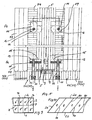
- FIG 4 which is an exploded view of a Frame assembly 1 to 4, the frame parts are 1 to 4 connected at right angles to each other.
- the frame parts are 1 to 4 connected at right angles to each other.
- the lower frame part. 1 and the upper frame part 2 perpendicular to the longitudinal extent the same running board or plate-shaped Intermediate parts 5 arranged, whose function beside the already mentioned increase the bending stiffness of Frame assembly 1 to 4 also consists in receiving spaces. 8 to form for wall units.
- Each wall unit consists of a plate-shaped outer lining element 71, a box-shaped outer wall member 72 and a box-shaped inner wall element 73.
- the outer Wall element 72 is inserted into the frame arrangement 1 from the outside to 4 in between two intermediate parts 5 or between an intermediate part 5 and a lateral frame part 3 or 4 formed receiving space 8 used.
- the inner wall member 73 Accordingly becomes the inner wall member 73 from the inside in said Reception room 8 used, such that the outer Wall member 72 and the inner wall member 73 preferably box and cover-like interlock.
- a insulating, vapor-permeable layer 74 arranged as this is represented by a dotted area.
- the Insulating layer 74 preferably fills said one Interior completely off. A heat release to the outside and a Cold effects inside are thereby prevented.
- at the insulating layer 74 is preferably an insulating biomaterial or commercial Mineral wool.
- the wall elements 72 inserted into the receiving space 8, 73 are closer to forming the wall unit in the later explained manner with each other and with the intermediate parts. 5 or the lateral frame parts 3, 4 connected. It will noted that the dimensions described for the frame assembly 1 to 4 and the wall elements 72, 73 are deliberately chosen so that the box-shaped Wall elements 72, 73 handled by two people and in the Recording rooms 8 can be used.
Abstract
Description
Die Erfindung betrifft ein System zum Erstellen eines
Hauses nach dem Oberbegriff des Patentanspruches 1.The invention relates to a system for creating a
House according to the preamble of
Es sind Fertighäuser bekannt, die aus verschiedenen vorgefertigten Zwischenteilen, Boden- und Deckenelementen bestehen, die bei der Erstellung des Hauses in einer relativ einfachen und zeitsparenden Weise miteinander verbunden werden.There are known prefabricated houses, which consist of different prefabricated intermediate parts, floor and ceiling elements exist in the creation of the house in one relatively simple and time-saving way with each other get connected.
Die Aufgabe der vorliegenden Erfindung besteht darin, ein System zum Erstellen eines Hauses zu schaffen, das in einer einfachen und kostengünstigen Weise errichtbar und wahlweise vergrößerbar oder verkleinerbar ist.The object of the present invention is a To create a system of creating a house in one simple and inexpensive way to build and optionally enlargeable or reducible.
Diese Aufgabe wird durch ein System mit den Merkmalen des
Patentanspruches 1 gelöst.This task is performed by a system with the characteristics of
Für ein lebensangepaßtes Bauen ist es wünschenswert, ein Haus so zu konzipieren, daß es nach den jeweiligen Anforderungen vergrößerbar bzw. verkleinerbar ist. Dies wird vorteilhafterweise durch die vorliegende Erfindung ermöglicht. Genauer gesagt umfasst nach diesem Konzept ein für ein junges Ehepaar gebautes Haus beispielsweise eine Küche, ein Wohnzimmer, ein Esszimmer und ein Schlafzimmer. Wenn im Laufe der Zeit Kinder geboren werden, wird das Haus der Anzahl der Kinder entsprechend um weitere Kinder- bzw. Schlafzimmer erweitert. Wenn beispielsweise der Ehemann ab irgendeinem Zeitpunkt seinen Beruf zuhause ausüben möchte, kann es wünschenswert sein, das Haus um einen Büroraum zu erweitern. Umgekehrt kann es später, wenn die Kinder aus dem Haus sind und der Büroraum wieder entbehrlich wird, vorteilhaft sein, das Haus entsprechend zu verkleinern. Vorteilhafterweise werden dabei zuvor überbaute Grundstücksflächen wieder frei. Die dann künftig anfallenden Heiz- und Bewirtschaftungskosten werden gemäß einem weiteren Vorteil der vorliegenden Erfindung entscheidend reduziert. Nach dem erfindungsgemäßen System errichtete Häuser können somit in einer optimalen Weise genau auf die jeweiligen, sich zeitlich ändernden Bedürfnisse der Besitzer abgestimmt werdenFor a life-adapted building, it is desirable House to design it according to the requirements is enlargeable or reducible. this will advantageously by the present invention allows. More specifically, this concept includes a For example, a house built for a young couple Kitchen, a living room, a dining room and a bedroom. If children are born over time, the house becomes the number of children according to further children or Bedroom expanded. For example, if the husband leaves would like to practice his job at home, It may be desirable to house around an office expand. Conversely, it can be later when the kids are off are the house and the office space becomes unnecessary again, be advantageous to downsize the house accordingly. Advantageously, it is overbuilt beforehand Land areas again free. The then in the future incurred heating and management costs are according to another advantage of the present invention decisively reduced. According to the system of the invention Built houses can thus be in an optimal way exactly on the respective, time-changing Needs of the owners to be matched
Bei einem solchen Konzept ist es wichtig, daß sowohl beim Bau des Hauses, sowie bei der Vergrößerung bzw. Verkleinerung desselben nur wenige Personen, beispielsweise die Hauseigentümer selbst, aus Gründen der Kostenersparnis wichtige Arbeitsschritte, die insbesondere das Aufstellen der Außenwände des Hauses der Räume betreffen, selbst vornehmen können. Dabei werden alle wichtigen Teile durch den Zimmerer mit der entsprechenden Fachkenntnis in der Halle vorgefertigt. Diese vorgefertigten Teile können dann z.B durch den Bauherrn selbst auf der Baustelle montiert werden, wobei hierbei keine grossen Erfahrungen bzw. Fähigkeiten erforderlich sind. Die zusammenzusetzenden Teile bzw. Elemente weisen jeweils ein so kleines Gewicht auf, dass sie ohne weiteres handhabbar sind.In such a concept, it is important that both in the Construction of the house, as well as at the enlargement or Reduction of the same only a few people, for example the homeowners themselves, for reasons of cost savings important steps, in particular the setting up of the exterior walls of the house of the rooms, themselves can make. Thereby all important parts are going through the carpenter with the appropriate expertise in the Hall prefabricated. These prefabricated parts can then For example, by the owner himself mounted on the site be, with no great experience or Skills are required. The zusammenzusetzenden Parts or elements each have such a small weight on that they are easily manageable.
Bei dem vorliegenden System wird bei der Errichtung eines Hauses zunächst eine Primärkonstruktion aus Stützen und Trägern erstellt, die mit der Hilfe von vorzugsweise biegesteifen Anschlüssen verbunden werden und sämtliche statischen Anforderungen erfüllen. Dabei sind die Anschlüsse vorteilhafterweise so beschaffen und vorbereitet, dass nach dem Aufstellen der Stützen die Träger stumpf auf die Stützen stoßen und lediglich mit einer am Träger befestigten Gratplatte in eine entsprechende Grattasche der Stütze eingelassen bzw. eingehängt werden. Die Primärkonstruktion bestimmt die Größe und Form des Hauses. Die Stützen und Träger werden auf ihrer ganzen Länge mit voneinander beabstandeten Rahmen- und Zwischenteilen in der Form von Brettern bzw. Streben versehen, so dass ein Rahmen entsteht, an dem die sogenannte Sekundärkonstruktion in einer einfachen Weise befestigt werden kann. Diese Sekundärkonstruktion besteht aus einzelenen Wandelementen, die von innen und außen in die Zwischenräume zwischen den Zwischenteilen eingesetzt werden. Die Wandelemente besitzen eine modulare Form und sind sowohl beim Bau des Hauses als auch später bei der Vergrößerung bzw. Verkleinerung desselben in einer äußerst einfachen Weise von nur wenigen Personen an der Primärkonstruktion, die den jeweiligen Anforderungen entsprechend verändert wird, montierbar bzw. von dieser demontierbar. Dabei ist dafür Sorge getragen, daß bei der Montage die genannten Verbindungen zwischen der Sekundärkonstruktion und der Primärkonstruktion nahtlos und dicht erfolgen. Vorteilhafterweise sind in die Wandelemente auch isolierende Schichten integriert.In the present system, when establishing a House initially a primary construction of columns and Vehicles created with the help of preferably rigid connections are connected and all meet static requirements. Here are the Connections advantageously and so procured prepared that after putting up the supports the Butt stumpy on the supports and only with a ridge plate attached to the carrier in a appropriate Grattasche the support inserted or be hung. The primary construction determines the Size and shape of the house. The supports and carriers will be spaced along their entire length Frame and intermediate parts in the form of boards or Provided struts, so that a frame is created, where the so called secondary construction in a simple way can be attached. This secondary construction exists from individual wall elements, inside and outside in the spaces between the intermediate parts used become. The wall elements have a modular shape and are both in the construction of the house and later in the Enlargement or reduction of the same in one extreme simple way of only few persons at the Primary construction that meets the respective requirements is changed accordingly, mountable or from this demountable. It is ensured that at the Mounting the mentioned connections between the Secondary construction and primary construction seamless and done tight. Advantageously, in the wall elements also integrated insulating layers.
Es können spezielle Verbindungseinrichtungen (Anschlüsse) zum Verbinden der Wandelemente untereinander bzw. zum Verbinden derselben mit der Primärärkonstruktion und zum Verbinden der Stützen und Träger der Primärkonstruktion verwendet werden, die äußerst einfach und kostengünstig aufgebaut sowie schnell montierbar und demontierbar sind. Special connection devices (connections) for connecting the wall elements with each other or to Connecting the same with the primary construction and Connecting the supports and beams of the primary construction be used, the extremely simple and inexpensive constructed as well as being quickly assembled and disassembled.
Im folgenden werden die Erfindung und deren Ausgestaltungen im Zusammenhang mit den Figuren näher erläutert. Es zeigen:
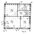
Figur 1- in schematischer Darstellung einen beispielhaften Grundriss des Erdgeschosses eines nach dem erfindungsgemäßen System aufgebauten Hauses;
Figur 2- den beispielhaften Grundriss des Obergeschosses
eines Hauses nach der
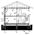
Figur 1; Figur 3- eine Seitenansicht im Schnitt des Hauses gemäß
den
Figuren 1 und 2; Figur 4- eine Explosionsdarstellung der Außenwände des
Hauses der
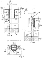
Figuren 1 bis 3; Figur 5- einen Schnitt durch eine Seitenwand des Hauses
gemäß den
Figuren 1 bis 3; Figuren 6 bis 8- bevorzugte Verbindungseinrichtungen; und
- Figuren 9 und 10
- Weiterbildungen der Erfindung.
- FIG. 1
- a schematic plan view of an exemplary floor plan of a built according to the system according to the invention house;
- FIG. 2
- the exemplary floor plan of the upper floor of a house according to the figure 1;
- FIG. 3
- a side view in section of the house according to Figures 1 and 2;
- FIG. 4
- an exploded view of the outer walls of the house of Figures 1 to 3;
- FIG. 5
- a section through a side wall of the house according to Figures 1 to 3;
- FIGS. 6 to 8
- preferred connecting devices; and
- FIGS. 9 and 10
- Further developments of the invention.
Ein nach dem vorliegende System variabel erstellbares Haus
besteht im wesentlichen aus einer Träger 20 und Stützen 40
umfassenden Primärkonstruktion, die die Grösse und Form des
zu erstellenden Hauses festlegen, und einer an der
Primärkonstruktion befestigten Sekundärkonstruktion, die
Rahmenteile 1 bis 4 umfasst, an denen die die Außen- und
Innenwände des Hauses bildenden Wandelemente 72, 73
befestigt werden.A variable building according to the present system
consists essentially of a
Gemäß den Figuren 1 bis 4, die beispielhaft einen Grundriss
des Erdgeschosses (Figur 1) des Hauses, einen Grundriss des
Obergeschosses (Figur 2), eine Seitenansicht im Schnitt und
eine räumliche Darstellung zur Erläuterung der Primär- und
Sekundärkonstruktion zeigen, besteht die
Sekundärkonstruktion eines nach dem erfindungsgemäßen
System aufgebauten Hauses im wesentlichen aus jeweils
unteren Rahmenteilen 1, oberen Rahmenteilen 2, seitlichen
Rahmenteilen 3, 4 und Zwischenteilen 5, die zwischen den
unteren Rahmenteilen 1 und den oberen Rahmenteilen 2
verlaufen (Rahmenanordnungen der Sekundärkonstruktion).
Diese Rahmenteile 1, 2, 3 und 4 sind vorzugsweise direkt an
den Trägern 20 und den Stützen 40 der Primärkonstruktion
befestigt. Die genannten Rahmenteile 1, 2, 3 und 4 sowie
die Zwischenteile 5 weisen vorzugsweise die Form von brett-
bzw. plattenförmigen Teilen auf.According to the figures 1 to 4, which by way of example a floor plan
the ground floor (Figure 1) of the house, a floor plan of
Upper floor (Figure 2), a side view in section and
a spatial representation to explain the primary and
Secondary construction show, there is the
Secondary construction of a according to the invention
System built house essentially from each
Dabei sind mehrere solcher Rahmenanordnungen
zusammengesetzt. Die Zwischenteile 5 tragen zur Steifigkeit
der jeweils gebildeten Rahmenanordnung bei und verhindern
eine Durchbiegung der horizontal verlaufenden Rahmenteile 1
und 2. Die Zwischenteile 5 sind vorzugsweise untereinander
und von den seitlichen Rahmenteilen 3, 4 gleichmäßig
beabstandet, so dass Aufnahmeräume 8 entstehen, in die die
später näher erläuterten Wandelemente 72 und 73 eingesetzt
werden können. Beispielsweise besitzt eine Rahmenanordnung
1 bis 4 zwischen den seitlichen Rahmenteilen 3 und 4 eine
Länge von 3,75 m, wobei die Zwischenteile 5 jeweils 0,625 m
untereinander bzw. 0,625 m von den seitlichen Rahmenteilen
3, 4 beabstandet sind. Wie dies insbesondere aus der Figur
3 ersichtlich ist, weist das vorliegende Haus vorzugsweise
ein sogenanntes Punktfundament auf, das einzelne
Betonelemente 6 umfasst, die in an sich bekannter Weise in
den Untergrund eingelassen sind und die unteren Träger 20
jeweils an ihren Endbereichen abstützen. An nicht außen
liegenden Betonelementen 6 sind jeweils zwei
Rahmenanordnungen 1 bis 4 sowie zwei Träger 20 an einer
Stütze 40 geradlinig aneinandergesetzt. An den Eckbereichen
des Hauses sind jeweils zwei Träger 20 und zwei
Rahmenanordnungen 1 bis 4 rechtwinkelig an einer Stütze 40
aneinander gesetzt.There are several such frame arrangements
composed. The
Gemäß den Figuren 1 bis 3 weist das beispielhaft erläuterte
Haus im Erdgeschoss gemäß Figur 1 einen Bereich
"Wohnen/Kochen/Essen", einen Eingang und einen Bereich
"WC/DU", im Obergeschoss drei Zimmer, einen Flur und ein
Bad auf, wobei das Haus einen quadratischen Grundriss
besitzt. Die Länge L und die Breite B des Hauses (Figur 1)
wird jeweils durch zwei aneinandergesetzte
Rahmenanordnungen 1 bis 4 gebildet. Gemäß der Figur 3
werden die aneinandergesetzten unteren Rahmenelemente 1' in
jeder Richtung durch Träger 20 gestützt, die jeweils durch
drei im Untergrund U angeordnete Betonpfosten 6 gestützt
werden. Das Obergeschoss wird jeweils durch zwei in einer
Richtung nebeneinander angeordnete Rahmenanordnungen 1 bis
4 gebildet, die oberhalb der entsprechenden unteren
Rahmenanordnungen 1 bis 4 angeordnet sind. Die oberen
Rahmenanordnungen 1 bis 4 sind jeweils auf einem oberen
Träger 20 der Primärkonstruktion angeordnet.According to FIGS. 1 to 3, this is explained by way of example
House on the ground floor according to Figure 1 an area
"Living / Cooking / Eating", an entrance and an area
"WC / DU", upstairs three rooms, a hallway and a
Bath on, the house being a square floor plan
has. The length L and the width B of the house (FIG. 1)
is in each case by two juxtaposed
Gemäß Figur 4, die eine Explosionsdarstellung einer
Rahmenanordnung 1 bis 4 zeigt, sind die Rahmenteile 1 bis 4
rechtwinklig miteinander verbunden. In der bereits
erläuterten Weise sind zwischen dem unteren Rahmenteil 1
und dem oberen Rahmenteil 2 senkrecht zur Längserstreckung
derselben verlaufende brett- bzw. plattenförmige
Zwischenteile 5 angeordnet, deren Funktion neben der
bereits angesprochenen Erhöhung der Biegesteifigkeit der
Rahmenanordnung 1 bis 4 auch darin besteht, Aufnahmeräume 8
für Wandeinheiten zu bilden. Jede Wandeinheit besteht aus
einem plattenförmigen äußeren Verkleidungselement 71, einem
kastenförmigen äußeren Wandelement 72 und einem
kastenförmigen inneren Wandelement 73. Das äußere
Wandelement 72 wird von außen her in die Rahmenanordnung 1
bis 4 in einen zwischen zwei Zwischenteilen 5 oder zwischen
einem Zwischenteil 5 und einem seitlichen Rahmenteil 3 oder
4 gebildeten Aufnahmeraum 8 eingesetzt. Entsprechend wird
das innere Wandelement 73 von innen her in den genannten
Aufnahmeraum 8 eingesetzt, derart, dass das äußere
Wandelement 72 und das innere Wandelement 73 vorzugsweise
kasten- und deckelartig ineinander eingreifen. Dabei
übergreifen gemäß Figur 4 die Seitenwände des kastenartigen
äußeren Wandelementes 72 die Seitenwände des kastenartigen
inneren Wandelementes 73 (oder umgekehrt). In dem vom
inneren Wandelement 73 umschlossenen Inneraum ist eine
isolierende, dampfdurchlässige Schicht 74 angeordnet, wie
dies durch eine gepunktete Fläche dargestellt ist. Die
isolierende Schicht 74 füllt vorzugsweise den genannten
Innenraum völlig aus. Eine Wärmeabgabe nach außen und eine
Kälteeinwirkung nach innen werden dadurch verhindert. Bei
der isolierenden Schicht 74 handelt es sich vorzugsweise um
ein isolierendes Biomaterial oder um handelsübliche
Mineralwolle. In dem vom äußeren Wandelement 72
umschlossenen Innenraum ist eine isolierende Schicht
angeordnet, die eine dampfsperrende Wirkung besitzt. Die
Verkleidung 71 wird vorzugsweise nach der Montage des
Wandelementes 72 an der Außenseite desselben befestigt,
zweckmäßigerweise verschraubt oder eingehängt. Sie kann
jedoch auch schon bei der Herstellung der Wandelemente 72
mit diesen verbunden werden.According to Figure 4, which is an exploded view of a
In der insbesondere aus der Figur 5 ersichtlichen Weise
weisen das äußere Wandelement 72 und das innere Wandelement
73 einen jeweils über seine Seitenwände überstehenden
Randbereich 721 bzw. 731 auf, an dem eine ringförmige, die
Seitenwände umgebende Dichtung 9 an der der Rahmenanordnung
1 bis 4 zugewandten Seite angeordnet ist, so dass eine
dichte Verbindung zwischen den den jeweiligen Wandelementen
72, 73 zugewandten Kanten der jeweiligen Bereiche der
unteren und oberen Rahmenteile 1, 2 sowie der Zwischenteile
5 und der seitlichen Rahmenteile 3 bzw. 4 und den
überstehenden Randbereichen 721 bzw. 731 gebildet wird. Bei
den Dichtungen 9 handelt es sich beispielsweise um
ringförmige Schlauchdichtungen oder um ringförmige
Dichtungen, die aus einem dauerplastisch verformbaren
Material bestehen.In the manner shown in particular in Figure 5 way
have the
Die in -einen Aufnahmeraum 8 eingesetzten Wandelemente 72,
73 werden zur Bildung der Wandeinheit in der später näher
erläuterten Weise miteinander und mit den Zwischenteilen 5
bzw. den seitlichen Rahmenteilen 3, 4 verbunden. Es wird
darauf hingewiesen, dass die beschriebenen Dimensionen für
die Rahmenanordnung 1 bis 4 und die Wandelemente 72, 73
bewußt so gewählt sind, dass die kastenförmigen
Wandelemente 72, 73 von zwei Personen gehandhabt und in die
Aufnahmeräume 8 eingesetzt werden können.The
Es ist gemäß Figur 9 auch denkbar, die Wandelemente 72 und
73 dadurch kleiner und leichter zu gestalten, dass die
Aufnahmeräume 8 durch in Längsrichtung verlaufende,
vorzugsweise brett- oder plattenförmige Zwischenelemenet 7
unterteilt werden, sodass kleinere, vorzugsweise zwei
gleich große Aufnahmeräume 8' und 8" entstehen.It is also conceivable according to FIG. 9, the
Gemäß der Figur 10 werden die Böden des Hauses vorzugsweise
ebenfalls mit der Hilfe der erläuterten kastenförmigen
Wandelenmente 72, 73 gebildet. Dabei wird der von vier
Trägern 20 umschlossene Raum durch parallel zueinander
angeordnete Nebenträger 60 in Zwischenräume 8 unterteilt,
in die von oben bzw. unten Wandelemente 72, 73 in der oben
bereits beschriebenen Weise eingesetzt werden. Die von oben
eingesetzten Wandelemente bilden den Boden und die von
unten eingesetzten Wandelemente die Decke eines Zimmers des
Hauses. Auf den den Boden bildenden Wandelementen können
übliche Bodenbeläge, wie z.B. Teppichware, Parkett oder
Fliesen verlegt werden.According to FIG. 10, the floors of the house are preferably
also with the help of the explained box-shaped
Ein besonderer Vorteil der vorliegenden Erfindung besteht
auch darin, dass nach der Erstellung des Hauses ein relativ
einfaches Verlegen von Leitungen dadurch möglich ist, dass
die zu verlegenden Leitungen nach Abnahme insbesondere der
inneren Wandelemente 73 in die dann freiliegenden Räume
eingebracht und verlegt werden.A particular advantage of the present invention is
also in that after the creation of the house a relative
easy laying of cables is possible by that
the cables to be laid after acceptance, in particular the
Die Figur 5 zeigt eine bevorzugte Art der Befestigung der
Wandelemente 72, 73 an den Zwischenteilen 5 in vergrößerter
Darstellung, wobei die Figur 5a einen Horizontalschnitt
durch die fertig montierten Wandelemente 72, 73, und die
Figur 5b einen entsprechenden vertikalen Schnitt zeigen.FIG. 5 shows a preferred way of attaching the
In der ersichtlichen Weise erfolgt die Befestigung mit der
Hilfe von Schrauben 11, die in Bohrungen 12 eingesetzt
werden, die ausgehend von der Stirnseite 722 bzw. 732 des
Wandelementes 72 bzw. 73 bis zu einer sich im
Montagezustand in Richtung auf die Mittelwand 5 öffnenden
Aussparung 13 verläuft. Der Aussparung 13 im Montagezustand
gegenüberliegend befindet sich in dem Zwischenteil 5 eine
Aussparung 15, die sich zur Aussparung 13 hin öffnet. In
der Aussparung 13 ist eine Metallplatte 14 mit einer
Bohrung 16 mit einem Innengewinde angeordnet, in der die
Schraube 11 zur Montage des Wandelementes 72 bzw. 73 an dem
Zwischenteil 5 verschraubt wird. Die Metallplatte 14 wird
zuvor aus dem in der Figur 5b dargestellten Zustand, in dem
sie sich vollständig in der Aussparung 13 befindet, bei der
Schrauboperation in den Zustand verschwenkt, in dem sie
teilweise gemäß Figur 5b in die Aussparung 15 eingreift.
Beim Verschrauben wird daher das Wandelement 72 bzw. 73 in
Richtung auf das Zwischenteil 5 gezogen, wobei die Dichtung
9 zwischen dem Randbereich der Stirnseite 722 bzw. 732 und
der Stirnseite des Zwischenteiles 5 zusammengedrückt wird
und ihre Dichtwirkung entfaltet. Den Aussparungen 15 der
Zwischenteile 5 entsprechende Aussparungen sind auch in den
seitlichen Rahmenteilen 3, 4 vorgesehen.In the apparent manner, the attachment takes place with the
Help from
In der aus der Figur 4 ersichtlichen Weise werden die
unteren Rahmenteile 1 an unteren Rahmenelementen 1', die
oberen Rahmenteile 2 an oberen Rahmenelementen 2' und die
seitlichen Rahmenteile 3, 4 an seitlichen Rahmenelementen
3' bzw. 4' befestigt, die Teil der Primärkonstruktion sind
und an den Stützen 40 bzw. Trägern 20 befestigt sind.
Nachfolgend wird nun eine besonders bevorzugte Art der
Erstellung sowie der Verbindung der Stützen 40 und Träger
20 der Primärkonstruktion im Zusammenhang mit den Figuren 6
bis 8 näher erläutert. Zunächst werden in dem Fundament F
Sützen 40 an den gewünschten Orten angeordnet. Die Stützen
40 umfassen in der Höhe der anzubringenden Träger 20
vorzugsweise ein vorzugsweise aus Stahl bestehendes
kastenartiges Trägerteil 43 mit einem rechteckigen,
vorzugsweise quadratischen Hohlprofil, an dem an zwei sich
gegenüberliegenden Seiten nach oben und nach unten
verlängerte Seitenteile 41, die an einer Seite in das
Fundament F eingelassen werden, verschweißt sind. Bis etwa
zur halben Höhe des Trägerteiles 43 wird ein quer zu den
Verlängerungen 41 verlaufendes, vorzugsweise bandförmiges
Eisenteil 42 zwischen die Verlängerungen 41 eingeschweißt,
das ebenfalls in das Fundament F hineinverläuft und eine
Kräfteaufnahme in beiden Richtungen ermöglicht. Das Teil
43 weist eine Länge auf, die etwa der Dicke der
anzuschließenden Träger 20 entspricht.In the manner shown in Figure 4, the
Damit der Bauherr in besonders einfacher Weise an das
Trägerteil 43 rundum, d.h. also auf allen vier Seiten der
Stütze 40 jeweils einen Träger 20 anschließen kann, ist
zweckmäßigerweise an jeder der vier Seiten des Trägerteiles
43 eine Halteplatte 44 aufgeschweißt, die eine
Aufnahmetasche 45 für ein Einsteckteil 46 einer an dem
Träger 20 befestigten Montageplatte 47 besitzt.
Vorzugsweise ist die Montageplatte 47 Teil eines U-förmigen
Flachstahlteiles, das die Stirnseite des Trägers 20 fest
umschließt. Vorzugsweise weist das an der Montageplatte 47
verschweißte Einsteckteil 46 die Form einer sogenannten
Gratplatte auf, die in die nach oben geöffnete
Aufnahmetasche 45 in der Form einer Grattasche zur
Befestigung des Trägers 20 an der Stütze 40 von oben her
eingelassen bzw. eingehängt wird. Es sind keine Schrauboder
Dübelverbindungen erforderlich.So that the builder in a particularly simple manner to the
In der beschriebenen Weise können alle Knoten zwischen
allen Trägern 20 aller Etagen des Hauses und den Stützen 40
zur Erstellung der Primärkonstrktion hergestellt werden.In the manner described, all nodes can be between
all
Claims (14)
Applications Claiming Priority (2)
| Application Number | Priority Date | Filing Date | Title |
|---|---|---|---|
| DE2003145760 DE10345760A1 (en) | 2003-10-01 | 2003-10-01 | System for building houses |
| DE10345760 | 2003-10-01 |
Publications (2)
| Publication Number | Publication Date |
|---|---|
| EP1520944A2 true EP1520944A2 (en) | 2005-04-06 |
| EP1520944A3 EP1520944A3 (en) | 2006-03-15 |
Family
ID=34306190
Family Applications (1)
| Application Number | Title | Priority Date | Filing Date |
|---|---|---|---|
| EP04023431A Withdrawn EP1520944A3 (en) | 2003-10-01 | 2004-10-01 | Method for constructing houses |
Country Status (2)
| Country | Link |
|---|---|
| EP (1) | EP1520944A3 (en) |
| DE (1) | DE10345760A1 (en) |
Cited By (2)
| Publication number | Priority date | Publication date | Assignee | Title |
|---|---|---|---|---|
| EP1717452A1 (en) | 2005-04-28 | 2006-11-02 | Udo Vierck | Device for connecting two construction elements |
| FR3031351A1 (en) * | 2015-01-07 | 2016-07-08 | Patrick Gehin | SYSTEM OR NODE FOR ASSEMBLING AND FIXING BUILDING ELEMENTS |
Citations (5)
| Publication number | Priority date | Publication date | Assignee | Title |
|---|---|---|---|---|
| US3315426A (en) * | 1963-04-09 | 1967-04-25 | Robert C Rolland | Prefabricated wall structure |
| US3921362A (en) * | 1974-03-18 | 1975-11-25 | Pablo Cortina Ortega | Method of and means for multi-story building construction |
| US4539788A (en) * | 1982-05-13 | 1985-09-10 | Adviesbureau D3Bn Civiel Ingenieurs | Method of building a house starting from a packaged structure, a packaged structure for use in said method, a method of making a foundation, and a pile cap for use therein |
| US4555890A (en) * | 1981-10-15 | 1985-12-03 | Josef Gartner & Co. | Process for the installation of curtain walls and apparatus for the execution of the process |
| EP0953697A2 (en) * | 1998-03-31 | 1999-11-03 | A. Jandl Patentholding KEG | House |
-
2003
- 2003-10-01 DE DE2003145760 patent/DE10345760A1/en not_active Withdrawn
-
2004
- 2004-10-01 EP EP04023431A patent/EP1520944A3/en not_active Withdrawn
Patent Citations (5)
| Publication number | Priority date | Publication date | Assignee | Title |
|---|---|---|---|---|
| US3315426A (en) * | 1963-04-09 | 1967-04-25 | Robert C Rolland | Prefabricated wall structure |
| US3921362A (en) * | 1974-03-18 | 1975-11-25 | Pablo Cortina Ortega | Method of and means for multi-story building construction |
| US4555890A (en) * | 1981-10-15 | 1985-12-03 | Josef Gartner & Co. | Process for the installation of curtain walls and apparatus for the execution of the process |
| US4539788A (en) * | 1982-05-13 | 1985-09-10 | Adviesbureau D3Bn Civiel Ingenieurs | Method of building a house starting from a packaged structure, a packaged structure for use in said method, a method of making a foundation, and a pile cap for use therein |
| EP0953697A2 (en) * | 1998-03-31 | 1999-11-03 | A. Jandl Patentholding KEG | House |
Cited By (2)
| Publication number | Priority date | Publication date | Assignee | Title |
|---|---|---|---|---|
| EP1717452A1 (en) | 2005-04-28 | 2006-11-02 | Udo Vierck | Device for connecting two construction elements |
| FR3031351A1 (en) * | 2015-01-07 | 2016-07-08 | Patrick Gehin | SYSTEM OR NODE FOR ASSEMBLING AND FIXING BUILDING ELEMENTS |
Also Published As
| Publication number | Publication date |
|---|---|
| EP1520944A3 (en) | 2006-03-15 |
| DE10345760A1 (en) | 2005-04-21 |
Similar Documents
| Publication | Publication Date | Title |
|---|---|---|
| EP3366854A1 (en) | Prefabricated house | |
| DE7934285U1 (en) | BUILDING UNIT FOR BUILDING BUILDINGS | |
| DE2929197C2 (en) | Open skeleton frame element made of reinforced concrete | |
| EP1273729A2 (en) | Element of brick material for making prefabricated panels for the construction industry | |
| WO2014060155A1 (en) | Building system, particularly a residential building | |
| DE3443938A1 (en) | Prefabricated compound unit | |
| EP1520944A2 (en) | Method for constructing houses | |
| DE10005872C1 (en) | Room cell for modular building construction has self-supporting frame enclosing rectabgular room space fitted with floor and ceiling panels an one or more external or internal wall panels | |
| DE2445443A1 (en) | Air conditioning plant - interlocking insulated hollow walling components, with two parallel croarms engaged by part of next component, and intermediate groove | |
| EP0955419B1 (en) | Framework system for prefabricated buildings | |
| EP1705302A2 (en) | Element of brick material for making prefabricated panels for the construction industry | |
| DE4411004A1 (en) | Modular house | |
| AT402417B (en) | THERMALLY INSULATED BUILDING | |
| EP0120292A2 (en) | Construction element | |
| DE2322920C3 (en) | Prefabricated component for the manufacture of buildings | |
| DE1302180C2 (en) | PROCEDURE FOR ERECTING A MULTI-STOREY BUILDING AND BUILDING ESTABLISHED BY THE PROCEDURE | |
| DE4328236C2 (en) | Prefabricated building | |
| EP0717158B1 (en) | System of constructional volumes for the erection of buildings | |
| DE1459901C3 (en) | Building that has a front with loggias | |
| DE19629786A1 (en) | Building module | |
| AT513397B1 (en) | Support structure for a building construction and building construction | |
| DE2342046A1 (en) | MULTI-STORY PRE-FABRICATED BUILDING | |
| DE2037472C3 (en) | Building in cellular construction with a hexagonal grid | |
| DE2342883C3 (en) | External wall construction made of large panel elements | |
| DE1609361C3 (en) | Buildings with prefabricated, closed, single-cell frame elements made of reinforced concrete |
Legal Events
| Date | Code | Title | Description |
|---|---|---|---|
| PUAI | Public reference made under article 153(3) epc to a published international application that has entered the european phase |
Free format text: ORIGINAL CODE: 0009012 |
|
| AK | Designated contracting states |
Kind code of ref document: A2 Designated state(s): AT BE BG CH CY CZ DE DK EE ES FI FR GB GR HU IE IT LI LU MC NL PL PT RO SE SI SK TR |
|
| AX | Request for extension of the european patent |
Extension state: AL HR LT LV MK |
|
| PUAL | Search report despatched |
Free format text: ORIGINAL CODE: 0009013 |
|
| AK | Designated contracting states |
Kind code of ref document: A3 Designated state(s): AT BE BG CH CY CZ DE DK EE ES FI FR GB GR HU IE IT LI LU MC NL PL PT RO SE SI SK TR |
|
| AX | Request for extension of the european patent |
Extension state: AL HR LT LV MK |
|
| RIC1 | Information provided on ipc code assigned before grant |
Ipc: E04B 1/35 20060101ALI20060124BHEP Ipc: E04B 1/24 20060101AFI20060124BHEP |
|
| RAP1 | Party data changed (applicant data changed or rights of an application transferred) |
Owner name: VIERCK, UDO |
|
| RIN1 | Information on inventor provided before grant (corrected) |
Inventor name: VIERCK, UDO |
|
| 17P | Request for examination filed |
Effective date: 20060907 |
|
| AKX | Designation fees paid |
Designated state(s): AT BE BG CH CY CZ DE DK EE ES FI FR GB GR HU IE IT LI LU MC NL PL PT RO SE SI SK TR |
|
| 17Q | First examination report despatched |
Effective date: 20070308 |
|
| STAA | Information on the status of an ep patent application or granted ep patent |
Free format text: STATUS: THE APPLICATION HAS BEEN WITHDRAWN |
|
| 18W | Application withdrawn |
Effective date: 20070623 |