EP1520815A1 - Vakuumtransportvorrichtung, insbesondere als Materialbahneinfädeleinrichtung in einer Maschine zur Herstellung oder/und Veredelung einer Materialbahn - Google Patents
Vakuumtransportvorrichtung, insbesondere als Materialbahneinfädeleinrichtung in einer Maschine zur Herstellung oder/und Veredelung einer Materialbahn Download PDFInfo
- Publication number
- EP1520815A1 EP1520815A1 EP04104054A EP04104054A EP1520815A1 EP 1520815 A1 EP1520815 A1 EP 1520815A1 EP 04104054 A EP04104054 A EP 04104054A EP 04104054 A EP04104054 A EP 04104054A EP 1520815 A1 EP1520815 A1 EP 1520815A1
- Authority
- EP
- European Patent Office
- Prior art keywords
- conveyor belt
- vacuum
- sections
- belts
- conveyor belts
- Prior art date
- Legal status (The legal status is an assumption and is not a legal conclusion. Google has not performed a legal analysis and makes no representation as to the accuracy of the status listed.)
- Granted
Links
- 239000000463 material Substances 0.000 title claims description 81
- 239000011111 cardboard Substances 0.000 claims abstract description 3
- 239000011087 paperboard Substances 0.000 claims abstract description 3
- 230000033001 locomotion Effects 0.000 claims description 21
- 230000005540 biological transmission Effects 0.000 claims description 8
- 238000004519 manufacturing process Methods 0.000 abstract description 4
- 239000000123 paper Substances 0.000 description 11
- 230000008878 coupling Effects 0.000 description 6
- 238000010168 coupling process Methods 0.000 description 6
- 238000005859 coupling reaction Methods 0.000 description 6
- 238000010276 construction Methods 0.000 description 2
- 238000006073 displacement reaction Methods 0.000 description 2
- 230000009467 reduction Effects 0.000 description 2
- 238000007670 refining Methods 0.000 description 2
- 230000001360 synchronised effect Effects 0.000 description 2
- 238000012546 transfer Methods 0.000 description 2
- 230000008901 benefit Effects 0.000 description 1
- 230000008859 change Effects 0.000 description 1
- 239000011248 coating agent Substances 0.000 description 1
- 238000000576 coating method Methods 0.000 description 1
- 238000013461 design Methods 0.000 description 1
- 238000009499 grossing Methods 0.000 description 1
- 238000010348 incorporation Methods 0.000 description 1
- 238000009434 installation Methods 0.000 description 1
- 230000007257 malfunction Effects 0.000 description 1
- 238000000034 method Methods 0.000 description 1
- 230000002093 peripheral effect Effects 0.000 description 1
- 230000035699 permeability Effects 0.000 description 1
- 230000008569 process Effects 0.000 description 1
- 230000001737 promoting effect Effects 0.000 description 1
- 230000001902 propagating effect Effects 0.000 description 1
- 230000003134 recirculating effect Effects 0.000 description 1
- 230000008719 thickening Effects 0.000 description 1
- 238000012549 training Methods 0.000 description 1
- 230000007704 transition Effects 0.000 description 1
- 230000007306 turnover Effects 0.000 description 1
Images



Classifications
-
- B—PERFORMING OPERATIONS; TRANSPORTING
- B65—CONVEYING; PACKING; STORING; HANDLING THIN OR FILAMENTARY MATERIAL
- B65H—HANDLING THIN OR FILAMENTARY MATERIAL, e.g. SHEETS, WEBS, CABLES
- B65H20/00—Advancing webs
- B65H20/10—Advancing webs by a feed band against which web is held by fluid pressure, e.g. suction or air blast
-
- D—TEXTILES; PAPER
- D21—PAPER-MAKING; PRODUCTION OF CELLULOSE
- D21G—CALENDERS; ACCESSORIES FOR PAPER-MAKING MACHINES
- D21G9/00—Other accessories for paper-making machines
- D21G9/0063—Devices for threading a web tail through a paper-making machine
-
- B—PERFORMING OPERATIONS; TRANSPORTING
- B65—CONVEYING; PACKING; STORING; HANDLING THIN OR FILAMENTARY MATERIAL
- B65H—HANDLING THIN OR FILAMENTARY MATERIAL, e.g. SHEETS, WEBS, CABLES
- B65H2406/00—Means using fluid
- B65H2406/30—Suction means
- B65H2406/32—Suction belts
Definitions
- the present invention relates to a machine for manufacturing or / and finishing a running material web, in particular of paper or cardboard, which has a at least partially non-straight material web path defining Material web guide and an associated, possibly with the material web guide cooperating web threading device, wherein by means of Materialbahneinfädel adopted a running threading material web section in Assignment to Materialbahnweg at least one deflection of the Material web path deflected by a deflection angle and the web path is associated with conveyed, and wherein the material web threading device with a Vacuum conveyor belt assembly is executed.
- a Vacuum conveyor belt arrangement can be used, which, for example, from EP 1 205 415 is known.
- a vacuum conveyor belt arrangement comprises two Pulleys, a guided around the pulleys conveyor belt and a Suction device.
- the conveyor belt is permeable to air, so that a through the suction device applied to the inside of the conveyor belt vacuum can propagate through the conveyor belt and a threading material web section to be conveyed sucked on the outside of the conveyor belt.
- the threading material web section is then moved in the direction of Vacuum conveyor belt arrangement moves.
- the material web path runs along a deflection point, for example around one Deflection pulley around, so it is necessary to the threading material web section in Assignment to the web path to deflect the deflection also.
- air baffles are used which run along one the conveying path of the threading material web section curved around the deflection Surface having arranged on this surface air nozzles, which is substantially in Direction of the conveying path of the threading material web section eject compressed air.
- the threading material web section slides on a Air cushion along the curved surface of the baffle around the deflection point and can then, for example, by a subsequently arranged Vacuum conveyor belt assembly are further promoted.
- successive vacuum conveyor belt sections are respectively at an angle ⁇ 180 ° to each other. But it is not excluded that in an arrangement of several vacuum conveyor belt sections some Vacuum conveyor belt sections at an angle of about 180 ° to each other run and possibly through a longer continuous vacuum conveyor belt section could be replaced.
- the vacuum transport sections are preferably of at least two Deflection rollers guided conveyor belts and through the conveyor belts or / and sucking between adjacent conveyor belts Suction arrangements formed.
- the vacuum conveyor belt sections from a respective vacuum conveyor belt are formed, the at least two pulleys, at least one around the pulleys guided conveyor belt and one through the conveyor belt or between comprising suction arrangement sucking adjacent conveyor belts.
- At least one pair of adjoining ones Vacuum conveyor belt sections have a common pulley on the at least one accumulating conveyor belt of the rear in the conveying direction Vacuum conveyor belt section and at least one running conveyor belt of the Conveying direction front vacuum conveyor belt section is performed.
- a number of n successively arranged pulleys by a number of (n-1) conveyor belts each circulating two adjacent pulleys a vacuum conveyor belt assembly are formed, which are using from as few pulleys the threading web section on the Deflecting point deflects.
- At least one Vacuum conveyor belt section with at least one permeable conveyor belt is formed and that the suction arrangement by the permeable conveyor belt through the threading material web section sucks.
- At least one conveyor belt of several is formed next to each other extending conveyor belt.
- the suction assembly can in this case in a space between adjacent conveyor belts suck.
- two Vakuumtransportbandabitese can be provided be that on the common pulley, viewed in the axial direction, a accumulating conveyor belt or an accumulating conveyor belt between two running conveyor belts or running conveyor belt and / or a running conveyor belt or an expiring conveyor belt between two accumulating conveyor belts or two accumulating conveyor belt arranged is.
- running up Conveyor belts and running conveyor belts or accumulating conveyor belts and expiring conveyor belts alternately at least in sections are arranged.
- At least one of the vacuum conveyor belt sections is adjustable so that the angle at which the vacuum conveyor belt section relative to the other vacuum conveyor belt sections runs, is changeable, whereby the vacuum conveyor belt assembly for use at different deflection points with correspondingly different deflection angles can be adjusted.
- Vacuum conveyor belt sections associated conveyor belts motion coupled are and can be driven by at least one common drive unit.
- Conveyor belts via a belt transmission, a gear transmission or like between at least two pulleys different vacuum conveyor belt sections are drivable and motion coupled. The latter is especially then conceivable if the vacuum conveyor belt arrangement is an arrangement conventional trained vacuum conveyor belt sections, each with two own pulleys includes.
- the present invention also relates to a vacuum transport device for web or Sheet material, in particular as a material web threading device for a machine of the type described above, for conveying the web or sheet material, optionally a threading material web section, along a conveying path, comprising at least one vacuum conveyor belt section with at least one order at least two pulleys guided conveyor belt and a through the at least one conveyor belt through and / or between juxtaposed Conveyor belts sucking suction arrangement.
- a vacuum transport device for web or Sheet material in particular as a material web threading device for a machine of the type described above, for conveying the web or sheet material, optionally a threading material web section, along a conveying path, comprising at least one vacuum conveyor belt section with at least one order at least two pulleys guided conveyor belt and a through the at least one conveyor belt through and / or between juxtaposed Conveyor belts sucking suction arrangement.
- Such Vacuum transport device further comprises a Vacuum conveyor belt assembly with a plurality of adjoining, itself together around a deflection extending vacuum conveyor belt sections, wherein the web or sheet material, optionally the threading material web section from vacuum conveyor belt section to vacuum conveyor belt section is convertible and by vacuum conveyor belt sections extending at an angle of less than 180 degrees to each other to a respective partial deflection angle of a deflection angle of the Deflection is deflectable.
- Vacuum conveyor belt sections formed by a respective vacuum conveyor belt are, at least two pulleys, at least one guided around the pulleys Conveyor belt and a through the conveyor belt or between comprising suction arrangement sucking adjacent conveyor belts. Accordingly, in this embodiment, the vacuum transport device an implementation of the invention using conventional vacuum conveyor belt sections allows for a flexible use and possibly a inexpensive construction of the device allows.
- At least one pair of themselves adjoining vacuum conveyor belt sections a common Have pulley over the at least one accumulating conveyor belt of Conveying direction rear vacuum conveyor belt section and at least one running conveyor belt of the front in the conveying direction Vacuum conveyor belt section is guided, wherein at least one conveyor belt of may be formed a plurality of adjacent conveyor belt.
- the suction arrangements several, preferably all Vacuum transport sections to a common vacuum source or also at each internal, preferably within the conveyor belts and / or within the Vacuum conveyor belt sections arranged vacuum sources connectable or are connected. At least one of the vacuum transport sections may be so be adjustable so that the angle at which the vacuum transport section relative to the other vacuum conveyor belt sections runs, is changeable.
- Fig. 1 shows as an example of a paper finishing machine a Janus calender for Smoothing or structuring of the surface of a paper web.
- a spreader roll 20 supplied, to be finished material web 10 repeats a Contact area (Nip 14) of two converging calender rolls 12.
- Die Spreader roller 20 has a slightly curved surface to the above consistently spread material web across its entire width.
- the Calender rolls 12 are parallel to each other in a vertical row aligned axes, so that the nips 14 between adjacent Calender rolls 12 are also arranged in a vertical line with each other.
- the material web 10 is then, as shown in Fig. 1, successively through the nips 14th guided.
- the paper guide rollers 16 therefore form a deflection point of the web path on which the web of material from one of the Kalanderwalzen leading away direction in one on the calender rolls feeding direction is deflected.
- a Materialbahneinfädel worn To a leading end of a web at startup of the machine or to thread into the machine after a tearing of the material web is a Materialbahneinfädel issued provided. This captures a threading material web section by means of a first vacuum conveyor belt 18 and guides it first via the spreader roll 20. Subsequently, the threading material web section detected by a second vacuum conveyor belt 22 through which the threading web portion in the direction of the opened nip 14th between two first of the calender rolls 12 is guided. After going through the Nip 14 becomes the threading web portion of another vacuum conveyor belt 24 detected, which this to the deflection point forming paper guide roller 16th leads.
- Threading the threading web section in this area means a Passing the threading material web section around the paper guide roller 16 up to a region in which the threading material web section from another Vacuum conveyor belt 26 can be detected, which the threading material web section then the next (now open) nip 14 of the next Calender roll pair 12 feeds.
- the paper guide roller 16 therefore forms a deflection point, at which the threading material web section is deflected, wherein as the deflection angle approximately at an included by the vacuum conveyor belts 24 and 26 angle can be viewed.
- a vacuum transport arrangement for conveying the threading material web section in the region of the deflection point around the Paper guide roller 16 may be a vacuum transport arrangement according to the invention used which are generally designated 30 and in Fig. 1 only schematically is shown. After deflecting the threading material web section of this is on analogous manner with the help of further vacuum conveyor belts 26, 28, 32, 34 by further Nips 14 out and deflected at more paper guide 16. From illustrative For reasons in Fig. 1 in the region of the second paper guide roller 16 a per se known air baffle 36 located, which the threading material web section by air jets emerging from nozzles 38 along the curved surface 40 of the air guide plate 36 around the paper guide roller 16 leads around.
- the vacuum conveyor belts 22-34 each have one Drive unit 42, which with one of the deflection rollers 44 by a Belt transmission is motion coupled.
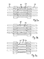
- a first embodiment of the vacuum conveyor belt arrangement according to the invention 30 will be described below with reference to FIGS. 2a and 2b. It will become one Threading material web section approximately along the marked by the arrows Promoted way and first from a first vacuum conveyor belt section 46th detected, transferred from this to a second vacuum conveyor belt section 48, which in turn the threading material web section to a third vacuum conveyor belt section 50 hands over.
- Vakuumtransportbandabterrorismen is the threading material web section to a Deflection angle á or ä deflected, each of the deflection angle á, ä a partial deflection angle of the deflection angle ⁇ , which is essentially determined by the relative Alignment of the first and the last vacuum conveyor belt section is determined.
- the angles á and ä do not have to be the same size and can be used standing installation space of the machine in the area of the deflection point or other Be adapted to circumstances.
- each vacuum conveyor belt section 46, 48, 50 in the in Fig. 2a and 2b a respective number of transport belts 52, 54, 56, which in each case by two adjacent deflection rollers of an arrangement of four Axially parallel guide rollers 58, 60, 62, 64 are guided.
- a drive unit 66 For driving the transport belt 52, 54, 56 with a desired Threading speed is a drive unit 66 is provided which one with a Motor 68 connected pulley 70 includes.
- a Motor 68 connected pulley 70 By means of the belt 72 is the Rotary movement of the pulley 70 then on one with the axis of the first Guide pulley 58 rotatably connected pulley 74 transmit, which finally the belt 52 of the first vacuum conveyor belt section 46 drives.
- the subsequent vacuum conveyor belt sections 48 and 50 are with the first Vacuum conveyor belt section 46 via the common pulleys 60, 62nd motion coupled, so that a drive of the first guide roller 58 is a synchronous Rotary movement of all four pulleys 58, 60, 62, 64 and thus a synchronous Movement of all three transport belt sets 52, 54, 56 causes.
- a suction device is provided, which each between two adjacent pulleys 58, 60, 62, 64 arranged Vacuum boxes 76, 78, 80 includes.
- the vacuum boxes 76, 78, 80 have at their the threading material web section to be conveyed facing surface side Air openings through which air sucked into the vacuum boxes 76, 78, 80 which sucks the threading material web section.
- the negative pressure in the vacuum boxes 76, 78, 80 is maintained by a Vacuum source, not shown (e.g., an electric or air driven turbine or a Venturi nozzle) via a line system schematically indicated 82 and individual vacuum lines 84 to the respective vacuum boxes 76, 78, 80th connected is.
- a Vacuum source not shown (e.g., an electric or air driven turbine or a Venturi nozzle) via a line system schematically indicated 82 and individual vacuum lines 84 to the respective vacuum boxes 76, 78, 80th connected is.
- a Vacuum source not shown (e.g., an electric or air driven turbine or a Venturi nozzle) via a line system schematically indicated 82 and individual vacuum lines 84 to the respective vacuum boxes 76, 78, 80th connected is.
- the suction arrangement in particular their air openings, in relation on the course of the conveyor belt 52, 54, 56, three examples according to Fig. 3a to 3c.
- the air openings 81 formed as extending obliquely to the conveying direction slot openings.
- One according to This example of a suction arrangement is very flexible since it is not preferred Determines position for the belt 54 and possibly also for use with a permeable conveyor belt is suitable.
- FIG. 3 b is aligned in the conveying direction Air opening slots 81 ', which in each case in the space between are arranged side by side extending conveyor belt 54.
- Air opening slots 81 ' which in each case in the space between are arranged side by side extending conveyor belt 54.
- the available area between the conveyor belt 54 is optimal exploited.
- FIG. 3c Another conceivable example of the arrangement of the air openings is shown in Fig. 3c shown.
- the air opening slots 81 "are also in the conveying direction aligned, but provided below the conveyor belt 54 extending.
- the transport belts should have a certain air permeability around propagating the negative pressure from the vacuum box 78 through the Transport belt through for sucking the threading material web section enable.
- a second embodiment of the invention will be described below with reference to FIG Fig. 4a and 4b described. Similar to the first embodiment trained components are provided with increased by 100 reference numerals and will not be described again.
- the three vacuum conveyor belt sections 146, 148 and 150 each include one separate pair of pulleys 158, 159, 160, 161, 162 and 163, each of a conveyor belt 152, 154 and 156 are circulated. Since the conveyor belts 152, 154, 156 of adjacent vacuum conveyor belt sections 146, 148, 150 not about one be deflected common pulley, it is possible, the conveyor belts 152, 154, 156 over substantially the entire length of the pulleys 158-163 to expire.
- the width of the conveyor belts 152, 154, 156 be at least as wide as the width of a threading material web section, so that a secure support of the threading material web section is ensured on the vacuum conveyor belt assembly.
- an arrangement of transport belts in a described for the first embodiment Way is used instead of the conveyor belts 152, 154, 156.
- a drive unit 166 with a motor 168 and an associated Pulley 170 may be provided, which via a drive belt 172 a Guide roller 158 drives.
- the guide roller 158 but also by a internal drive, for example by a within the pulley 158th arranged motor, to be driven.
- a belt transmission between adjacent arranged pulleys adjacent vacuum conveyor belt sections be provided. These are at the ends of the respective pulleys 159-162 one each or a plurality of motion coupling pulleys 186 and motion coupling pulleys adjacent pulleys 159 to 162 different Vacuum conveyor belt sections 146, 148, 150 and are of a Recirculating coupling belt 188.
- vacuum boxes 176, 178, 180 used for this purpose at her the threading material web section facing side formed with air openings and the Conveyor belts 152, 154, 156 are permeable to air, so that in the Vacuum boxes 176, 178, 180 generated negative pressure, the air openings and through the conveyor belts 152, 154, 156 propagates to the threading material to be conveyed train section to suck.
- a tension roller 192 can also be seen, which is a possibility to illustrate, for a conveyor belt 156 a vacuum conveyor belt assembly according to the invention set or maintain a predetermined target voltage. Due to the juxtaposition of Vakuumtransportbandabitesen it can in Both embodiments be made difficult by a shift of the pulleys 58th to set 64, 158-163 a target voltage in a conventional manner or maintain.
- an additional tensioning roller 194 can, as for the Conveyor belt 156 illustrated in FIGS. 4a and 4b, a setpoint tension is set, by the tension roller 192 relative to the connecting line between the guide rollers 162 and 163 is displaced so that the circulation path of the conveyor belt is increased or is reduced.
- Such a tensioning roller 192 can of course be analogous to several or all conveyor belts 152, 154, 156 each for one or more of Transport belt 52, 54, 56 may be provided.
- a tensioning of the conveyor belts or belts by enlargement or Reduction of the circulation path using tension rollers makes it possible Furthermore, the arrangement of the pulleys 58 to 64, 158 to 163 according to a desired deflection angle or according to space conditions in the area the deflection of the machine to provide flexible adjustable because of compliance a fixed distance between two of a conveyor belt or belt revolved pulleys do not have to be respected. That way you can not only the orientations of the individual vacuum conveyor belt sections but also whose lengths are made adjustable in the direction of the conveying path.
- a vacuum conveyor belt assembly according to that shown in Figs. 4a and 4b second embodiment of the invention also offers the advantage that it is possible to Vacuum conveyor belt assembly according to the invention using conventional Produce vacuum conveyor belts with simple means by these suitable arranged and with movement coupling pulleys 186 and these circulating movement coupling belt 188 are equipped, resulting in a modular, flexibly changeable design results.
Landscapes
- Physics & Mathematics (AREA)
- Fluid Mechanics (AREA)
- Advancing Webs (AREA)
- Blow-Moulding Or Thermoforming Of Plastics Or The Like (AREA)
- Organic Low-Molecular-Weight Compounds And Preparation Thereof (AREA)
- Processing And Handling Of Plastics And Other Materials For Molding In General (AREA)
- Replacement Of Web Rolls (AREA)
- Registering, Tensioning, Guiding Webs, And Rollers Therefor (AREA)
Abstract
Description
Claims (27)
- Maschine zur Herstellung oder/und Veredelung einer laufenden Materialbahn, insbesondere aus Papier oder Karton, die eine einen zumindest bereichsweise nicht gradlinigen Materialbahnweg definierende Materialbahnführung und eine zugeordnete, ggf. mit der Materialbahnführung zusammenwirkende Materialbahneinfädeleinrichtung aufweist,
wobei vermittels der Materialbahneinfädeleinrichtung ein vorlaufender Einfädel-Materialbahnabschnitt in Zuordnung zum Materialbahnweg an wenigstens einer Umlenkstelle (16) des Materialbahnwegs um einen Umlenkwinkel umlenkbar und dem Materialbahnweg zugeordnet förderbar ist, und
wobei die Materialbahneinfädeleinrichtung mit einer Vakuumtransportbandanordnung (30; 130) ausgeführt ist,
dadurch gekennzeichnet, dass die Vakuumtransportbandanordnung (30; 130) mehrere sich aneinander anschließende, sich gemeinsam um die Umlenkstelle (16) erstreckende Vakuumtransportbandabschnitte (46, 48, 50; 146, 148, 150) aufweist, wobei der Einfädel-Materialbahnabschnitt von Vakuumtransportbandabschnitt (46, 48, 50; 146, 148, 150) zu Vakuumtransportbandabschnitt (46, 48, 50; 146, 148, 150) überführbar ist und durch unter einem Winkel kleiner 180 Grad zueinander verlaufende Vakuumtransportbandabschnitte (46, 48, 50; 146, 148, 150) um einen jeweiligen Teil-Umlenkwinkel á, â des Umlenkwinkels È umlenkbar ist. - Maschine nach Anspruch 1, dadurch gekennzeichnet, dass die Vakuumtransportbandabschnitte (46, 48, 50; 146, 148, 150) von um wenigstens zwei Umlenkrollen (58, 60, 62, 64; 158-163) geführten Transportbändern (52, 54, 56; 152, 154, 156) und durch die Transportbänder (52, 54, 56; 152, 154, 156) hindurch oder/und zwischen nebeneinander angeordneten Transportbändern (52, 54, 56; 152, 154, 156) ansaugenden Sauganordnungen (76, 78, 80, 82, 84; 176, 178, 180, 182) gebildet sind.
- Maschine nach Anspruch 1 oder 2, dadurch gekennzeichnet, dass wenigstens einige der Vakuumtransportbandabschnitte (146, 148, 150) von einem jeweiligen Vakuumtransportband gebildet sind, das wenigstens zwei Umlenkrollen (158-163), wenigstens ein um die Umlenkrollen (158-163) geführtes Transportband (152, 154, 156) und eine durch das Transportband (152, 154, 156) hindurch oder zwischen nebeneinander angeordneten Transportbändern (152, 154, 156) ansaugende Sauganordnung (176, 178, 180, 182) umfasst.
- Maschine nach einem der Ansprüche 1 bis 3, dadurch gekennzeichnet, dass wenigstens ein Paar von sich aneinander anschließenden Vakuumtransportbandabschnitten (46, 48, 50) eine gemeinsame Umlenkrolle (60, 62) aufweisen, über die wenigstens ein auflaufendes Transportband (52, 54) des in Förderrichtung hinteren Vakuumtransportbandabschnitts (46, 48) und wenigsten ein ablaufendes Transportband (54, 56) des in Förderrichtung vorderen Vakuumtransportbandabschnitts (48, 50) geführt ist.
- Maschine nach einem der Ansprüche 2 bis 4, dadurch gekennzeichnet, dass wenigstens ein Transportband (52, 54, 56) von mehreren nebeneinander verlaufenden Transportriemen (52, 54, 56) gebildet ist.
- Maschine nach Anspruch 4 oder Anspruch 5, dadurch gekennzeichnet, dass an der gemeinsamen Umlenkrolle (60, 62), in deren axialer Richtung betrachtet, ein auflaufendes Transportband oder ein auflaufender Transportriemen (52, 54) zwischen zwei ablaufenden Transportbändern oder ablaufenden Transportriemen (54, 56) oder/und ein ablaufendes Transportband oder ein ablaufender Transportriemen (54, 56) zwischen zwei auflaufenden Transportbändern oder zwei auflaufenden Transportriemen (52, 54) angeordnet ist.
- Maschine nach Anspruch 6, dadurch gekennzeichnet, dass an der gemeinsamen Umlenkrolle (60, 62), in deren axialer Richtung betrachtet, auflaufende Transportbänder und ablaufende Transportbänder oder auflaufende Transportriemen (54, 56) und ablaufende Transportriemen (54, 56) zumindestens abschnittsweise einander abwechselnd angeordnet sind.
- Maschine nach einem der vorhergehenden Ansprüche, dadurch gekennzeichnet, dass die Sauganordnungen mehrerer, vorzugsweise aller Vakuumtransportbandabschnitte (46, 48, 50; 146, 148, 150), an eine gemeinsame Unterdruckquelle angeschlossen oder anschließbar sind.
- Maschine nach einem der vorhergehenden Ansprüche, dadurch gekennzeichnet, dass die Sauganordnungen mehrerer, vorzugsweise aller Vakuumtransportbandabschnitte (46, 48, 50; 146, 148, 150) jeweils an interne, vorzugsweise innerhalb der Transportbänder oder/und innerhalb der Vakuumtransportbandabschnitte angeordnete Unterdruckquellen angeschlossen oder anschließbar sind.
- Maschine nach einem der vorhergehenden Ansprüche, dadurch gekennzeichnet, dass mindestens einer der Vakuumtransportabschnitte (46, 48, 50; 146, 148, 150) derart einstellbar ist, dass der Winkel á, ä, unter dem der Vakuumtransportbandabschnitt relativ zu den anderen Vakuumtransportbandabschnitten (46, 48, 50; 146, 148, 150) verläuft, veränderbar ist.
- Maschine nach einem der vorhergehenden Ansprüche, dadurch gekennzeichnet, dass mindestens eines der Transportbänder (156) zusätzlich zu den Umlenkrollen (162, 163) über wenigstens ein Spannelement (192) auslenkbar ist, zum Einstellen einer Sollspannung des Transportbands (156).
- Maschine nach einem der vorhergehenden Ansprüche, dadurch gekennzeichnet, dass mehreren verschiedenen Vakuumtransportbandabschnitten (46, 48, 50; 146, 148, 150) zugehörige Transportbänder (52, 54, 56; 152, 154, 156) bewegungsverkoppelt sind und durch mindestens eine gemeinsame Antriebseinheit (66; 166) antreibbar sind.
- Maschine nach Anspruch 12, dadurch gekennzeichnet, dass die Antriebseinheit mindestens einen der Vakuumtransportbandabschnitte (46, 48, 50; 146, 148, 150) direkt oder indirekt antreibt und dass die Transportbänder (52, 54, 56; 152, 154, 156) über ihre Umlenkrollen (60, 62, 64; 158-163) bewegungsverkoppelt sind.
- Maschine nach Anspruch 12 oder 13, dadurch gekennzeichnet, dass die Transportbänder über eine Riemenübertragung (186, 188), eine Zahnradübertragung oder dergleichen zwischen wenigstens zwei Umlenkrollen (158-163) verschiedener Vakuumtransportbandabschnitte antreibbar und bewegunsverkoppelt sind.
- Vakuumtransportvorrichtung für Bahn- oder Blattmaterial insbesondere als Materialbahneinfädeleinrichtung für eine Maschine nach einem der vorhergehenden Ansprüche, zum Fördern des Bahn- oder Blattmaterials, gegebenenfalls eines Einfädel-Materialbahnabschnitts, entlang eines Förderwegs, umfassend wenigstens einen Vakuumtransportbandabschnitt (46, 48, 50; 146, 148, 150) mit wenigstens einem um wenigstens zwei Umlenkrollen (58, 60, 62, 64; 158-163) geführten Transportband sowie einer durch das wenigstens eine Transportband hindurch oder/und zwischen nebeneinander angeordneten Transportbändern (52, 54, 56; 152, 154, 156) ansaugenden Sauganordnung (76, 78, 80, 82, 84; 176, 178, 180, 182),
gekennzeichnet durch
eine Vakuumtransportbandanordnung (30; 130) mit mehreren sich aneinander anschließenden, sich gemeinsam um eine Umlenkstelle (16) erstreckenden Vakuumtransportbandabschnitten (46, 48, 50; 146, 148, 150), wobei das Bahnoder Blattmaterial, gegebenenfalls der Einfädel-Materialbahnabschnitt von Vakuumtransportbandabschnitt (46, 48, 50; 146, 148, 150) zu Vakuumtransportbandabschnitt (46, 48, 50; 146, 148, 150) überführbar ist und durch unter einem Winkel kleiner 180 Grad zueinander verlaufende Vakuumtransportbandabschnitte (46, 48, 50; 146, 148, 150) um einen jeweiligen Teil-Umlenkwinkel á, â eines Umlenkwinkels È der Umlenkstelle (16) umlenkbar ist. - Vakuumtransportvorrichtung nach Anspruch 15, dadurch gekennzeichnet, dass wenigstens einige der Vakuumtransportbandabschnitte (146, 148, 150) von einem jeweiligen Vakuumtransportband gebildet sind, das wenigstens zwei Umlenkrollen (158-163), wenigstens ein um die Umlenkrollen (158-163) geführtes Transportband (152, 154, 156) und eine durch das Transportband (152, 154, 156) hindurch oder zwischen nebeneinander angeordneten Transportbändern (152, 154, 156) ansaugende Sauganordnung (176, 178, 180, 182) umfasst.
- Vakuumtransportvorrichtung nach Anspruch 15 oder Anspruch 16, dadurch gekennzeichnet, dass wenigstens ein Paar von sich aneinander anschließenden Vakuumtransportbandabschnitten (46, 48, 50) eine gemeinsame Umlenkrolle (60, 62) aufweisen, über die wenigstens ein auflaufendes Transportband (52, 54) des in Förderrichtung hinteren Vakuumtransportbandabschnitts (46, 48) und wenigsten ein ablaufendes Transportband (54, 56) des in Förderrichtung vorderen Vakuumtransportbandabschnitts (48, 50) geführt ist.
- Vakuumtransportvorrichtung nach einem der Ansprüche 15 bis 17, dadurch gekennzeichnet, dass wenigstens ein Transportband (52, 54, 56; 152, 154, 156) von mehreren nebeneinander verlaufenden Transportriemen (52, 54, 56; 152, 154, 156) gebildet ist.
- Vakuumtransportvorrichtung nach Anspruch 17 oder Anspruch 18, dadurch gekennzeichnet, dass an der gemeinsamen Umlenkrolle (60, 62), in deren axialer Richtung betrachtet, ein auflaufendes Transportband oder ein auflaufender Transportriemen (52, 54) zwischen zwei ablaufenden Transportbändern oder ablaufenden Transportriemen (54, 56) oder/und ein ablaufendes Transportband oder ein ablaufender Transportriemen (54, 56) zwischen zwei auflaufenden Transportbändern oder zwei auflaufenden Transportriemen (52, 54) angeordnet ist.
- Vakuumtransportvorrichtung nach Anspruch 19, dadurch gekennzeichnet, dass an der gemeinsamen Umlenkrolle (60, 62), in deren axialer Richtung betrachtet, auflaufende Transportbänder und ablaufende Transportbänder oder auflaufende Transportriemen (52, 54) und ablaufende Transportriemen (54, 56) zumindestens abschnittsweise einander abwechselnd angeordnet sind.
- Vakuumtransportvorrichtung nach einem der Ansprüche 15 bis 20, dadurch gekennzeichnet, dass die Sauganordnungen (76, 78, 80, 82, 84; 176, 178, 180, 182) mehrerer, vorzugsweise aller Vakuumtransportbandabschnitte (46, 48, 50; 146, 148, 150), an eine gemeinsame Unterdruckquelle angeschlossen oder anschließbar sind.
- Vakuumtransporteinrichtung nach einem der Ansprüche 15 bis 21, dadurch gekennzeichnet, dass die Sauganordnungen mehrerer, vorzugsweise aller Vakuumtransportbandabschnitte (46, 48, 50; 146, 148, 150) jeweils an interne, vorzugsweise innerhalb der Transportbänder oder/und innerhalb der Vakuumtransportbandabschnitte angeordnete Unterdruckquellen angeschlossen oder anschließbar sind.
- Vakuumtransportvorrichtung nach einem der Ansprüche 15 bis 22, dadurch gekennzeichnet, dass mindestens einer der Vakuumtransportabschnitte (46, 48, 50; 146, 148, 150) derart einstellbar ist, dass der Winkel á, ä, unter dem der Vakuumtransportabschnitt relativ zu den anderen Vakuumtransportbandabschnitten (46, 48, 50; 146, 148, 150) verläuft, veränderbar ist.
- Vakuumtransportvorrichtung nach einem der Ansprüche 15 bis 23, dadurch gekennzeichnet, dass mindestens eines der Transportbänder (156) zusätzlich zu den Umlenkrollen (162, 163) über wenigstens ein Spannelement (192) auslenkbar ist, zum Einstellen einer Sollspannung des Transportbands (156).
- Vakuumtransportvorrichtung nach einem der Ansprüche 15 bis 24, dadurch gekennzeichnet, dass mehreren verschiedenen Vakuumtransportbandabschnitten (46, 48, 50; 146, 148, 150) zugehörige Transportbänder (52, 54, 56; 152, 154, 156) bewegungsverkoppelt sind und durch mindestens eine gemeinsame Antriebseinheit (66; 166) antreibbar sind.
- Vakuumtransportvorrichtung nach Anspruch 25, dadurch gekennzeichnet, dass die Antriebseinheit mindestens einen der Vakuumtransportbandabschnitte (46, 48, 50; 146, 148, 150) direkt oder indirekt antreibt und dass die Transportbänder über ihre Umlenkrollen bewegungsverkoppelt sind.
- Vakuumtransportvorrichtung nach Anspruch 25 oder 26, dadurch gekennzeichnet, dass die Transportbänder über eine Riemenübertragung (186, 188), eine Zahnradübertragung oder dergleichen zwischen wenigstens zwei Umlenkrollen (158-163) verschiedener Vakuumtransportbandabschnitte antreibbar und bewegunsverkoppelt sind.
Applications Claiming Priority (2)
| Application Number | Priority Date | Filing Date | Title |
|---|---|---|---|
| DE10346004A DE10346004A1 (de) | 2003-10-02 | 2003-10-02 | Vakuumtransportvorrichtung, insbesondere als Materialbahneinfädeleinrichtung in einer Maschine zur Herstellung oder/und Veredelung einer Materialbahn |
| DE10346004 | 2003-10-02 |
Publications (2)
| Publication Number | Publication Date |
|---|---|
| EP1520815A1 true EP1520815A1 (de) | 2005-04-06 |
| EP1520815B1 EP1520815B1 (de) | 2006-06-28 |
Family
ID=34306241
Family Applications (1)
| Application Number | Title | Priority Date | Filing Date |
|---|---|---|---|
| EP04104054A Expired - Lifetime EP1520815B1 (de) | 2003-10-02 | 2004-08-24 | Vakuumtransportvorrichtung, insbesondere als Materialbahneinfädeleinrichtung in einer Maschine zur Herstellung oder/und Veredelung einer Materialbahn |
Country Status (3)
| Country | Link |
|---|---|
| EP (1) | EP1520815B1 (de) |
| AT (1) | ATE331683T1 (de) |
| DE (2) | DE10346004A1 (de) |
Cited By (2)
| Publication number | Priority date | Publication date | Assignee | Title |
|---|---|---|---|---|
| US7681327B2 (en) | 2005-10-25 | 2010-03-23 | Metso Paper, Inc. | Vacuum belt conveyor of a web forming machine for transferring a threading tail |
| CN102817275A (zh) * | 2011-06-07 | 2012-12-12 | 美卓造纸机械公司 | 用于纤维幅材机的幅材导引装置和导引带分离装置 |
Citations (4)
| Publication number | Priority date | Publication date | Assignee | Title |
|---|---|---|---|---|
| US3265267A (en) * | 1963-09-13 | 1966-08-09 | Svenska Flaektfabriken Ab | Arrangement for threading of webs |
| US5526105A (en) * | 1994-12-14 | 1996-06-11 | Eastman Kodak Company | Articulated vacuum transport apparatus |
| US5784955A (en) * | 1995-11-21 | 1998-07-28 | Voith Sulzer Finishing Gmbh | Calender in a paper-making or a coating machine |
| US6387220B1 (en) * | 1999-08-13 | 2002-05-14 | Voith Sulzer Papiertechnik Patent Gmbh | Vacuum conveyor |
Family Cites Families (5)
| Publication number | Priority date | Publication date | Assignee | Title |
|---|---|---|---|---|
| GB1533720A (en) * | 1975-08-18 | 1978-11-29 | Rooney S | Transfer apparatus for paper making machines |
| IT1119879B (it) * | 1979-10-08 | 1986-03-10 | Gd Spa | Dispositivo guidanastro particolarmente per macchine confezionatrici di sigarette |
| FI108056B (fi) * | 1997-11-04 | 2001-11-15 | Metso Paper Inc | Kalanterin päänvientijärjestely |
| FI108057B (fi) * | 2000-09-06 | 2001-11-15 | Metso Paper Inc | Järjestely paperi-/kartonki- tai jälkikäsittelykoneen monitelakalanterin ratavienniksi |
| DE20019346U1 (de) * | 2000-11-14 | 2001-02-22 | Voith Paper Patent GmbH, 89522 Heidenheim | Vacuum-Bandfördervorrichtung |
-
2003
- 2003-10-02 DE DE10346004A patent/DE10346004A1/de not_active Withdrawn
-
2004
- 2004-08-24 AT AT04104054T patent/ATE331683T1/de active
- 2004-08-24 DE DE502004000871T patent/DE502004000871D1/de not_active Expired - Lifetime
- 2004-08-24 EP EP04104054A patent/EP1520815B1/de not_active Expired - Lifetime
Patent Citations (4)
| Publication number | Priority date | Publication date | Assignee | Title |
|---|---|---|---|---|
| US3265267A (en) * | 1963-09-13 | 1966-08-09 | Svenska Flaektfabriken Ab | Arrangement for threading of webs |
| US5526105A (en) * | 1994-12-14 | 1996-06-11 | Eastman Kodak Company | Articulated vacuum transport apparatus |
| US5784955A (en) * | 1995-11-21 | 1998-07-28 | Voith Sulzer Finishing Gmbh | Calender in a paper-making or a coating machine |
| US6387220B1 (en) * | 1999-08-13 | 2002-05-14 | Voith Sulzer Papiertechnik Patent Gmbh | Vacuum conveyor |
Cited By (3)
| Publication number | Priority date | Publication date | Assignee | Title |
|---|---|---|---|---|
| US7681327B2 (en) | 2005-10-25 | 2010-03-23 | Metso Paper, Inc. | Vacuum belt conveyor of a web forming machine for transferring a threading tail |
| CN102817275A (zh) * | 2011-06-07 | 2012-12-12 | 美卓造纸机械公司 | 用于纤维幅材机的幅材导引装置和导引带分离装置 |
| CN102817275B (zh) * | 2011-06-07 | 2015-03-25 | 维美德技术有限公司 | 用于纤维幅材机的幅材导引装置和导引带分离装置 |
Also Published As
| Publication number | Publication date |
|---|---|
| DE502004000871D1 (de) | 2006-08-10 |
| DE10346004A1 (de) | 2005-04-28 |
| EP1520815B1 (de) | 2006-06-28 |
| ATE331683T1 (de) | 2006-07-15 |
Similar Documents
| Publication | Publication Date | Title |
|---|---|---|
| EP1947223B1 (de) | Vorrichtung zum geführten Transport einer Florbahn | |
| EP0256333B2 (de) | Falzapparat | |
| EP1959038B1 (de) | Vorrichtung zum Legen eines Vlieses | |
| DE69409648T3 (de) | Dispositif pour detacher et transporter à grande vitesse un voile fibreux en sortie de carde | |
| AT400857B (de) | Maschine zur herstellung einer faserstoffbahn | |
| WO1985000841A1 (fr) | Machine a papier | |
| EP0639668A2 (de) | Trockenpartie | |
| DE69115823T2 (de) | Apparat zum Hochgeschwindigkeitsstapeln von Papierbögen oder eines kontinuierlichen Bandes mit Abreisstrennung entlang vorperforierter Linien | |
| EP2605988B1 (de) | Antriebsmechanismus für eine vorrichtung zum legen einer fasermaterialbahn in eine leporellofaltung | |
| DE29924658U1 (de) | Vorrichtung zum Befördern und Führen eines Einführstreifens einer Bahn bei einer Papiermaschine | |
| DE2324985B2 (de) | Verfahren zur Herstellung eines endlosen genadelten Papiermaschinenfilzes | |
| EP0522093B1 (de) | Verfahren und vorrichtung zum reinigen eines umlaufenden papiermaschinensiebes | |
| DE19935186C1 (de) | Verfahren und Vorrichtung zum geschuppten Anordnen von zumindest zwei Blättern | |
| EP1792860A2 (de) | Unterdruck-Bandfördervorrichtung zum Führen einer laufenden Bahn | |
| EP1612306B1 (de) | Vliesleger | |
| EP1520815B1 (de) | Vakuumtransportvorrichtung, insbesondere als Materialbahneinfädeleinrichtung in einer Maschine zur Herstellung oder/und Veredelung einer Materialbahn | |
| DE3212350C3 (de) | Vorrichtung zum Auseinanderziehen von ineinandersteckenden Bogen. | |
| EP2784195B1 (de) | Antriebsanordnung einer Spinnereivorbereitungsmaschine | |
| EP1972718A2 (de) | Vorrichtung zum Führen bzw. Überführen einer Papier-, Karton- oder anderen Faserstoffbahn | |
| DE19729530A1 (de) | Rollenschneider | |
| AT410684B (de) | Einfädelvorrichtung und verfahren zum einfädeln des endes einer bahn | |
| EP1062176A1 (de) | Falztrichter | |
| CH420826A (de) | Vorrichtung zum intermittierenden Fördern von aus einer Stanze herauskommenden Bahnen oder Bahnteilen aus Papier, Karton oder dergleichen | |
| EP1401749A1 (de) | Verfahren und vorrichtung zum zusammenführen von materialbahnen | |
| WO2003071028A1 (de) | Glättvorrichtung |
Legal Events
| Date | Code | Title | Description |
|---|---|---|---|
| PUAI | Public reference made under article 153(3) epc to a published international application that has entered the european phase |
Free format text: ORIGINAL CODE: 0009012 |
|
| AK | Designated contracting states |
Kind code of ref document: A1 Designated state(s): AT BE BG CH CY CZ DE DK EE ES FI FR GB GR HU IE IT LI LU MC NL PL PT RO SE SI SK TR |
|
| AX | Request for extension of the european patent |
Extension state: AL HR LT LV MK |
|
| 17P | Request for examination filed |
Effective date: 20051006 |
|
| GRAP | Despatch of communication of intention to grant a patent |
Free format text: ORIGINAL CODE: EPIDOSNIGR1 |
|
| AKX | Designation fees paid |
Designated state(s): AT BE BG CH CY CZ DE DK EE ES FI FR GB GR HU IE IT LI LU MC NL PL PT RO SE SI SK TR |
|
| GRAS | Grant fee paid |
Free format text: ORIGINAL CODE: EPIDOSNIGR3 |
|
| GRAA | (expected) grant |
Free format text: ORIGINAL CODE: 0009210 |
|
| AK | Designated contracting states |
Kind code of ref document: B1 Designated state(s): AT BE BG CH CY CZ DE DK EE ES FI FR GB GR HU IE IT LI LU MC NL PL PT RO SE SI SK TR |
|
| PG25 | Lapsed in a contracting state [announced via postgrant information from national office to epo] |
Ref country code: IT Free format text: LAPSE BECAUSE OF FAILURE TO SUBMIT A TRANSLATION OF THE DESCRIPTION OR TO PAY THE FEE WITHIN THE PRESCRIBED TIME-LIMIT;WARNING: LAPSES OF ITALIAN PATENTS WITH EFFECTIVE DATE BEFORE 2007 MAY HAVE OCCURRED AT ANY TIME BEFORE 2007. THE CORRECT EFFECTIVE DATE MAY BE DIFFERENT FROM THE ONE RECORDED. Effective date: 20060628 Ref country code: GB Free format text: LAPSE BECAUSE OF FAILURE TO SUBMIT A TRANSLATION OF THE DESCRIPTION OR TO PAY THE FEE WITHIN THE PRESCRIBED TIME-LIMIT Effective date: 20060628 Ref country code: RO Free format text: LAPSE BECAUSE OF FAILURE TO SUBMIT A TRANSLATION OF THE DESCRIPTION OR TO PAY THE FEE WITHIN THE PRESCRIBED TIME-LIMIT Effective date: 20060628 Ref country code: PL Free format text: LAPSE BECAUSE OF FAILURE TO SUBMIT A TRANSLATION OF THE DESCRIPTION OR TO PAY THE FEE WITHIN THE PRESCRIBED TIME-LIMIT Effective date: 20060628 Ref country code: SK Free format text: LAPSE BECAUSE OF FAILURE TO SUBMIT A TRANSLATION OF THE DESCRIPTION OR TO PAY THE FEE WITHIN THE PRESCRIBED TIME-LIMIT Effective date: 20060628 Ref country code: IE Free format text: LAPSE BECAUSE OF FAILURE TO SUBMIT A TRANSLATION OF THE DESCRIPTION OR TO PAY THE FEE WITHIN THE PRESCRIBED TIME-LIMIT Effective date: 20060628 Ref country code: NL Free format text: LAPSE BECAUSE OF FAILURE TO SUBMIT A TRANSLATION OF THE DESCRIPTION OR TO PAY THE FEE WITHIN THE PRESCRIBED TIME-LIMIT Effective date: 20060628 Ref country code: CZ Free format text: LAPSE BECAUSE OF FAILURE TO SUBMIT A TRANSLATION OF THE DESCRIPTION OR TO PAY THE FEE WITHIN THE PRESCRIBED TIME-LIMIT Effective date: 20060628 Ref country code: SI Free format text: LAPSE BECAUSE OF FAILURE TO SUBMIT A TRANSLATION OF THE DESCRIPTION OR TO PAY THE FEE WITHIN THE PRESCRIBED TIME-LIMIT Effective date: 20060628 |
|
| REG | Reference to a national code |
Ref country code: GB Ref legal event code: FG4D Free format text: NOT ENGLISH |
|
| REG | Reference to a national code |
Ref country code: CH Ref legal event code: EP |
|
| REG | Reference to a national code |
Ref country code: IE Ref legal event code: FG4D Free format text: LANGUAGE OF EP DOCUMENT: GERMAN |
|
| REF | Corresponds to: |
Ref document number: 502004000871 Country of ref document: DE Date of ref document: 20060810 Kind code of ref document: P |
|
| PG25 | Lapsed in a contracting state [announced via postgrant information from national office to epo] |
Ref country code: SE Free format text: LAPSE BECAUSE OF NON-PAYMENT OF DUE FEES Effective date: 20060825 |
|
| PG25 | Lapsed in a contracting state [announced via postgrant information from national office to epo] |
Ref country code: MC Free format text: LAPSE BECAUSE OF NON-PAYMENT OF DUE FEES Effective date: 20060831 Ref country code: BE Free format text: LAPSE BECAUSE OF NON-PAYMENT OF DUE FEES Effective date: 20060831 |
|
| RAP2 | Party data changed (patent owner data changed or rights of a patent transferred) |
Owner name: VOITH PATENT GMBH |
|
| PG25 | Lapsed in a contracting state [announced via postgrant information from national office to epo] |
Ref country code: DK Free format text: LAPSE BECAUSE OF FAILURE TO SUBMIT A TRANSLATION OF THE DESCRIPTION OR TO PAY THE FEE WITHIN THE PRESCRIBED TIME-LIMIT Effective date: 20060928 |
|
| REG | Reference to a national code |
Ref country code: SE Ref legal event code: TRGR |
|
| PG25 | Lapsed in a contracting state [announced via postgrant information from national office to epo] |
Ref country code: ES Free format text: LAPSE BECAUSE OF FAILURE TO SUBMIT A TRANSLATION OF THE DESCRIPTION OR TO PAY THE FEE WITHIN THE PRESCRIBED TIME-LIMIT Effective date: 20061009 |
|
| NLT2 | Nl: modifications (of names), taken from the european patent patent bulletin |
Owner name: VOITH PATENT GMBH Effective date: 20060913 |
|
| PG25 | Lapsed in a contracting state [announced via postgrant information from national office to epo] |
Ref country code: PT Free format text: LAPSE BECAUSE OF FAILURE TO SUBMIT A TRANSLATION OF THE DESCRIPTION OR TO PAY THE FEE WITHIN THE PRESCRIBED TIME-LIMIT Effective date: 20061128 |
|
| NLV1 | Nl: lapsed or annulled due to failure to fulfill the requirements of art. 29p and 29m of the patents act | ||
| GBV | Gb: ep patent (uk) treated as always having been void in accordance with gb section 77(7)/1977 [no translation filed] |
Effective date: 20060628 |
|
| REG | Reference to a national code |
Ref country code: IE Ref legal event code: FD4D |
|
| EUG | Se: european patent has lapsed | ||
| PLBE | No opposition filed within time limit |
Free format text: ORIGINAL CODE: 0009261 |
|
| STAA | Information on the status of an ep patent application or granted ep patent |
Free format text: STATUS: NO OPPOSITION FILED WITHIN TIME LIMIT |
|
| EN | Fr: translation not filed | ||
| 26N | No opposition filed |
Effective date: 20070329 |
|
| BERE | Be: lapsed |
Owner name: VOITH PAPER PATENT G.M.B.H. Effective date: 20060831 |
|
| PG25 | Lapsed in a contracting state [announced via postgrant information from national office to epo] |
Ref country code: FR Free format text: LAPSE BECAUSE OF FAILURE TO SUBMIT A TRANSLATION OF THE DESCRIPTION OR TO PAY THE FEE WITHIN THE PRESCRIBED TIME-LIMIT Effective date: 20070511 Ref country code: GR Free format text: LAPSE BECAUSE OF FAILURE TO SUBMIT A TRANSLATION OF THE DESCRIPTION OR TO PAY THE FEE WITHIN THE PRESCRIBED TIME-LIMIT Effective date: 20060929 |
|
| PG25 | Lapsed in a contracting state [announced via postgrant information from national office to epo] |
Ref country code: BG Free format text: LAPSE BECAUSE OF FAILURE TO SUBMIT A TRANSLATION OF THE DESCRIPTION OR TO PAY THE FEE WITHIN THE PRESCRIBED TIME-LIMIT Effective date: 20060928 Ref country code: EE Free format text: LAPSE BECAUSE OF FAILURE TO SUBMIT A TRANSLATION OF THE DESCRIPTION OR TO PAY THE FEE WITHIN THE PRESCRIBED TIME-LIMIT Effective date: 20060628 |
|
| PG25 | Lapsed in a contracting state [announced via postgrant information from national office to epo] |
Ref country code: TR Free format text: LAPSE BECAUSE OF FAILURE TO SUBMIT A TRANSLATION OF THE DESCRIPTION OR TO PAY THE FEE WITHIN THE PRESCRIBED TIME-LIMIT Effective date: 20060628 Ref country code: HU Free format text: LAPSE BECAUSE OF FAILURE TO SUBMIT A TRANSLATION OF THE DESCRIPTION OR TO PAY THE FEE WITHIN THE PRESCRIBED TIME-LIMIT Effective date: 20061229 Ref country code: LU Free format text: LAPSE BECAUSE OF NON-PAYMENT OF DUE FEES Effective date: 20060824 |
|
| PG25 | Lapsed in a contracting state [announced via postgrant information from national office to epo] |
Ref country code: CY Free format text: LAPSE BECAUSE OF FAILURE TO SUBMIT A TRANSLATION OF THE DESCRIPTION OR TO PAY THE FEE WITHIN THE PRESCRIBED TIME-LIMIT Effective date: 20060628 Ref country code: FR Free format text: LAPSE BECAUSE OF FAILURE TO SUBMIT A TRANSLATION OF THE DESCRIPTION OR TO PAY THE FEE WITHIN THE PRESCRIBED TIME-LIMIT Effective date: 20060628 |
|
| REG | Reference to a national code |
Ref country code: CH Ref legal event code: PL |
|
| PG25 | Lapsed in a contracting state [announced via postgrant information from national office to epo] |
Ref country code: CH Free format text: LAPSE BECAUSE OF NON-PAYMENT OF DUE FEES Effective date: 20080831 Ref country code: LI Free format text: LAPSE BECAUSE OF NON-PAYMENT OF DUE FEES Effective date: 20080831 |
|
| PGFP | Annual fee paid to national office [announced via postgrant information from national office to epo] |
Ref country code: AT Payment date: 20110812 Year of fee payment: 8 Ref country code: DE Payment date: 20110823 Year of fee payment: 8 Ref country code: FI Payment date: 20110812 Year of fee payment: 8 |
|
| REG | Reference to a national code |
Ref country code: AT Ref legal event code: MM01 Ref document number: 331683 Country of ref document: AT Kind code of ref document: T Effective date: 20120824 |
|
| PG25 | Lapsed in a contracting state [announced via postgrant information from national office to epo] |
Ref country code: FI Free format text: LAPSE BECAUSE OF NON-PAYMENT OF DUE FEES Effective date: 20120824 |
|
| PG25 | Lapsed in a contracting state [announced via postgrant information from national office to epo] |
Ref country code: AT Free format text: LAPSE BECAUSE OF NON-PAYMENT OF DUE FEES Effective date: 20120824 |
|
| PG25 | Lapsed in a contracting state [announced via postgrant information from national office to epo] |
Ref country code: DE Free format text: LAPSE BECAUSE OF NON-PAYMENT OF DUE FEES Effective date: 20130301 |
|
| REG | Reference to a national code |
Ref country code: DE Ref legal event code: R119 Ref document number: 502004000871 Country of ref document: DE Effective date: 20130301 |