EP1520526B1 - Applier for a surgical device - Google Patents
Applier for a surgical device Download PDFInfo
- Publication number
- EP1520526B1 EP1520526B1 EP04256009A EP04256009A EP1520526B1 EP 1520526 B1 EP1520526 B1 EP 1520526B1 EP 04256009 A EP04256009 A EP 04256009A EP 04256009 A EP04256009 A EP 04256009A EP 1520526 B1 EP1520526 B1 EP 1520526B1
- Authority
- EP
- European Patent Office
- Prior art keywords
- tube
- applier
- medical device
- bullet nose
- expandable medical
- Prior art date
- Legal status (The legal status is an assumption and is not a legal conclusion. Google has not performed a legal analysis and makes no representation as to the accuracy of the status listed.)
- Not-in-force
Links
Images


Classifications
-
- A—HUMAN NECESSITIES
- A61—MEDICAL OR VETERINARY SCIENCE; HYGIENE
- A61B—DIAGNOSIS; SURGERY; IDENTIFICATION
- A61B17/00—Surgical instruments, devices or methods, e.g. tourniquets
- A61B17/11—Surgical instruments, devices or methods, e.g. tourniquets for performing anastomosis; Buttons for anastomosis
- A61B17/115—Staplers for performing anastomosis in a single operation
-
- A—HUMAN NECESSITIES
- A61—MEDICAL OR VETERINARY SCIENCE; HYGIENE
- A61B—DIAGNOSIS; SURGERY; IDENTIFICATION
- A61B17/00—Surgical instruments, devices or methods, e.g. tourniquets
- A61B17/11—Surgical instruments, devices or methods, e.g. tourniquets for performing anastomosis; Buttons for anastomosis
- A61B17/1114—Surgical instruments, devices or methods, e.g. tourniquets for performing anastomosis; Buttons for anastomosis of the digestive tract, e.g. bowels or oesophagus
-
- A—HUMAN NECESSITIES
- A61—MEDICAL OR VETERINARY SCIENCE; HYGIENE
- A61B—DIAGNOSIS; SURGERY; IDENTIFICATION
- A61B17/00—Surgical instruments, devices or methods, e.g. tourniquets
- A61B2017/00831—Material properties
- A61B2017/00862—Material properties elastic or resilient
-
- A—HUMAN NECESSITIES
- A61—MEDICAL OR VETERINARY SCIENCE; HYGIENE
- A61B—DIAGNOSIS; SURGERY; IDENTIFICATION
- A61B17/00—Surgical instruments, devices or methods, e.g. tourniquets
- A61B2017/00831—Material properties
- A61B2017/00902—Material properties transparent or translucent
-
- A—HUMAN NECESSITIES
- A61—MEDICAL OR VETERINARY SCIENCE; HYGIENE
- A61B—DIAGNOSIS; SURGERY; IDENTIFICATION
- A61B17/00—Surgical instruments, devices or methods, e.g. tourniquets
- A61B17/11—Surgical instruments, devices or methods, e.g. tourniquets for performing anastomosis; Buttons for anastomosis
- A61B2017/1107—Surgical instruments, devices or methods, e.g. tourniquets for performing anastomosis; Buttons for anastomosis for blood vessels
-
- A—HUMAN NECESSITIES
- A61—MEDICAL OR VETERINARY SCIENCE; HYGIENE
- A61B—DIAGNOSIS; SURGERY; IDENTIFICATION
- A61B17/00—Surgical instruments, devices or methods, e.g. tourniquets
- A61B17/11—Surgical instruments, devices or methods, e.g. tourniquets for performing anastomosis; Buttons for anastomosis
- A61B2017/1139—Side-to-side connections, e.g. shunt or X-connections
-
- A—HUMAN NECESSITIES
- A61—MEDICAL OR VETERINARY SCIENCE; HYGIENE
- A61B—DIAGNOSIS; SURGERY; IDENTIFICATION
- A61B17/00—Surgical instruments, devices or methods, e.g. tourniquets
- A61B17/22—Implements for squeezing-off ulcers or the like on the inside of inner organs of the body; Implements for scraping-out cavities of body organs, e.g. bones; Calculus removers; Calculus smashing apparatus; Apparatus for removing obstructions in blood vessels, not otherwise provided for
- A61B2017/22038—Implements for squeezing-off ulcers or the like on the inside of inner organs of the body; Implements for scraping-out cavities of body organs, e.g. bones; Calculus removers; Calculus smashing apparatus; Apparatus for removing obstructions in blood vessels, not otherwise provided for with a guide wire
-
- A—HUMAN NECESSITIES
- A61—MEDICAL OR VETERINARY SCIENCE; HYGIENE
- A61B—DIAGNOSIS; SURGERY; IDENTIFICATION
- A61B17/00—Surgical instruments, devices or methods, e.g. tourniquets
- A61B17/22—Implements for squeezing-off ulcers or the like on the inside of inner organs of the body; Implements for scraping-out cavities of body organs, e.g. bones; Calculus removers; Calculus smashing apparatus; Apparatus for removing obstructions in blood vessels, not otherwise provided for
- A61B2017/22072—Implements for squeezing-off ulcers or the like on the inside of inner organs of the body; Implements for scraping-out cavities of body organs, e.g. bones; Calculus removers; Calculus smashing apparatus; Apparatus for removing obstructions in blood vessels, not otherwise provided for with an instrument channel, e.g. for replacing one instrument by the other
- A61B2017/22074—Implements for squeezing-off ulcers or the like on the inside of inner organs of the body; Implements for scraping-out cavities of body organs, e.g. bones; Calculus removers; Calculus smashing apparatus; Apparatus for removing obstructions in blood vessels, not otherwise provided for with an instrument channel, e.g. for replacing one instrument by the other the instrument being only slidable in a channel, e.g. advancing optical fibre through a channel
-
- A—HUMAN NECESSITIES
- A61—MEDICAL OR VETERINARY SCIENCE; HYGIENE
- A61B—DIAGNOSIS; SURGERY; IDENTIFICATION
- A61B17/00—Surgical instruments, devices or methods, e.g. tourniquets
- A61B17/28—Surgical forceps
- A61B17/29—Forceps for use in minimally invasive surgery
- A61B17/2909—Handles
- A61B2017/2912—Handles transmission of forces to actuating rod or piston
- A61B2017/2913—Handles transmission of forces to actuating rod or piston cams or guiding means
- A61B2017/2916—Handles transmission of forces to actuating rod or piston cams or guiding means pins in guiding slots
-
- A—HUMAN NECESSITIES
- A61—MEDICAL OR VETERINARY SCIENCE; HYGIENE
- A61B—DIAGNOSIS; SURGERY; IDENTIFICATION
- A61B17/00—Surgical instruments, devices or methods, e.g. tourniquets
- A61B17/28—Surgical forceps
- A61B17/29—Forceps for use in minimally invasive surgery
- A61B2017/2946—Locking means
Definitions
- the present invention relates, in general, to devices for surgically modifying organs and vessels. More particularly, it relates to anastomosis devices for joining two organs such as, for example, two separate lengths of small bowel to each other, a section of small bowel to the stomach, or the common bile duct to the duodeneum in a procedure called a choledochoduodenostomy.
- Creating an anastomosis, or the surgical formation of a passage between two normally distinct vessels, is a critical step of many surgical procedures. This is particularly true of gastric bypass procedures in which two portions of small intestine are joined together and another portion of small intestine is joined to the stomach of the patient. This is also true of surgery to alleviate blockage in the common bile duct by draining bile from the duct to the small intestine during surgery for pancreatic cancer.
- the expandable medical device disclosed in 2003/0120292 is constrained by a sleeve to an advantageous small-diameter tubular shape.
- a surgeon applies the expandable medical device by maneuvering the sleeve through the tissue portions requiring anastomosis, moving a nose assembly distally away from the sleeve, and ejecting the device with a ram. Ejecting the device removes the constraint on the device, allowing the device to assume a roughly ring shape. The larger ends of the ring shape hold the two tissue portions together in an effective anastomosis.
- the constrained expandable medical device which may be made of a shape memory material such as nitinol, exerts a force against the inner diameter of the sleeve and tends to warp towards its roughly ring-shaped deployed position.
- the forces generated by the device in transition from a tubular shape to a ring shape urge the expandable medical device distally.
- This device movement makes surgical control harder to achieve when placing the device through the otomies of two tissue portions requiring anastomosis.
- Applicants have recognized a need to apply a restraining force to the distal end of the expandable medical device to improve surgical control when applying it.
- An applier to place the expandable medical device while restraining the tendency of the device to move distally during ejection, and a method of using the applier would be desirable. It would be further advantageous to provide a flexible force element urging the distal nosepiece, or cover, towards the ejecting device as the device is ejected to control distal movement of the device.
- the present invention provides such an applier.
- an applier for a surgical device as defined in claim 1 that gives the surgeon improved control when applying the device.
- the applier includes an enclosure to constrain the device, a cover on the end of the enclosure, a restraining element to prevent proximal movement of the device while the enclosure moves proximally, and a force element connecting the cover to the enclosure.
- the force element causes the cover and enclosure to retract proximally as one unit, but has enough flexibility to allow the cover to lift off of the enclosure when a second force larger than that generated by the force element is placed on the cover to urge it distally.
- the force element places a force at a distal end of the surgical device as the applier ejects the surgical device.
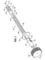
- Figure 1 depicts an applier 10 configurable to apply an expandable medical device 12.
- Applier 10 has an enclosure, or a tube 14 for containing expandable medical device 12 and internal components of applier 10.
- Tube 14 may be created from a moldable plastic, and at least a portion of tube 14 may be translucent or transparent to allow visualization of device 12 or other internal components. Translucency or transparency could also allow light from a light source placed internal to tube 14 to pass externally to tube 14 to illuminate a work area.
- Guide slot 16 is positioned on tube 14 near the proximal end of tube 14.
- Guide slot 16 may have a shape to present stop positions or cam surfaces to the user to guide the user in proper placement of the components of applier 10 during actuation of applier 10.
- the shape of guide slot 16 roughly approximates the letter "Z" and extends about at least a portion of the circumference of tube 14.
- a locator pin 18 moves within guide slot 16 and locates portions of components of applier 10.
- Figure 1 depicts locator pin 18 as a socket-head cap screw; however, locator pin 18 and guide slot 16 may comprise any cam-follower mechanism able to direct movement of components of applier 10.
- Knob 20 extends from the proximal end of applier 10 for control by the user.
- Tube handle 24 attaches to tube 14, also for grasping by the user to manipulate applier 10.
- a cap in the form of bullet nose 22 is placed at the distal end of tube 14.
- Bullet nose 22 protrudes from the distal end of tube 14, and has a distal end shaped to engage and dilate small stoma in tissue. This distal end shape may be conical, but could also be rounded, asymmetrical, pointed, or any shape to facilitate entry into tissue. Bullet nose 22 also possesses on its proximal surface a device taper 70. Device taper 70 is shown substantially conical in shape with the taper facing proximally towards expandable medical device 12 when expandable medical device 12 is loaded within applier 10. Device taper 70 may also take different surface shapes, such as, for example, a convex curved shape, which may facilitate flaring and deployment of expandable medical device 12.
- FIG. 1 further displays the internal mechanism 26 of applier 10 in isometric view.
- Pusher rod 28 extends distally from knob 20 and is hollow for at least a portion of its length to enclose other components.
- Pusher rod slot 30 opens into the internal portions of pusher rod 28 and is elongated to allow differential motion between pusher rod 28 and other components of internal mechanism 26, as will be seen.
- Pusher rod 28 possesses a guide bushing 32 near its proximal end to mate with tube 14 in such a way as to allow longitudinal movement and rotational movement between pusher rod 28 and tube 14.
- Locator pin 18 extends from guide bushing 32.
- a restraint element called device pusher 34
- device pusher 34 is affixed to pusher rod 28 near the distal end of pusher rod 28, and restrains expandable medical device 12 from proximal movement when tube 14 moves proximally.
- device pusher 34 is shown with a substantially flat distal surface, device pusher 34 may alternately possess a tapered distal surface to assist in deploying device 12.
- Bullet nose rod 36 is attached to and extends from bullet nose 22 proximally through pusher rod 28.
- a slip-fit clearance between bullet nose rod 36 and pusher rod 28 allows longitudinal movement between bullet nose rod 36 and pusher rod 28.
- Bullet nose rod slot 38 is cut into bullet nose rod 36 and aligns in operation with pusher rod slot 30.
- Bullet nose rod 36 may take any of several configurations to facilitate manufacture and use.
- bullet nose rod 36 may be integrally molded with bullet nose 22 to become one component.
- bullet nose rod 36 may have a threaded attachment to bullet nose 22 or may itself be composed of two components that are extendable for adjustability.
- a force element embodied by spring 40 connects bullet nose rod 36 to tube handle 24 by engaging bullet nose rod slot 38.
- Spring 40 applies mechanical force urging bullet nose rod 36 and bullet nose 22 proximally. Since tube handle 24 affixes to tube 14, spring 40 applies mechanical force tending to hold bullet nose 22 and tube 14 together, but allowing relative displacement of bullet nose 22 away from tube 14 under a force opposing and greater than the force generated by spring 40.
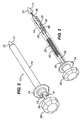
- Figure 2 displays another embodiment of applier 10.
- tube handle 24 attaches at the proximal end of tube 14.
- tube handle 24, rather than tube 14, carries guide slot 16.
- a leg 41 extending from spring 40 fastens to tube handle 24 through a small opening of tube handle 24, and may curve about a portion of tube handle 24 to locate it into position.
- FIG. 3 shows internal mechanism 26 of the embodiment of Figure 2 .
- Tube 14 has been shown in phantom in Figure 3 for clarity, however, tube handle 24 remains to show positional relationships of components.
- Pusher rod 28 extends distally from knob 20 similarly to the embodiment of Figure 2 .
- Device pusher half 35 locates at the distal end of pusher rod 28, affixed to pusher rod 28 by a snap ring 46.
- a second device pusher half 35 omitted for better visibility of associated components, mates with device pusher half 35 to enclose the distal end of pusher rod 28 and to form device pusher 34.
- a cover rod shown as bullet nose rod 36 extending from the cover shown as bullet nose 22, inserts into a distal end of device pusher 34.
- Bullet nose 22 protrudes from the distal end of bullet nose rod 36.
- bullet nose 22 can combine with bullet nose rod 36 into one component, or bullet nose 22 can be a separate component attached to bullet nose rod 36 in a manner to allow an adjustable length between bullet nose 22 and bullet nose rod 36.
- the design can allow length adjustability by, for example, a threaded connection between bullet nose 22 and bullet nose rod 36.
- bullet nose rod slot 38 is cut into the end of bullet nose rod 36.
- An embodiment of locater pin 18 extends radially from the surface of pusher rod 28 near the proximal side of pusher rod 28.
- Tube handle 24 attaches to the proximal end of tube 14.
- Spring 40 hooks to bullet nose rod slot 38 to connect bullet nose rod 36 and tube handle 24.
- Spring 40 applies mechanical force urging bullet nose rod 36 and bullet nose 22 proximally. Since tube handle 24 affixes to tube 14, spring 40 applies mechanical force tending to hold bullet nose 22 and tube 14 together, but allowing relative displacement of bullet nose 22 away from tube 14 under an opposing force greater than that applied by spring 40.
- spring 40 passes through a spring slot 48 created by the mating pusher halves 35.
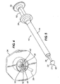
- Figure 4 displays a view of tube handle 24 used in the embodiment of Figure 2 . The view is taken from the distal end of tube handle 24.
- a guide slot 16 of the tube handle 24 shown in Figure 3 is also seen in Figure 4 .
- Guide slot 16 comprises a longitudinal slot 42 following the axis of handle 24 at the proximal side of tube handle 24, opening into a horizontal slot 44 near the distal end of handle 24.
- a pin stop 45 in the embodiment of Figure 4 , is a wall to prevent further distal movement of locator pin 18 without a preliminary rotational movement of pusher rod 28.
- Guide slot 16 has clearance for movement of locator pin 18 through longitudinal slot 42 and through horizontal slot 44, and so allows translation of locator pin 18 and rotation of locator pin 18 about the axis of pusher rod 28 when pusher rod 28 is rotated.
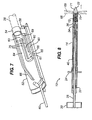
- Figure 5 shows a third embodiment of applier 10.
- applier 10 of Figure 5 carries a tube 14 with attached tube handle 24 at its distal end.
- Pusher rod 28 carries knob 20 at its proximal end and bullet nose 22 at its distal end.
- the embodiment of Figure 5 is shown with an access port 50 open through the entire length of applier 10.
- Other embodiments of applier 10 could have an access port 50 as well.
- Attached to tube 14 at the proximal end of tube 14 is path retainer 52, to direct movements of pusher rod 28, as will be seen.
- Access port 50 may be used for placement of a tool to facilitate surgery.
- a surgeon may place, for example, through access port 50, a tool such as a guide wire to guide applier 10 within the body, a laser or surgical tool to effect further treatment, a fiber optic to give light to the surgical site, a fiber optic with an attached camera to visualize the surgical site, a wire to convey electrical energy, or a tube to convey pneumatic energy.
- Access port 50 may be sealed by, for example, an elastomeric plug when not in use if it becomes necessary to preclude passage of gas for reasons such as, for example, maintenance of pneumoperitenium.
- Figure 6 shows the embodiment of Figure 5 with tube 14 in phantom for clarity.
- pusher rod 28 has knob 20 at its proximal end and bullet nose 22 at its distal end.
- Device pusher 34 attaches near the distal end of pusher rod 28.
- Spring 40 connects to tube 14 through path retainer 52, and to pusher rod 28; however, spring 40 could alternately attach directly to tube 14 or to any component affixed to tube 14. As in previous embodiments, spring 40 applies a force tending to urge bullet nose 22 towards tube 14, so that bullet nose 22 and tube 14 are engaged with a preload but can be deflected apart by a force large enough to overcome the preload.
- Guide clip 54 affixes to pusher rod 28 and engages path retainer 52 in a way to permit relative motion between guide clip 54 and path retainer 52.
- Guide clip 54 although affixed to pusher rod 28, has stationary guide clip leg 58 and deflectable guide clip leg 59 ( Figure 7 ) to slidingly engage portions of path retainer 52.
- Stationary guide clip leg 58 remains substantially fixed relative to pusher rod 28, while deflectable guide clip leg 59 deflects outward, guided by cam surfaces on path retainer 52.
- Figure 7 shows a close view of path retainer 52 used in the embodiment of applier 10 of Figure 5 .
- This view shows the face of path retainer 52 that faces the interior of tube 14.
- the proximal end of spring 40 and positioning guide clip 54 are also shown in Figure 7 .
- Path retainer 52 has a control path 56 to direct and control movement of pusher rod 28 through action of guide clip 54.
- Control path 56 consists of four paths for guidance and control of pusher rod 28. The four paths are flair path 60, return path 62, ejection path 64, and finish path 66. Rails 75 on the surface of path retainer 52 separate the paths.
- a flair stop 61 is at the distal end of return path 62, while clearance slot 63 opens between return path 62 and ejection path 64 near the proximal end of the paths.
- a distal clearance slot 65 opens between flair path 60 and return path 62 near the distal end of the paths.
- Stationary guide clip leg 58 and deflectable guide clip leg 59 are shown preloaded and compressed together by two of rails 75 to ride in flair path 60. In the relaxed state, stationary guide clip 58 and deflectable guide clip leg 59 spread to a distance to encompass the width between finish path 66 and flair path 60.
- control path 56 permits consecutive relaxing and opening of deflectable guide clip leg 59 towards the relaxed, non-preloaded state. Stationary guide clip leg 58 remains within flair path 60, while deflectable guide clip leg 59 moves towards and into finish path 66.
- Each embodiment of applier 10 has an operation sequence, as will be seen.
- the embodiments share commonality in that bullet nose 22 applies force generated by spring 40 to flair expandable medical device 12.
- bullet nose 22 covers the end of tube 14 and is held in position by force applied by spring 40.
- spring 40 deflects to allow bullet nose 22 to lift off of tube 40.
- FIG. 8 depicts the Figure 1 embodiment loaded with a medical device, such as an expandable medical device 12.
- Tube 14 contains expandable medical device 12.
- Expandable medical device 12 can be used to hold two tissue portions together to effect a therapeutic surgical treatment.
- a surgeon can grasp applier 10 and place it into a patient's body.
- the surgeon can, for example, grasp the applier 10 by placing an index and middle finger on tube handle 24 and a thumb on knob 20.
- the surgeon maneuvers any embodiment of applier 10 to a portion of the body near organs needing surgical treatment, such as anastomosis.
- the surgeon may, for example, first divide a section of small intestine as a part of a medical procedure such as a gastric bypass operation. Or, the surgeon may anastomose bowel left behind by removal of a cancerous portion of bowel.
- the surgeon may create an otomy in a section of small intestine and extend applier 10 through the section of small intestine to a position where another otomy is desired.
- the surgeon may then make a second otomy in the wall of the same section and a third otomy in another section of intestine to be anastomosed.
- Applier 10 then can extend through the second and third otomies in the two sections of small intestine.
- the walls carrying the second and third otomies can be shown as proximal tissue portion 68 and distal tissue portion 69. Attaching these tissue portions can create an intestinal anastomosis when the tissue portions are portions of lumens of intestine.
- a surgeon can operate applier 10 to effect a medical procedure such as an anastomosis.
- Tube handle 24 urges tube handle 24 towards knob 20.
- Reactive force placed by the surgeon on knob 20, transfers through pusher rod 28, to device pusher 34, to expandable medical device 12.
- device pusher 34 restrains any proximal movement of expandable medical device 12.
- Spring 40 connected between tube handle 24 and bullet nose rod 36, applies a force tending to pull bullet nose rod 36 in a proximal direction.
- bullet nose rod 36 pulls bullet nose 22 proximally to maintain preloaded contact with tube 14, so that bullet nose 22 travels proximally with tube 14 as one unit relative to device pusher 34.
- Bullet nose rod 36 telescopes into the inner diameter of pusher rod 28.
- device taper 70 contacts expandable medical device 12 to flare it.
- Expandable medical device 12 applies a reactive force to bullet nose 22.
- the distal reactive force overcomes the force applied by spring 40, the reactive force elongates spring 40 and separates bullet nose 22 slightly from tube 14. Flaring expandable medical device 12 begins to emerge from the opening created between tube 14 and bullet nose 22, as shown in Figures 9 and 10 .
- Figures 9 and 10 show flared expandable medical device 12 emerging from applier 10.
- device taper 70 presents a ramp to facilitate the flaring and opening of expandable medical device 12.
- Device taper 70 applies force to an internal portion of expandable medical device 12 to flare expandable medical device 12 and increase the diameter of the distal end of expandable medical device 12.
- the restraint that bullet nose 22 places on expandable medical device 12 prevents expandable medical device 12 from ejecting from tube 14 before expandable medical device 12 is placed into the correct position adjacent to tissue portions requiring surgical treatment.
- the surgeon can use the flared portion of expandable medical device 12, as it is captured by the force exerted by bullet nose 22, to pull distal tissue portion 69 towards proximal tissue portion 68 to effect treatment such as an anastomosis.
- Applier 10 with the extending, flared portion of captured expandable medical device 12 can be utilized as a tool to manipulate tissue.
- Figure 9 shows that the circumferential portion of guide slot 16 moves relatively past locator pin 18.
- distal, axial portion of guide slot 16 aligns with locator pin 18, further movement of tube 14 towards knob 20 is permitted.
- the surgeon is ready to eject expandable medical device 12 from applier 10.
- Figures 11 and 12 show the embodiment of applier 10 shown in Figure 1 with expandable medical device 12 ejected.
- the surgeon continues movement of tube 14 towards knob 20.
- Spring 40 continues to pull bullet nose 22 proximally, while bullet nose rod 36, attached to bullet nose 22, slides freely through pusher rod 28.
- Bullet nose 22 is still preloaded against flared expandable medical device 12, and expandable medical device 12 continues to emerge from the distal end of tube 14.
- the proximal end of bullet nose rod slot 38, where spring 40 attaches reaches the proximal end of pusher rod slot 30, force is now applied by spring 40 to pusher rod 28.
- Spring 40 now extends between pusher rod 28 and tube handle 24.
- Expandable medical device 12 assumes the correct orientation and geometry to perform a useful surgical procedure.
- the relative positions of components of applier 10 after ejection of expandable medical device 12 are shown in Figures 11 and 12 .
- Figures 13 through 17 depict the operation of the embodiment of applier 10 shown in Figure 2 .
- Figure 13 shows the embodiment of applier 10 loaded with expandable medical device 12.
- the surgeon urges tube handle 24 towards knob 20.
- Reactive force placed by the surgeon on knob 20 transfers through pusher rod 28, snap ring 46, and device pusher 34 to expandable medical device 12.
- device pusher 34 restrains any rearward movement of expandable medical device 12.
- force applied by spring 40 connected between tube handle 24 and bullet nose rod 36, urges bullet nose rod 36 proximally through device pusher 34.
- Bullet nose rod 36 pulls bullet nose 22 proximally to maintain preloaded contact with tube 14, so that tube 14 and bullet nose 22 proceed proximally as one unit.
- device taper 70 contacts expandable medical device 12 to flare it.
- Expandable medical device 12 applies a reactive force to bullet nose 22 greater than that applied by spring 40 to elongate spring 40 and separate bullet nose 22 slightly from tube 14. Flaring expandable medical device 12 begins to emerge from the opening created between tube 14 and bullet nose 22, as shown in Figure 14 and 15 .
- Figure 15 shows in section view flared expandable medical device 12 emerging from the embodiment of applier 10. Because spring 40 continues to urge bullet nose 22 proximally towards tube 14, device taper 70 presents a ramp to facilitate the flaring and opening of expandable medical device 12. In addition, the restraint that bullet nose 22 places on expandable medical device 12 prevents expandable medical device 12 from ejecting from tube 14 before expandable medical device 12 is placed into the correct position adjacent to tissue portions to be surgically treated. The surgeon can use the flared portion of expandable medical device 12, as it is captured by the force exerted by bullet nose 22, to pull a distal tissue portion 69 towards a proximal tissue portion 68 to effect treatment such as an anastomosis. Applier 10 with the extending, flared portion of captured expandable medical device 12 can be utilized as a tool to manipulate tissue during a surgical procedure.
- Figure 16 and 17 show cross-sectional views of expandable medical device 12 ejected from applier 10 and engaging proximal tissue portion 68 to distal tissue portion 69.
- the surgeon continues movement of tube 14 towards knob 20.
- Spring 40 continues to pull bullet nose 22 proximally, while bullet nose rod 36, attached to bullet nose 22, slides freely through device pusher 34.
- Bullet nose 22 is still preloaded against flared expandable medical device 12 by force exerted by spring 40.
- force is now applied to pusher rod 28.
- Bullet nose 22 can no longer follow tube 14 proximally, and is no longer preloaded to tube 14.
- tube 14 Further proximal motion of tube 14 relative to pusher rod 28 extends spring 40. There is no longer relative motion between bullet nose 22 and device pusher 34. Tube 14, however, moves relative to bullet nose 22 and device pusher 24. The space between device pusher 34 and bullet nose 22, containing expandable medical device 12, emerges from tube 14 to eject expandable medical device 12 as tube 14 is pulled proximally.
- Figures 18 through 23 demonstrate the operation of the embodiment of applier 10 shown in Figure 5 .
- Figure 18 shows the Figure 5 embodiment of applier 10 in the loaded position with expandable medical device 12 placed within tube 14.
- Force applied by spring 40 holds bullet nose 22 against the distal end of tube 14.
- a surgeon moves tube 14 proximally towards knob 20 against the force of spring 40 by grasping tube handle 24 as in previous embodiments.
- Tube 14 moves proximally relative to pusher rod 28 and device pusher 34.
- Device pusher 34 restrains proximal movement of expandable medical device 12.
- a gap opens between tube 14 and bullet nose 22. Expandable medical device 12 begins to emerge from the distal end of tube 14.
- Figure 19 also shows an isometric view of path retainer 52 and guide clip 54.
- Path retainer 52 is attached to tube 14 and moves proximally with guide clip 54.
- control path 56 moves relative to guide clip 54 to control movements of tube 14.
- flair path 60 moves past stationary guide clip leg 58 and deflectable guide clip leg 59 until flair stop 61 abuts guide clip 54.
- Flair stop 61 prevents further proximal motion of tube 14.
- flair stop 61 abuts guide clip 54
- the deflectable guide clip leg 59 will move through distal clearance slot 65 to return path 62.
- Applier 10 now takes the position shown in Figure 20 , with expandable medical device 12 emerging from the distal end of tube 14. Releasing force from tube 14 will allow spring 40 to move tube 14 distally into the position shown in Figure 21 .
- Figure 21 shows a sectional view of the embodiment of applier 10 of Figure 6 with expandable medical device 12 flared from the distal end of tube 14.
- spring 40 pulls tube 14 distally towards bullet nose 22.
- Device taper 70 contacts expandable medical device 12 to assist in flaring expandable medical device 12. Force from spring 40 is applied to device 12.
- This embodiment of applier 10 in the configuration of Figure 21 may be used to capture distal tissue wall 69 to approximate it to a proximal tissue wall to perform a surgical procedure such as an anastomosis.
- a surgeon can use applier 10 with the flared expandable medical device 12 as a tool to manipulate tissue.
- Figure 22 shows path retainer 52 and guide clip 54 as applier 10 is in the flared position of Figure 21 .
- Path retainer 52 has moved to the initial position relative to guide clip 54 while deflectable guide clip leg 59 was within return path 62.
- Deflectable guide clip leg 59 then moved through clearance slot 63 to ejection path 64 when path retainer 52 reached the initial position with guide clip 54 at its proximal end.
- Figure 23 shows expandable medical device 12 ejected by applier 10. After expandable medical device 12 has been placed into position, the surgeon may now eject device 12 by pulling tube handle 24 towards knob 20 to again urge tube 14 proximally relative to pusher rod 28. When device pusher 34 contacts the proximal end of expandable medical device 12, expandable medical device 12 is prevented from further proximal movement. Tube 14 moves proximally from expandable medical device 12 to deploy it.
- Figure 24 depicts the action of path retainer 52 moving proximally past guide clip 54 while applier 10 deploys expandable medical device 12.
- Ejection path 64 moves proximally past deflectable guide clip leg 59.
- tube 14 can move further proximally to a position allowing device pusher 34 to completely eject expandable medical device 12.
- the curve of guide rail 75 adjacent to ejection path 64 places a side force on deflectable guide clip leg 59, moving it closer to stationary guide clip leg 58.
- the force generated by moving deflectable guide clip leg 59 can give tactile feedback to the surgeon that tube 14 is approaching the end of its allowable proximal movement.
- movement of portions of applier 10 describe relative movement of the elements with respect to each other.
- movement of tube 14 proximally towards knob 20 can also be described as movement of knob 20 distally towards tube 14.
- movement of tube 14 proximally past device pusher 34 could also be described as distal movement of device pusher 34 within a stationary tube 14.
- expandable medical device 12 is described as restrained from proximal movement by device pusher 34 when tube 14 moves proximally past. Changing the stationary element from device pusher 34 to tube 14 changes the description to one of expandable medical device 12 urged distally by distally advancing device pusher 34.
- tube 14 could become a flexible tube, and the mechanisms within applier 10 may become flexible to maneuver through a long lumen, such as a section of small bowel, to effect an anastomosis through a long, flexible lumen.
- a long, flexible tube may be used laproscopically or endoscopically.
- applier 10 could have a long, rigid, curved tube, or a long, rigid, straight tube, and applier 10 could be placed through an obturator port and used laproscopically or endoscopically. Length and curvature becomes advantageous in endoscopic or laproscopic surgery, especially when performing a surgical procedure on a bariatric patient. In either a rigid or a flexible form of an applier 10, restriction of gas flow through the instrument becomes advantageous when maintenance of a pneumoperiteneum is desired as in, for example, endoscopic surgery.
- applier 10 may have a geometry small enough to be conveniently placed through the opening of a hand port used for hand-assisted laproscopic surgery, such as, for example, the Lap-Disk ® hand port sold by Ethicon Endo-Surgery in Cincinnati, Ohio.
- a surgeon using applier 10 through a hand port may use an endoscope through a secondary port for visualization, and may also maintain a pneumoperiteneum.
- the surgeon may also make use of trocars, graspers, cutters, and other endoscopic instruments inserted through auxiliary ports to assist in grasping lumens or creating otomies in lumens to perform surgical procedures such as anastomosis.
- a long, rigid version of applier 10, or a long, flexible embodiment of applier 10 may be used through an auxiliary port while tissue is manipulated by the surgeon using a hand placed through a hand port.
- the surface of distal taper 71 on bullet nose 22 may take many forms advantageous for various types of tissue manipulation, as illustrated in Figures 25A through 25F.
- Figure 25A represents a conical tipped nose that is blunted for low tissue trauma and for good visibility past the distal end.
- Figure 25B depicts a nose that is fluted to allow torque to be applied to tissue.
- Figure 25B depicts four flutes, although three or any other number of flutes may suffice.
- Figure 25C depicts a nose having a convex curve for rapid dilation of an otomy in a short space, while Figure 25D shows a nose having a concave surface for gentle dilation of friable tissue.
- An offset swept nose shown in Figure 25E , may be used because of its asymmetry for better visibility to one side and may be used to assist in manipulation by using its asymmetry to minimally grasp tissue.
- Figure 25F shows a spherical nose to produce a short length for operation in limited space and to reduce the chance of tissue trauma. Combinations of these surfaces may also be advantageous, for example, a nose having a concave surface as depicted in Figure 25D may also posses flutes as depicted in Figure 25B . Other combinations may occur to one skilled in the art.
Applications Claiming Priority (2)
| Application Number | Priority Date | Filing Date | Title |
|---|---|---|---|
| US50779903P | 2003-09-30 | 2003-09-30 | |
| US507799P | 2003-09-30 |
Publications (2)
| Publication Number | Publication Date |
|---|---|
| EP1520526A1 EP1520526A1 (en) | 2005-04-06 |
| EP1520526B1 true EP1520526B1 (en) | 2008-11-05 |
Family
ID=34312480
Family Applications (1)
| Application Number | Title | Priority Date | Filing Date |
|---|---|---|---|
| EP04256009A Not-in-force EP1520526B1 (en) | 2003-09-30 | 2004-09-29 | Applier for a surgical device |
Country Status (9)
| Country | Link |
|---|---|
| EP (1) | EP1520526B1 (pt) |
| JP (1) | JP4841821B2 (pt) |
| CN (1) | CN1654021A (pt) |
| AT (1) | ATE413140T1 (pt) |
| AU (2) | AU2004216615A1 (pt) |
| BR (1) | BRPI0406034B1 (pt) |
| CA (1) | CA2482697C (pt) |
| DE (1) | DE602004017555D1 (pt) |
| MX (1) | MXPA04009619A (pt) |
Families Citing this family (16)
| Publication number | Priority date | Publication date | Assignee | Title |
|---|---|---|---|---|
| US8425539B2 (en) | 2004-04-12 | 2013-04-23 | Xlumena, Inc. | Luminal structure anchoring devices and methods |
| EP1858396B1 (en) | 2004-12-08 | 2019-02-06 | Boston Scientific Scimed, Inc. | Apparatus for performing needle guided interventions |
| US7547311B2 (en) | 2005-05-03 | 2009-06-16 | Ethicon Endo-Surgery, Inc. | Spring-based firing mechanism for anastomotic ring applier |
| US7691113B2 (en) * | 2005-05-05 | 2010-04-06 | Ethicon Endo-Surgery, Inc. | Screw tip control for anastomotic ring applier |
| US8777967B2 (en) | 2005-06-09 | 2014-07-15 | Xlumena, Inc. | Methods and devices for anchoring to tissue |
| US8784437B2 (en) | 2005-06-09 | 2014-07-22 | Xlumena, Inc. | Methods and devices for endosonography-guided fundoplexy |
| US8454632B2 (en) | 2008-05-12 | 2013-06-04 | Xlumena, Inc. | Tissue anchor for securing tissue layers |
| US8357193B2 (en) | 2009-05-29 | 2013-01-22 | Xlumena, Inc. | Apparatus and method for deploying stent across adjacent tissue layers |
| US9364259B2 (en) | 2009-04-21 | 2016-06-14 | Xlumena, Inc. | System and method for delivering expanding trocar through a sheath |
| EP2854654B1 (en) | 2012-05-17 | 2019-11-06 | Boston Scientific Scimed, Inc. | Devices for access across adjacent tissue layers |
| CN105658182B (zh) | 2013-02-21 | 2018-07-27 | 波士顿科学国际有限公司 | 用于形成吻合口的装置和方法 |
| KR101514055B1 (ko) * | 2013-12-17 | 2015-04-21 | 주식회사 스텐다드싸이텍 | 스텐트 삽입장치 |
| CN107106254A (zh) * | 2014-11-06 | 2017-08-29 | Devicor医疗产业收购公司 | 弹簧弹出的活检标记物 |
| CN106821444B (zh) * | 2016-12-22 | 2023-06-27 | 杨西群 | 用于钛镍基形状记忆合金组织闭合夹的装夹器和放送装置 |
| KR102244846B1 (ko) * | 2019-04-18 | 2021-04-28 | 주식회사 엠아이텍 | 스텐트 딜리버리 장치 |
| CN112998810B (zh) * | 2021-04-06 | 2022-11-25 | 张儒麟 | 一种腱鞘囊肿治疗装置 |
Family Cites Families (13)
| Publication number | Priority date | Publication date | Assignee | Title |
|---|---|---|---|---|
| FR2245324A1 (en) * | 1973-09-12 | 1975-04-25 | Prioton Bernard | Process and device for portal disconnection of the oesophagus - clip is inserted with remote-controlled applicator |
| US5478353A (en) * | 1987-05-14 | 1995-12-26 | Yoon; Inbae | Suture tie device system and method for suturing anatomical tissue proximate an opening |
| US5797920A (en) * | 1996-06-14 | 1998-08-25 | Beth Israel Deaconess Medical Center | Catheter apparatus and method using a shape-memory alloy cuff for creating a bypass graft in-vivo |
| ATE320229T1 (de) * | 1998-01-30 | 2006-04-15 | St Jude Medical Atg Inc | Medizinischer transplantatverbinder oder stopfen sowie verfahren zu ihrer herstellung |
| JP2002534208A (ja) * | 1999-01-15 | 2002-10-15 | ベントリカ, インコーポレイテッド | 血管吻合を形成するための方法およびデバイス |
| EP1180976A1 (en) * | 1999-05-03 | 2002-02-27 | Ventrica Inc. | Methods and devices for placing a conduit in fluid communication with a target vessel |
| US6287329B1 (en) * | 1999-06-28 | 2001-09-11 | Nitinol Development Corporation | Stent keeper for a self-expanding stent delivery system |
| ATE284184T1 (de) * | 2000-01-31 | 2004-12-15 | Advanced Cardiovascular System | Selbstexpandierender stent mit erhöhter zuführgenauigkeit |
| US6602280B2 (en) * | 2000-02-02 | 2003-08-05 | Trivascular, Inc. | Delivery system and method for expandable intracorporeal device |
| US6702843B1 (en) * | 2000-04-12 | 2004-03-09 | Scimed Life Systems, Inc. | Stent delivery means with balloon retraction means |
| US7115136B2 (en) * | 2001-06-20 | 2006-10-03 | Park Medical Llc | Anastomotic device |
| CA2450959C (en) * | 2001-06-20 | 2011-01-04 | Park Medical, Llc | Anastomotic device |
| US7637919B2 (en) * | 2002-01-30 | 2009-12-29 | Olympus Corporation | Anastomosis system for performing anastomosis in body |
-
2004
- 2004-09-28 CA CA2482697A patent/CA2482697C/en not_active Expired - Fee Related
- 2004-09-29 EP EP04256009A patent/EP1520526B1/en not_active Not-in-force
- 2004-09-29 AU AU2004216615A patent/AU2004216615A1/en not_active Abandoned
- 2004-09-29 DE DE602004017555T patent/DE602004017555D1/de active Active
- 2004-09-29 JP JP2004284902A patent/JP4841821B2/ja not_active Expired - Fee Related
- 2004-09-29 AT AT04256009T patent/ATE413140T1/de not_active IP Right Cessation
- 2004-09-30 CN CN200410103361.5A patent/CN1654021A/zh active Pending
- 2004-09-30 BR BRPI0406034-2A patent/BRPI0406034B1/pt not_active IP Right Cessation
- 2004-09-30 MX MXPA04009619A patent/MXPA04009619A/es active IP Right Grant
-
2011
- 2011-05-24 AU AU2011202410A patent/AU2011202410A1/en not_active Abandoned
Also Published As
| Publication number | Publication date |
|---|---|
| MXPA04009619A (es) | 2005-06-08 |
| CA2482697C (en) | 2012-11-20 |
| CN1654021A (zh) | 2005-08-17 |
| BRPI0406034A (pt) | 2005-06-14 |
| JP4841821B2 (ja) | 2011-12-21 |
| JP2005103277A (ja) | 2005-04-21 |
| ATE413140T1 (de) | 2008-11-15 |
| EP1520526A1 (en) | 2005-04-06 |
| AU2004216615A1 (en) | 2005-04-14 |
| BRPI0406034B1 (pt) | 2014-01-28 |
| AU2011202410A1 (en) | 2011-06-09 |
| CA2482697A1 (en) | 2005-03-30 |
| DE602004017555D1 (de) | 2008-12-18 |
Similar Documents
| Publication | Publication Date | Title |
|---|---|---|
| AU2011202410A1 (en) | Applier for a surgical device | |
| US20050075656A1 (en) | Applier for a surgical device | |
| US10702254B2 (en) | Surgical device and accessories | |
| US5450842A (en) | Endoscopic surgical retractor | |
| US8770460B2 (en) | Shield for surgical stapler and method of use | |
| US20050075655A1 (en) | Applier having automated release of surgical device | |
| AU2011202408B2 (en) | Applier having automated release of surgical device | |
| EP3461443B1 (en) | Uterine manipulator with adjustable cervical cup | |
| CA2521344C (en) | Applier having automated release of surgical device | |
| JP2005103277A5 (pt) | ||
| CA2520688C (en) | Applier for a surgical device | |
| US20220202433A1 (en) | Control mechanism for end effectors and method of use | |
| WO2011087848A1 (en) | Shield for surgical stapler and method of use |
Legal Events
| Date | Code | Title | Description |
|---|---|---|---|
| PUAI | Public reference made under article 153(3) epc to a published international application that has entered the european phase |
Free format text: ORIGINAL CODE: 0009012 |
|
| AK | Designated contracting states |
Kind code of ref document: A1 Designated state(s): AT BE BG CH CY CZ DE DK EE ES FI FR GB GR HU IE IT LI LU MC NL PL PT RO SE SI SK TR |
|
| AX | Request for extension of the european patent |
Extension state: AL HR LT LV MK |
|
| 17P | Request for examination filed |
Effective date: 20050915 |
|
| AKX | Designation fees paid |
Designated state(s): AT BE BG CH CY CZ DE DK EE ES FI FR GB GR HU IE IT LI LU MC NL PL PT RO SE SI SK TR |
|
| GRAP | Despatch of communication of intention to grant a patent |
Free format text: ORIGINAL CODE: EPIDOSNIGR1 |
|
| GRAS | Grant fee paid |
Free format text: ORIGINAL CODE: EPIDOSNIGR3 |
|
| GRAA | (expected) grant |
Free format text: ORIGINAL CODE: 0009210 |
|
| AK | Designated contracting states |
Kind code of ref document: B1 Designated state(s): AT BE BG CH CY CZ DE DK EE ES FI FR GB GR HU IE IT LI LU MC NL PL PT RO SE SI SK TR |
|
| REG | Reference to a national code |
Ref country code: GB Ref legal event code: FG4D |
|
| REG | Reference to a national code |
Ref country code: CH Ref legal event code: EP |
|
| REG | Reference to a national code |
Ref country code: IE Ref legal event code: FG4D |
|
| REF | Corresponds to: |
Ref document number: 602004017555 Country of ref document: DE Date of ref document: 20081218 Kind code of ref document: P |
|
| NLV1 | Nl: lapsed or annulled due to failure to fulfill the requirements of art. 29p and 29m of the patents act | ||
| PG25 | Lapsed in a contracting state [announced via postgrant information from national office to epo] |
Ref country code: ES Free format text: LAPSE BECAUSE OF FAILURE TO SUBMIT A TRANSLATION OF THE DESCRIPTION OR TO PAY THE FEE WITHIN THE PRESCRIBED TIME-LIMIT Effective date: 20090216 Ref country code: AT Free format text: LAPSE BECAUSE OF FAILURE TO SUBMIT A TRANSLATION OF THE DESCRIPTION OR TO PAY THE FEE WITHIN THE PRESCRIBED TIME-LIMIT Effective date: 20081105 |
|
| PG25 | Lapsed in a contracting state [announced via postgrant information from national office to epo] |
Ref country code: SI Free format text: LAPSE BECAUSE OF FAILURE TO SUBMIT A TRANSLATION OF THE DESCRIPTION OR TO PAY THE FEE WITHIN THE PRESCRIBED TIME-LIMIT Effective date: 20081105 Ref country code: FI Free format text: LAPSE BECAUSE OF FAILURE TO SUBMIT A TRANSLATION OF THE DESCRIPTION OR TO PAY THE FEE WITHIN THE PRESCRIBED TIME-LIMIT Effective date: 20081105 Ref country code: PL Free format text: LAPSE BECAUSE OF FAILURE TO SUBMIT A TRANSLATION OF THE DESCRIPTION OR TO PAY THE FEE WITHIN THE PRESCRIBED TIME-LIMIT Effective date: 20081105 Ref country code: NL Free format text: LAPSE BECAUSE OF FAILURE TO SUBMIT A TRANSLATION OF THE DESCRIPTION OR TO PAY THE FEE WITHIN THE PRESCRIBED TIME-LIMIT Effective date: 20081105 |
|
| PG25 | Lapsed in a contracting state [announced via postgrant information from national office to epo] |
Ref country code: BG Free format text: LAPSE BECAUSE OF FAILURE TO SUBMIT A TRANSLATION OF THE DESCRIPTION OR TO PAY THE FEE WITHIN THE PRESCRIBED TIME-LIMIT Effective date: 20090205 Ref country code: BE Free format text: LAPSE BECAUSE OF FAILURE TO SUBMIT A TRANSLATION OF THE DESCRIPTION OR TO PAY THE FEE WITHIN THE PRESCRIBED TIME-LIMIT Effective date: 20081105 Ref country code: EE Free format text: LAPSE BECAUSE OF FAILURE TO SUBMIT A TRANSLATION OF THE DESCRIPTION OR TO PAY THE FEE WITHIN THE PRESCRIBED TIME-LIMIT Effective date: 20081105 Ref country code: DK Free format text: LAPSE BECAUSE OF FAILURE TO SUBMIT A TRANSLATION OF THE DESCRIPTION OR TO PAY THE FEE WITHIN THE PRESCRIBED TIME-LIMIT Effective date: 20081105 Ref country code: RO Free format text: LAPSE BECAUSE OF FAILURE TO SUBMIT A TRANSLATION OF THE DESCRIPTION OR TO PAY THE FEE WITHIN THE PRESCRIBED TIME-LIMIT Effective date: 20081105 |
|
| PG25 | Lapsed in a contracting state [announced via postgrant information from national office to epo] |
Ref country code: SE Free format text: LAPSE BECAUSE OF FAILURE TO SUBMIT A TRANSLATION OF THE DESCRIPTION OR TO PAY THE FEE WITHIN THE PRESCRIBED TIME-LIMIT Effective date: 20090205 Ref country code: PT Free format text: LAPSE BECAUSE OF FAILURE TO SUBMIT A TRANSLATION OF THE DESCRIPTION OR TO PAY THE FEE WITHIN THE PRESCRIBED TIME-LIMIT Effective date: 20090406 Ref country code: CZ Free format text: LAPSE BECAUSE OF FAILURE TO SUBMIT A TRANSLATION OF THE DESCRIPTION OR TO PAY THE FEE WITHIN THE PRESCRIBED TIME-LIMIT Effective date: 20081105 |
|
| PLBE | No opposition filed within time limit |
Free format text: ORIGINAL CODE: 0009261 |
|
| STAA | Information on the status of an ep patent application or granted ep patent |
Free format text: STATUS: NO OPPOSITION FILED WITHIN TIME LIMIT |
|
| PG25 | Lapsed in a contracting state [announced via postgrant information from national office to epo] |
Ref country code: SK Free format text: LAPSE BECAUSE OF FAILURE TO SUBMIT A TRANSLATION OF THE DESCRIPTION OR TO PAY THE FEE WITHIN THE PRESCRIBED TIME-LIMIT Effective date: 20081105 |
|
| 26N | No opposition filed |
Effective date: 20090806 |
|
| PG25 | Lapsed in a contracting state [announced via postgrant information from national office to epo] |
Ref country code: MC Free format text: LAPSE BECAUSE OF NON-PAYMENT OF DUE FEES Effective date: 20090930 |
|
| REG | Reference to a national code |
Ref country code: CH Ref legal event code: PL |
|
| REG | Reference to a national code |
Ref country code: IE Ref legal event code: MM4A |
|
| PG25 | Lapsed in a contracting state [announced via postgrant information from national office to epo] |
Ref country code: IE Free format text: LAPSE BECAUSE OF NON-PAYMENT OF DUE FEES Effective date: 20090929 |
|
| PG25 | Lapsed in a contracting state [announced via postgrant information from national office to epo] |
Ref country code: LI Free format text: LAPSE BECAUSE OF NON-PAYMENT OF DUE FEES Effective date: 20090930 Ref country code: CH Free format text: LAPSE BECAUSE OF NON-PAYMENT OF DUE FEES Effective date: 20090930 Ref country code: GR Free format text: LAPSE BECAUSE OF FAILURE TO SUBMIT A TRANSLATION OF THE DESCRIPTION OR TO PAY THE FEE WITHIN THE PRESCRIBED TIME-LIMIT Effective date: 20090206 |
|
| PG25 | Lapsed in a contracting state [announced via postgrant information from national office to epo] |
Ref country code: LU Free format text: LAPSE BECAUSE OF NON-PAYMENT OF DUE FEES Effective date: 20090929 |
|
| PG25 | Lapsed in a contracting state [announced via postgrant information from national office to epo] |
Ref country code: HU Free format text: LAPSE BECAUSE OF FAILURE TO SUBMIT A TRANSLATION OF THE DESCRIPTION OR TO PAY THE FEE WITHIN THE PRESCRIBED TIME-LIMIT Effective date: 20090506 |
|
| PG25 | Lapsed in a contracting state [announced via postgrant information from national office to epo] |
Ref country code: TR Free format text: LAPSE BECAUSE OF FAILURE TO SUBMIT A TRANSLATION OF THE DESCRIPTION OR TO PAY THE FEE WITHIN THE PRESCRIBED TIME-LIMIT Effective date: 20081105 |
|
| PG25 | Lapsed in a contracting state [announced via postgrant information from national office to epo] |
Ref country code: CY Free format text: LAPSE BECAUSE OF FAILURE TO SUBMIT A TRANSLATION OF THE DESCRIPTION OR TO PAY THE FEE WITHIN THE PRESCRIBED TIME-LIMIT Effective date: 20081105 |
|
| REG | Reference to a national code |
Ref country code: FR Ref legal event code: PLFP Year of fee payment: 13 |
|
| REG | Reference to a national code |
Ref country code: FR Ref legal event code: PLFP Year of fee payment: 14 |
|
| REG | Reference to a national code |
Ref country code: FR Ref legal event code: PLFP Year of fee payment: 15 |
|
| PGFP | Annual fee paid to national office [announced via postgrant information from national office to epo] |
Ref country code: FR Payment date: 20190815 Year of fee payment: 16 Ref country code: IT Payment date: 20190917 Year of fee payment: 16 |
|
| PGFP | Annual fee paid to national office [announced via postgrant information from national office to epo] |
Ref country code: GB Payment date: 20190926 Year of fee payment: 16 |
|
| REG | Reference to a national code |
Ref country code: DE Ref legal event code: R119 Ref document number: 602004017555 Country of ref document: DE |
|
| PG25 | Lapsed in a contracting state [announced via postgrant information from national office to epo] |
Ref country code: DE Free format text: LAPSE BECAUSE OF NON-PAYMENT OF DUE FEES Effective date: 20200401 |
|
| GBPC | Gb: european patent ceased through non-payment of renewal fee |
Effective date: 20200929 |
|
| PG25 | Lapsed in a contracting state [announced via postgrant information from national office to epo] |
Ref country code: FR Free format text: LAPSE BECAUSE OF NON-PAYMENT OF DUE FEES Effective date: 20200930 |
|
| PG25 | Lapsed in a contracting state [announced via postgrant information from national office to epo] |
Ref country code: GB Free format text: LAPSE BECAUSE OF NON-PAYMENT OF DUE FEES Effective date: 20200929 |
|
| PG25 | Lapsed in a contracting state [announced via postgrant information from national office to epo] |
Ref country code: IT Free format text: LAPSE BECAUSE OF NON-PAYMENT OF DUE FEES Effective date: 20200929 |