EP1520105B1 - Method for detecting the state of charge of an electromagnetic pump having a vibrating core and pertaining to an electrical household appliance - Google Patents
Method for detecting the state of charge of an electromagnetic pump having a vibrating core and pertaining to an electrical household appliance Download PDFInfo
- Publication number
- EP1520105B1 EP1520105B1 EP04742421A EP04742421A EP1520105B1 EP 1520105 B1 EP1520105 B1 EP 1520105B1 EP 04742421 A EP04742421 A EP 04742421A EP 04742421 A EP04742421 A EP 04742421A EP 1520105 B1 EP1520105 B1 EP 1520105B1
- Authority
- EP
- European Patent Office
- Prior art keywords
- pump
- instant
- state
- detecting
- loading
- Prior art date
- Legal status (The legal status is an assumption and is not a legal conclusion. Google has not performed a legal analysis and makes no representation as to the accuracy of the status listed.)
- Expired - Lifetime
Links
- 238000000034 method Methods 0.000 title claims abstract description 25
- XLYOFNOQVPJJNP-UHFFFAOYSA-N water Substances O XLYOFNOQVPJJNP-UHFFFAOYSA-N 0.000 claims description 14
- 238000013459 approach Methods 0.000 abstract description 2
- 238000001514 detection method Methods 0.000 description 5
- XEEYBQQBJWHFJM-UHFFFAOYSA-N Iron Chemical compound [Fe] XEEYBQQBJWHFJM-UHFFFAOYSA-N 0.000 description 4
- 229910052742 iron Inorganic materials 0.000 description 2
- 230000002159 abnormal effect Effects 0.000 description 1
- 239000003990 capacitor Substances 0.000 description 1
- 238000010586 diagram Methods 0.000 description 1
- 238000006073 displacement reaction Methods 0.000 description 1
- 230000000694 effects Effects 0.000 description 1
- 238000002474 experimental method Methods 0.000 description 1
- 235000000396 iron Nutrition 0.000 description 1
- 238000002955 isolation Methods 0.000 description 1
- 239000002184 metal Substances 0.000 description 1
- 229910052751 metal Inorganic materials 0.000 description 1
- 238000012986 modification Methods 0.000 description 1
- 230000004048 modification Effects 0.000 description 1
- 230000003534 oscillatory effect Effects 0.000 description 1
- 230000000737 periodic effect Effects 0.000 description 1
- 238000007493 shaping process Methods 0.000 description 1
- 238000006467 substitution reaction Methods 0.000 description 1
- 230000001960 triggered effect Effects 0.000 description 1
Images
Classifications
-
- F—MECHANICAL ENGINEERING; LIGHTING; HEATING; WEAPONS; BLASTING
- F04—POSITIVE - DISPLACEMENT MACHINES FOR LIQUIDS; PUMPS FOR LIQUIDS OR ELASTIC FLUIDS
- F04B—POSITIVE-DISPLACEMENT MACHINES FOR LIQUIDS; PUMPS
- F04B49/00—Control, e.g. of pump delivery, or pump pressure of, or safety measures for, machines, pumps, or pumping installations, not otherwise provided for, or of interest apart from, groups F04B1/00 - F04B47/00
- F04B49/06—Control using electricity
- F04B49/065—Control using electricity and making use of computers
-
- F—MECHANICAL ENGINEERING; LIGHTING; HEATING; WEAPONS; BLASTING
- F04—POSITIVE - DISPLACEMENT MACHINES FOR LIQUIDS; PUMPS FOR LIQUIDS OR ELASTIC FLUIDS
- F04B—POSITIVE-DISPLACEMENT MACHINES FOR LIQUIDS; PUMPS
- F04B17/00—Pumps characterised by combination with, or adaptation to, specific driving engines or motors
- F04B17/03—Pumps characterised by combination with, or adaptation to, specific driving engines or motors driven by electric motors
- F04B17/04—Pumps characterised by combination with, or adaptation to, specific driving engines or motors driven by electric motors using solenoids
- F04B17/046—Pumps characterised by combination with, or adaptation to, specific driving engines or motors driven by electric motors using solenoids the fluid flowing through the moving part of the motor
-
- F—MECHANICAL ENGINEERING; LIGHTING; HEATING; WEAPONS; BLASTING
- F04—POSITIVE - DISPLACEMENT MACHINES FOR LIQUIDS; PUMPS FOR LIQUIDS OR ELASTIC FLUIDS
- F04B—POSITIVE-DISPLACEMENT MACHINES FOR LIQUIDS; PUMPS
- F04B2203/00—Motor parameters
- F04B2203/04—Motor parameters of linear electric motors
- F04B2203/0401—Current
-
- F—MECHANICAL ENGINEERING; LIGHTING; HEATING; WEAPONS; BLASTING
- F04—POSITIVE - DISPLACEMENT MACHINES FOR LIQUIDS; PUMPS FOR LIQUIDS OR ELASTIC FLUIDS
- F04B—POSITIVE-DISPLACEMENT MACHINES FOR LIQUIDS; PUMPS
- F04B2203/00—Motor parameters
- F04B2203/04—Motor parameters of linear electric motors
- F04B2203/0402—Voltage
Definitions
- the present invention relates to a method and a device for detecting the state of charge, and in particular the idling operation, of a vibrating core electromagnetic pump for equipping an electrical household appliance.
- the invention also relates to an electrical household appliance comprising such a detection device.
- an object of the present invention is to remedy these disadvantages by proposing a method and a device for detecting the state of charge of a vibrating core electromagnetic pump which is simple and economical to produce.
- the subject of the invention is a method for detecting the state of charge of an electromagnetic pump with a vibrating core equipping an electrical household appliance, the pump being powered by a rectified mono-alternating voltage U P , characterized in that, on each power supply period of the pump, the state of charge of the pump is detected by measuring the time ⁇ T between the instant t 0 where the pump current I P reaches its maximum of a reference time t ref power cycle of the pump.
- the invention also relates to a device for detecting the state of charge of a vibrating core electromagnetic pump powered by a rectified single-phase voltage using the method described above, characterized in that it comprises means for detecting the instant t 0 where the pump current I P reaches its maximum.
- the invention also relates to an electrical appliance provided with a electromagnetic pump with a vibrating core fed by a reservoir and comprising such a device for detecting the state of charge.
- said state of charge detection device is used to determine the empty operation of the pump and alert the user to the need to fill the water tank with water. the pump.
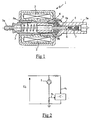
- FIG. 1 schematically represents an example of an electromagnetic pump 1 with a vibrating core conventionally used on an electrical appliance of the steam iron type.
- the pump is supplied with water by a reservoir not shown in the figure.
- the pump 1 comprises a coil 2 surrounding a metal hollow core 4 slidably mounted in the axial direction inside a tubular element 3.
- the core 4 comprises a piston end 4a which is guided by a second tubular element 5 provided with two non-return valves 6 and 7.
- the magnetic field created by the coil 2 causes the displacement of the core 4 against a return spring 9a, the movement of the core 4 under the effect of the spring 9a being damped at the end of the stroke by a second spring 9b and by a resilient abutment 8.
- the pump is supplied with water by the end 3a of the tubular element 3 and the water is expelled under pressure through the orifice 5a of the tubular element 5.
- the electromagnetic pump 1 is powered by a voltage U P rectified mono alternating so that the core 4 moves back and forth during the periodic supply of the coil 2.
- the voltage Up feed illustrated in Figure 3 , is advantageously obtained by simple rectification, by means of a diode, of the AC voltage U S available on the mains.
- FIG. 2 schematically illustrates the power supply of the pump 1 provided with a state of charge detection device according to the invention.
- the pump 1 is connected to the supply voltage U P by being connected in series with a resistor.
- a microcontroller C having an analog digital converter input e 1 for measuring the pump current I P and an input 2 for synchronizing the mains voltage is connected to the supply circuit of the pump.
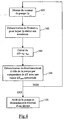
- the microcontroller C measures at each instant the pump current I P and determines, during a second step 102, the instant t 0 of the supply period of the pump for which the current I P is maximum.
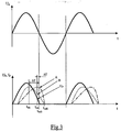
- the microcontroller C measures the time ⁇ T elapsed between the time t 0 previously detected and a reference time t ref of the pump supply cycle.
- This reference instant t ref is, for example, the instant t ref1 of the curve U P , represented in solid line in FIG. 4, where the Supply voltage Up of the pump becomes zero.
- the reference instant t ref may also correspond to the instant t ref2 where the pump current I P vanishes, the time separating the instant t ref1 from the instant t ref2 being substantially constant over each period of supply and independent of the load of the pump 1.
- the time ⁇ T is compared with a reference time ⁇ T mem stored in a memory.
- This reference time ⁇ T mem is obtained by experiment and corresponds to the time ⁇ T measured when the pump runs empty.
- next step 105 of the method when ⁇ T approaches the reference value ⁇ T mem corresponding to the no- load operation of the pump, the power supply to the pump is stopped and an alarm is optionally triggered to signal the need to fill the water tank.
- the method according to the invention may, in alternative embodiments, also be used to detect more precisely different states.
- pump load such as low load, medium load or heavy load.
- the time ⁇ T measured during step 104 will be compared with a table of stored reference values ⁇ T mem obtained experimentally for different states of charge of the pump, so as to identify the value ⁇ T mem closest to time ⁇ T measured and deduce the corresponding state of charge of the pump.
- the state of charge detection device may comprise a capacitor / resistor type diverter for shaping the derivative of the pump current I P and analyzing the zero crossing of the signal d1 P / dt to determine the instant t 0 where the current is maximum.
Landscapes
- Engineering & Computer Science (AREA)
- Mechanical Engineering (AREA)
- General Engineering & Computer Science (AREA)
- Physics & Mathematics (AREA)
- Fluid Mechanics (AREA)
- Computer Hardware Design (AREA)
- Control Of Positive-Displacement Pumps (AREA)
- Electromagnetic Pumps, Or The Like (AREA)
- Control Of Non-Positive-Displacement Pumps (AREA)
- Compressors, Vaccum Pumps And Other Relevant Systems (AREA)
- Structures Of Non-Positive Displacement Pumps (AREA)
- Reciprocating Pumps (AREA)
- Details Of Reciprocating Pumps (AREA)
Abstract
Description
La présente invention se rapporte à un procédé et à un dispositif pour détecter l'état de charge, et notamment le fonctionnement à vide, d'une pompe électromagnétique à noyau vibrant destiné à équiper un appareil électrodomestique. L'invention concerne également un appareil électrodomestique comportant un tel dispositif de détection.The present invention relates to a method and a device for detecting the state of charge, and in particular the idling operation, of a vibrating core electromagnetic pump for equipping an electrical household appliance. The invention also relates to an electrical household appliance comprising such a detection device.
De nombreux appareils électrodomestiques, tels que des fers à repasser à générateur de vapeur ou des machines à café automatiques, possèdent des circuits hydrauliques comportant des pompes électromagnétiques à noyau vibrant. Ces pompes sont généralement alimentées en eau par un réservoir possédant une capacité limitée. Or, il est important pour la sécurité de l'appareil et la fiabilité de la pompe de s'assurer que la pompe est bien alimentée en eau.Many home appliances, such as steam-powered irons or automatic coffee machines, have hydraulic circuits with vibrating core electromagnetic pumps. These pumps are generally supplied with water by a tank having a limited capacity. However, it is important for the safety of the device and the reliability of the pump to ensure that the pump is well supplied with water.
Il est connu pour garantir cette sécurité de détecter la présence ou l'absence d'eau dans le réservoir aux moyens de flotteurs, d'électrodes ou de capteurs de température, ces moyens étant le plus souvent reliés à une centrale de commande empêchant le fonctionnement de l'appareil lorsque le réservoir est vide.It is known to guarantee this security to detect the presence or absence of water in the tank by means of floats, electrodes or temperature sensors, these means being most often connected to a control unit preventing operation of the device when the tank is empty.
Il est également connu de l'abrégé japonais JP 02185299 de détecter le manque d'eau dans le réservoir d'un fer à repasser en détectant le fonctionnement à vide de la pompe au moyen d'un capteur piézoélectrique placé à proximité de la pompe, ce capteur permettant de détecter les mouvements oscillatoires anormaux de la pompe crées lors de son fonctionnement à vide.It is also known from the Japanese Abstract JP 02185299 to detect the lack of water in the tank of an iron by detecting the empty running of the pump by means of a piezoelectric sensor placed near the pump, this sensor for detecting the abnormal oscillatory movements of the pump created during its idle operation.
Il est également connu du document DE 195 34 464 de détecter le manque d'eau dans le réservoir ou le fonctionnement à vide de la pompe en analysant le contenu hautes fréquences du courant de la pompe.It is also known from DE 195 34 464 to detect the lack of water in the tank or the empty operation of the pump by analyzing the high frequency content of the pump current.
De tels dispositifs pour détecter l'absence d'eau dans le réservoir ou le fonctionnement à vide de la pompe présentent toutefois l'inconvénient d'être relativement coûteux à mettre en oeuvre en faisant appel à des éléments supplémentaires à installer sur l'appareil.Such devices for detecting the absence of water in the tank or the empty operation of the pump, however, have the disadvantage of being relatively expensive to implement by using additional elements to be installed on the device.
Aussi, un but de la présente invention est de remédier à ces inconvénients en proposant un procédé et un dispositif pour détecter l'état de charge d'une pompe électromagnétique à noyau vibrant qui soit simple et économique à réaliser.Also, an object of the present invention is to remedy these disadvantages by proposing a method and a device for detecting the state of charge of a vibrating core electromagnetic pump which is simple and economical to produce.
A cet effet, l'invention a pour objet un procédé pour détecter l'état de charge d'une pompe électromagnétique à noyau vibrant équipant un appareil électrodomestique, la pompe étant alimentée par une tension redressée mono alternance UP, caractérisé en ce que, sur chaque période d'alimentation électrique de la pompe, l'état de charge de la pompe est détecté par la mesure du temps ΔT séparant l'instant t0 où le courant de pompe IP atteint son maximum d'un instant de référence tref du cycle d'alimentation électrique de la pompe.For this purpose, the subject of the invention is a method for detecting the state of charge of an electromagnetic pump with a vibrating core equipping an electrical household appliance, the pump being powered by a rectified mono-alternating voltage U P , characterized in that, on each power supply period of the pump, the state of charge of the pump is detected by measuring the time ΔT between the instant t 0 where the pump current I P reaches its maximum of a reference time t ref power cycle of the pump.
Selon une autre caractéristique de l'invention, le procédé comporte les étapes suivantes:
- mesure à chaque instant t de la valeur du courant de pompe IP,
- détection de l'instant t0 où le courant de pompe atteint son maximum,
- mesure du temps ΔT séparant l'instant t0 de l'instant de référence tref,
- détermination de l'état de charge de la pompe correspondant au ΔT mesuré.
- measuring at each instant t of the value of the pump current I P ,
- detecting the instant t 0 where the pump current reaches its maximum,
- measuring the time ΔT separating the instant t 0 from the reference instant t ref ,
- determination of the state of charge of the pump corresponding to the ΔT measured.
Selon d'autres modes particuliers de réalisation, le procédé selon l'invention peut comprendre l'une ou plusieurs des combinaisons prises isolément ou selon toutes les combinaisons techniquement possibles :
- l'instant tref est l'instant tref1 de la période d'alimentation où la tension d'alimentation UP devient nulle ;
- l'instant tref est l'instant tref2 où le courant de la pompe IP devient nul;
- le procédé est utilisé pour détecter le fonctionnement à vide de la pompe;
- the instant t ref is the instant t ref1 of the supply period when the supply voltage U P becomes zero;
- the instant t ref is the instant t ref2 where the current of the pump I P becomes zero;
- the method is used to detect the empty operation of the pump;
L'invention concerne également un dispositif de détection de l'état de charge d'une pompe électromagnétique à noyau vibrant alimentée par une tension redressée mono alternance mettant en oeuvre le procédé précédemment décrit, caractérisé en ce qu'il comporte des moyens pour détecter l'instant t0 où le courant de pompe IP atteint son maximum.The invention also relates to a device for detecting the state of charge of a vibrating core electromagnetic pump powered by a rectified single-phase voltage using the method described above, characterized in that it comprises means for detecting the instant t 0 where the pump current I P reaches its maximum.
L'invention concerne également un appareil électrodomestique muni d'une pompe électromagnétique à noyau vibrant alimentée par un réservoir et comportant un tel dispositif de détection de l'état de charge.The invention also relates to an electrical appliance provided with a electromagnetic pump with a vibrating core fed by a reservoir and comprising such a device for detecting the state of charge.
Selon une autre caractéristique de l'appareil selon l'invention, ledit dispositif de détection de l'état de charge est utilisé pour déterminer le fonctionnement à vide de la pompe et alerter l'utilisateur sur la nécessité de remplir le réservoir d'eau alimentant la pompe.According to another characteristic of the apparatus according to the invention, said state of charge detection device is used to determine the empty operation of the pump and alert the user to the need to fill the water tank with water. the pump.
On comprendra mieux les buts, aspects et avantages de la présente invention, d'après la description donnée ci-après d'un mode particulier de réalisation de l'invention présenté à titre d'exemple non limitatif, en se référant aux dessins annexés dans lesquels :
- la figure 1 est une vue en coupe, schématique, d'une pompe électromagnétique à noyau vibrant couramment utilisée sur les appareils électrodomestiques ;
- la figure 2 représente le schéma d'alimentation électrique de la pompe de la figure 1 équipée d'un dispositif de détection de l'état de charge selon un mode particulier de réalisation de l'invention ;
- la figure 3 représente deux graphes disposés en parallèles sur une même échelle de temps, le graphe supérieur représentant la tension d'alimentation du secteur US et le graphe inférieur représentant la tension d'alimentation de la pompe UP, le courant de pompe IP à vide et le courant de pompe IP en charge ;
- la figure 4 est un organigramme illustrant les différentes étapes d'un mode particulier de réalisation du procédé selon l'invention utilisé pour détecter le fonctionnement à vide de la pompe.
- Figure 1 is a schematic sectional view of a vibrating core electromagnetic pump commonly used on household electrical appliances;
- FIG. 2 represents the power supply diagram of the pump of FIG. 1 equipped with a device for detecting the state of charge according to a particular embodiment of the invention;
- FIG. 3 represents two graphs arranged in parallel on the same time scale, the upper graph representing the supply voltage of the sector U S and the lower graph representing the supply voltage of the pump U P , the pump current I P empty and the pump current I P under load;
- FIG. 4 is a flowchart illustrating the various steps of a particular embodiment of the method according to the invention used to detect the empty running of the pump.
La figure 1 représente schématiquement un exemple de pompe électromagnétique 1 à noyau vibrant classiquement utilisée sur un appareil électrodomestique du type fer à repasser à générateur de vapeur. La pompe est alimentée en eau par un réservoir non représenté sur la figure.FIG. 1 schematically represents an example of an
Conformément à la figure 1, la pompe 1 comporte une bobine 2 entourant un noyau creux métallique 4 monté coulissant, en direction axiale, à l'intérieur d'un élément tubulaire 3. Le noyau 4 comporte une extrémité 4a formant piston qui est guidée par un second élément tubulaire 5 muni de deux clapets anti-retour 6 et 7. Le champ magnétique créé par la bobine 2 provoque le déplacement du noyau 4 à l'encontre d'un ressort de rappel 9a, le mouvement du noyau 4 sous l'effet du ressort 9a étant amorti en fin de course par un second ressort 9b et par une butée élastique 8. La pompe est alimentée en eau par l'extrémité 3a de l'élément tubulaire 3 et l'eau est expulsée sous pression par l'orifice 5a de l'élément tubulaire 5.According to FIG. 1, the
La pompe électromagnétique 1 est alimentée par une tension UP redressée mono alternance de sorte que le noyau 4 effectue un mouvement de va et vient lors de l'alimentation périodique de la bobine 2. La tension s'alimentation Up, illustrée sur la figure 3, est avantageusement obtenue par simple redressement, au moyen d'une diode, de la tension alternative US disponible sur le secteur.The
La figure 2 illustre schématiquement l'alimentation électrique de la pompe 1 munie d'un dispositif de détection de l'état de charge selon l'invention. Conformément à cette figure, la pompe 1 est raccordée à la tension d'alimentation UP en étant montée en série avec une résistance. Un microcontrôleur C possédant une entrée e1 de convertisseur analogique numérique pour la mesure du courant de pompe IP et une entrée e2 de synchronisation de la tension secteur est raccordé au circuit d'alimentation de la pompe.FIG. 2 schematically illustrates the power supply of the
Le procédé selon l'invention pour détecter le fonctionnement à vide de la pompe, c'est à dire sans eau, va maintenant être décrit en se référant aux figures 3 et 4.The method according to the invention for detecting the empty operation of the pump, ie without water, will now be described with reference to FIGS. 3 and 4.
Dans une première étape 101 du procédé, le microcontrôleur C mesure à chaque instant le courant de pompe IP et détermine, lors d'une deuxième étape 102, l'instant t0 de la période d'alimentation de la pompe pour lequel le courant IP est maximum.In a
Dans l'étape suivante 103, le microcontrôleur C mesure le temps ΔT écoulé entre l'instant t0 précédemment détecté et un instant de référence tref du cycle d'alimentation de la pompe. Cet instant de référence tref est par exemple l'instant tref1 de la courbe UP, représentée en trait plein sur la figure 4, où la tension d'alimentation Up de la pompe devient nulle. Dans une variante de réalisation l'instant de référence tref pourra également correspondre à l'instant tref2 où le courant de pompe IP s'annule, le temps séparant l'instant tref1 de l'instant tref2 étant sensiblement constant sur chaque période d'alimentation et indépendant de la charge de la pompe 1.In the following
Dans l'étape suivante 104 du procédé, le temps ΔT est comparé à un temps de référence ΔTmem stocké dans une mémoire. Ce temps de référence ΔTmem est obtenu par l'expérience et correspond au temps ΔT mesuré lorsque la pompe fonctionne à vide.In the
Dans l'étape suivante 105 du procédé, lorsque ΔT s'approche de la valeur de référence ΔTmem correspondant au fonctionnement à vide de la pompe, l'alimentation électrique de la pompe est stoppée et une alarme est éventuellement déclenchée pour signaler la nécessiter de remplir le réservoir d'eau.In the
Les étapes du procédé décrites ci-dessus correspondent aux étapes mises en oeuvre sur chaque période de la tension d'alimentation redressée mono alternance Up, ces étapes étant renouvelées cycliquement.The process steps described above correspond to the steps implemented on each period of the alternating half-wave rectified power supply voltage Up, these steps being renewed cyclically.
Un tel procédé présente l'avantage d'être peu coûteux à mettre en oeuvre et d'assurer une détection fiable du fonctionnement à vide de la pompe. La demanderesse c'est en effet rendu compte par l'expérimentation que la crête du courant de pompe se déplaçait fortement en fonction de la charge de la pompe. Ainsi, comme cela est illustré sur la figue 3, le courant de pompe IP lors du fonctionnement à vide de la pompe, représenté par la courbe A en trait mixte, présente une crête apparaissant beaucoup plus tard que la crête du courant de pompe IP lors du fonctionnement en charge, représentée par la courbe B en pointillée.Such a method has the advantage of being inexpensive to implement and to ensure reliable detection of the vacuum operation of the pump. Applicant is indeed reported by experimentation that the peak of the pump current was moving strongly depending on the load of the pump. Thus, as illustrated in FIG. 3, the pump current I P during the idle operation of the pump, represented by the curve A in dotted line, has a peak appearing much later than the peak of the pump current I P during load operation, represented by the dashed curve B.
Bien que dans l'exemple précédemment décrit le procédé selon l'invention est uniquement utilisé pour détecter le fonctionnement à vide de la pompe, le procédé selon l'invention pourra, dans des variantes de réalisation, être également utilisé pour détecter plus précisément différents états de charge de la pompe tels que la faible charge, la charge moyenne ou la forte charge. Pour ce faire, le temps ΔT mesuré au cours de l'étape 104 sera comparé à un tableau de valeurs de références mémorisées ΔTmem obtenues expérimentalement pour différents états de charge de la pompe, de manière à identifier la valeur ΔTmem la plus proche du temps ΔT mesuré et en déduire l'état de charge correspondant de la pompe.Although in the example previously described the method according to the invention is only used to detect the empty running of the pump, the method according to the invention may, in alternative embodiments, also be used to detect more precisely different states. pump load such as low load, medium load or heavy load. For this, the time ΔT measured during
Bien entendu, l'invention est nullement limitée au mode de réalisation décrit et illustré qui n'a été donné qu'à titre d'exemple. Des modifications restent possibles, notamment du point de vue de la constitution des divers éléments ou par substitution d'équivalents techniques, sans sortir pour autant du domaine de protection de l'invention.Of course, the invention is not limited to the embodiment described and illustrated which has been given by way of example. Modifications are possible, particularly from the point of view of the constitution of the various elements or by substitution of technical equivalents, without departing from the scope of protection of the invention.
Ainsi, dans une variante de réalisation, le dispositif de détection de l'état de charge pourra comprendre un dérivateur du type condensateur/résistance pour mettre en forme la dérivée du courant de pompe IP et analyser le passage à zéro du signal dlP/dt afin de déterminer l'instant t0 où le courant est maximum.Thus, in an alternative embodiment, the state of charge detection device may comprise a capacitor / resistor type diverter for shaping the derivative of the pump current I P and analyzing the zero crossing of the signal d1 P / dt to determine the instant t 0 where the current is maximum.
Claims (8)
- A method of detecting the state of loading on a vibrating-core electromagnetic pump (1) equipping a household electrical appliance, said pump (1) being powered with a half-wave rectified voltage UP, said method being characterized in that, over each electrical power supply period of the pump (1), the state of loading on the pump is detected by measuring the time ΔT between the instant to at which the pump current IP reaches its maximum and a reference instant tref of the electrical power supply cycle of the pump.
- A method according to claim 1, characterized in that it comprises the following steps:· measuring the value of the pump current Ip at each instant t;· detecting the instant to at which the pump current reaches its maximum;· measuring the time ΔT between the instant to and the reference instant tref; and· determining the state of loading on the pump that corresponds to the measured ΔT.
- A method according to claim 1 or claim 2, characterized in that the instant tref is that instant tref1 of the power supply period at which the power supply voltage UP becomes zero.
- A method according to claim 1 or claim 2, characterized in that the instant tref is that instant tref2 at which the pump current IP becomes zero.
- A method according to any one of claims 1 to 4, characterized in that it is used to detect unloaded operation of the pump (1).
- A detector device for detecting the state of loading on a vibrating-core electromagnetic pump (1) powered with a half-wave rectified voltage, said detector device implementing the method according to any one of claims 1 to 5, and being characterized in that it comprises means for detecting the instant to at which the pump current IP reaches its maximum.
- A household electrical appliance including a vibrating-core electromagnetic pump (1) fed by a reservoir, said household electrical appliance being
characterized in that it includes a detector device according to claim 6 for detecting the state of loading on the pump (1). - A household electrical appliance according to claim 7, characterized in that said detector device for detecting the state of loading is used to determine whether the pump is operating unloaded and to warn the user of the need to fill the water reservoir feeding the pump (1).
Applications Claiming Priority (3)
| Application Number | Priority Date | Filing Date | Title |
|---|---|---|---|
| FR0306143A FR2855223B1 (en) | 2003-05-22 | 2003-05-22 | METHOD FOR DETECTING THE CHARGE STATE OF A VIBRANT CORE ELECTROMAGNETIC PUMP OF AN ELECTRODEOMESTIC APPARATUS. |
| FR0306143 | 2003-05-22 | ||
| PCT/FR2004/000823 WO2004106736A1 (en) | 2003-05-22 | 2004-04-01 | Method for detecting the state of charge of an electromagnetic pump having a vibrating core and pertaining to an electrical household appliance |
Publications (2)
| Publication Number | Publication Date |
|---|---|
| EP1520105A1 EP1520105A1 (en) | 2005-04-06 |
| EP1520105B1 true EP1520105B1 (en) | 2006-01-18 |
Family
ID=33396659
Family Applications (1)
| Application Number | Title | Priority Date | Filing Date |
|---|---|---|---|
| EP04742421A Expired - Lifetime EP1520105B1 (en) | 2003-05-22 | 2004-04-01 | Method for detecting the state of charge of an electromagnetic pump having a vibrating core and pertaining to an electrical household appliance |
Country Status (8)
| Country | Link |
|---|---|
| EP (1) | EP1520105B1 (en) |
| CN (1) | CN100366896C (en) |
| AT (1) | ATE316207T1 (en) |
| DE (1) | DE602004000339T2 (en) |
| ES (1) | ES2255702T3 (en) |
| FR (1) | FR2855223B1 (en) |
| PT (1) | PT1520105E (en) |
| WO (1) | WO2004106736A1 (en) |
Cited By (1)
| Publication number | Priority date | Publication date | Assignee | Title |
|---|---|---|---|---|
| WO2023232765A1 (en) * | 2022-05-31 | 2023-12-07 | Société des Produits Nestlé S.A. | Fluid flow |
Families Citing this family (7)
| Publication number | Priority date | Publication date | Assignee | Title |
|---|---|---|---|---|
| ES2376678T3 (en) * | 2008-04-01 | 2012-03-15 | Societe des Produits Nestlé S.A. | APPLIANCE FOR THE DISPENSATION OF DRINKS THAT INCLUDES A SOLENOID PUMP AND METHOD FOR THE CONTROL OF THE SOLENOID PUMP. |
| CN102011296B (en) * | 2009-09-07 | 2012-05-02 | 佛山市顺德区盛熙电器制造有限公司 | Garment steamer and water shortage automatic protection method thereof |
| DE202014010280U1 (en) | 2014-12-23 | 2015-04-01 | Werner Rogg | Pumping system for gaseous and liquid media |
| GB2543832B (en) * | 2015-10-30 | 2020-03-11 | Aspen Pumps Ltd | Pump driver |
| DE102017204077A1 (en) * | 2017-03-13 | 2018-09-13 | Robert Bosch Gmbh | Method for operating a solenoid and computer program product |
| US20190078570A1 (en) * | 2017-09-14 | 2019-03-14 | Milton Roy, Llc | Automatic Initiation of Priming Sequence for Metering Pumps |
| US20190078959A1 (en) * | 2017-09-14 | 2019-03-14 | Milton Roy, Llc | Solenoid Current Monitoring Method for Leak Detection and Vapor Lock |
Family Cites Families (3)
| Publication number | Priority date | Publication date | Assignee | Title |
|---|---|---|---|---|
| CN2090727U (en) * | 1991-05-21 | 1991-12-18 | 王宝麟 | Mini-medical liquid sucking apparatus |
| CN2149707Y (en) * | 1993-01-01 | 1993-12-15 | 浙江佑利工程塑料管道总厂 | Water pump water-break and phase-break automatic power cut-off device |
| DE19534464C1 (en) * | 1995-09-16 | 1996-12-05 | Rowenta Werke Gmbh | Device preventing dryout of electromagnetic oscillating-piston pump |
-
2003
- 2003-05-22 FR FR0306143A patent/FR2855223B1/en not_active Expired - Fee Related
-
2004
- 2004-04-01 WO PCT/FR2004/000823 patent/WO2004106736A1/en not_active Ceased
- 2004-04-01 EP EP04742421A patent/EP1520105B1/en not_active Expired - Lifetime
- 2004-04-01 DE DE602004000339T patent/DE602004000339T2/en not_active Expired - Lifetime
- 2004-04-01 AT AT04742421T patent/ATE316207T1/en not_active IP Right Cessation
- 2004-04-01 CN CNB2004800007452A patent/CN100366896C/en not_active Expired - Fee Related
- 2004-04-01 PT PT04742421T patent/PT1520105E/en unknown
- 2004-04-01 ES ES04742421T patent/ES2255702T3/en not_active Expired - Lifetime
Cited By (1)
| Publication number | Priority date | Publication date | Assignee | Title |
|---|---|---|---|---|
| WO2023232765A1 (en) * | 2022-05-31 | 2023-12-07 | Société des Produits Nestlé S.A. | Fluid flow |
Also Published As
| Publication number | Publication date |
|---|---|
| PT1520105E (en) | 2006-05-31 |
| HK1075077A1 (en) | 2005-12-02 |
| WO2004106736A1 (en) | 2004-12-09 |
| ATE316207T1 (en) | 2006-02-15 |
| DE602004000339T2 (en) | 2006-08-24 |
| ES2255702T3 (en) | 2006-07-01 |
| CN1701178A (en) | 2005-11-23 |
| FR2855223B1 (en) | 2005-07-01 |
| EP1520105A1 (en) | 2005-04-06 |
| FR2855223A1 (en) | 2004-11-26 |
| CN100366896C (en) | 2008-02-06 |
| DE602004000339D1 (en) | 2006-04-06 |
Similar Documents
| Publication | Publication Date | Title |
|---|---|---|
| EP1520105B1 (en) | Method for detecting the state of charge of an electromagnetic pump having a vibrating core and pertaining to an electrical household appliance | |
| EP0115982B1 (en) | Electronic safety device for electric iron | |
| EP0843039A1 (en) | Steam generator | |
| EP0815630B1 (en) | Electrical differential protection apparatus with a test circuit | |
| FR2646459A1 (en) | MOTORIZED WINDOW OR DOOR OPENING / CLOSING CONTROL SYSTEM | |
| EP3944279B1 (en) | Method for diagnosing a state of operation of an electrical switching device and electrical switching device for implementing such a method | |
| FR2524667A1 (en) | LEVEL LIMIT SWITCH FOR CONDUCTIVE FILLING WASTE | |
| EP3435396B1 (en) | Controllable apparatus for cutting an electrical current and electrical assembly comprising this apparatus | |
| EP3944278B1 (en) | Method for diagnosing a state of operation of an electrical switching device and electrical switching device for implementing such a method | |
| FR2613150A1 (en) | CONTROL DEVICE FOR A HIGH DEPTH SUBMARINE ELECTRIC MOTOR | |
| FR2920288A1 (en) | METHOD FOR COUNTING THE NUMBER OF TURNS OF A WHEEL OF A COFFEE MILL AND APPARATUS COMPRISING SUCH A MILL | |
| FR2474548A1 (en) | CONTROL DEVICE FOR DRYING MACHINE | |
| CA1270057A (en) | Method and device for controlling an electromagnet exited by an alternating current to establish contact between two elements | |
| FR2814869A1 (en) | Control of motor vehicle alternator having a maximum current limiter, uses leakage current detector to increase excitation, increasing proportion of current going to rectifier | |
| FR2919109A1 (en) | Mobile part's position e.g. closing position, detecting device for e.g. circuit breaker, has electrical quantity processing units for processing measured electrical quantity so as to determine position of mobile part | |
| FR2886786A1 (en) | ACTUATOR FOR MANEUVERING A SHUTTER AND METHOD FOR OPERATING SUCH ACTUATOR | |
| WO2008004051A1 (en) | Ironing appliance comprising a safety device and method for making an iron appliance safe | |
| FR2833747A1 (en) | DIFFERENTIAL TRIGGER HAVING A TEST CIRCUIT | |
| FR2499789A1 (en) | Triac firing control circuit for inductive loads - uses supply and anode voltage sensing to control short gate pulses after zero crossings of voltages for low energy firing | |
| FR2465196A1 (en) | Float position determining appts. - uses counter for measuring time interval between application of current pulses to conductor to reception of mechanical noise | |
| HK1075077B (en) | Method for detecting the state of charge of an electromagnetic pump having a vibrating core and pertaining to an electrical household appliance | |
| EP0000680A1 (en) | Level indicator for a liquid contained in a reservoir | |
| EP0629037A1 (en) | Power supply control process and device for an electric asynchronous motor | |
| FR2498324A1 (en) | MANOMETRIC DEVICE | |
| FR3082948B1 (en) | METHOD FOR DETECTION OF WEAR AND / OR MALFUNCTION OF BRUSHES OF A ROTATING ELECTRIC MACHINE |
Legal Events
| Date | Code | Title | Description |
|---|---|---|---|
| PUAI | Public reference made under article 153(3) epc to a published international application that has entered the european phase |
Free format text: ORIGINAL CODE: 0009012 |
|
| 17P | Request for examination filed |
Effective date: 20050127 |
|
| AK | Designated contracting states |
Kind code of ref document: A1 Designated state(s): AT BE BG CH CY CZ DE DK EE ES FI FR GB GR HU IE IT LI LU MC NL PL PT RO SE SI SK TR |
|
| AX | Request for extension of the european patent |
Extension state: AL HR LT LV MK |
|
| GRAP | Despatch of communication of intention to grant a patent |
Free format text: ORIGINAL CODE: EPIDOSNIGR1 |
|
| GRAS | Grant fee paid |
Free format text: ORIGINAL CODE: EPIDOSNIGR3 |
|
| GRAA | (expected) grant |
Free format text: ORIGINAL CODE: 0009210 |
|
| REG | Reference to a national code |
Ref country code: HK Ref legal event code: DE Ref document number: 1075077 Country of ref document: HK |
|
| AK | Designated contracting states |
Kind code of ref document: B1 Designated state(s): AT BE BG CH CY CZ DE DK EE ES FI FR GB GR HU IE IT LI LU MC NL PL PT RO SE SI SK TR |
|
| DAX | Request for extension of the european patent (deleted) | ||
| PG25 | Lapsed in a contracting state [announced via postgrant information from national office to epo] |
Ref country code: PL Free format text: LAPSE BECAUSE OF FAILURE TO SUBMIT A TRANSLATION OF THE DESCRIPTION OR TO PAY THE FEE WITHIN THE PRESCRIBED TIME-LIMIT Effective date: 20060118 Ref country code: RO Free format text: LAPSE BECAUSE OF FAILURE TO SUBMIT A TRANSLATION OF THE DESCRIPTION OR TO PAY THE FEE WITHIN THE PRESCRIBED TIME-LIMIT Effective date: 20060118 Ref country code: FI Free format text: LAPSE BECAUSE OF FAILURE TO SUBMIT A TRANSLATION OF THE DESCRIPTION OR TO PAY THE FEE WITHIN THE PRESCRIBED TIME-LIMIT Effective date: 20060118 Ref country code: SK Free format text: LAPSE BECAUSE OF FAILURE TO SUBMIT A TRANSLATION OF THE DESCRIPTION OR TO PAY THE FEE WITHIN THE PRESCRIBED TIME-LIMIT Effective date: 20060118 Ref country code: SI Free format text: LAPSE BECAUSE OF FAILURE TO SUBMIT A TRANSLATION OF THE DESCRIPTION OR TO PAY THE FEE WITHIN THE PRESCRIBED TIME-LIMIT Effective date: 20060118 Ref country code: AT Free format text: LAPSE BECAUSE OF FAILURE TO SUBMIT A TRANSLATION OF THE DESCRIPTION OR TO PAY THE FEE WITHIN THE PRESCRIBED TIME-LIMIT Effective date: 20060118 Ref country code: IE Free format text: LAPSE BECAUSE OF FAILURE TO SUBMIT A TRANSLATION OF THE DESCRIPTION OR TO PAY THE FEE WITHIN THE PRESCRIBED TIME-LIMIT Effective date: 20060118 |
|
| REG | Reference to a national code |
Ref country code: GB Ref legal event code: FG4D Free format text: NOT ENGLISH |
|
| REG | Reference to a national code |
Ref country code: CH Ref legal event code: EP |
|
| REG | Reference to a national code |
Ref country code: IE Ref legal event code: FG4D Free format text: LANGUAGE OF EP DOCUMENT: FRENCH |
|
| REF | Corresponds to: |
Ref document number: 602004000339 Country of ref document: DE Date of ref document: 20060406 Kind code of ref document: P |
|
| PG25 | Lapsed in a contracting state [announced via postgrant information from national office to epo] |
Ref country code: SE Free format text: LAPSE BECAUSE OF FAILURE TO SUBMIT A TRANSLATION OF THE DESCRIPTION OR TO PAY THE FEE WITHIN THE PRESCRIBED TIME-LIMIT Effective date: 20060418 Ref country code: DK Free format text: LAPSE BECAUSE OF FAILURE TO SUBMIT A TRANSLATION OF THE DESCRIPTION OR TO PAY THE FEE WITHIN THE PRESCRIBED TIME-LIMIT Effective date: 20060418 Ref country code: BG Free format text: LAPSE BECAUSE OF FAILURE TO SUBMIT A TRANSLATION OF THE DESCRIPTION OR TO PAY THE FEE WITHIN THE PRESCRIBED TIME-LIMIT Effective date: 20060418 |
|
| PG25 | Lapsed in a contracting state [announced via postgrant information from national office to epo] |
Ref country code: MC Free format text: LAPSE BECAUSE OF NON-PAYMENT OF DUE FEES Effective date: 20060430 |
|
| REG | Reference to a national code |
Ref country code: HK Ref legal event code: GR Ref document number: 1075077 Country of ref document: HK |
|
| REG | Reference to a national code |
Ref country code: PT Ref legal event code: SC4A Effective date: 20060404 |
|
| GBT | Gb: translation of ep patent filed (gb section 77(6)(a)/1977) |
Effective date: 20060524 |
|
| REG | Reference to a national code |
Ref country code: ES Ref legal event code: FG2A Ref document number: 2255702 Country of ref document: ES Kind code of ref document: T3 |
|
| REG | Reference to a national code |
Ref country code: IE Ref legal event code: FD4D |
|
| PLBE | No opposition filed within time limit |
Free format text: ORIGINAL CODE: 0009261 |
|
| STAA | Information on the status of an ep patent application or granted ep patent |
Free format text: STATUS: NO OPPOSITION FILED WITHIN TIME LIMIT |
|
| 26N | No opposition filed |
Effective date: 20061019 |
|
| PG25 | Lapsed in a contracting state [announced via postgrant information from national office to epo] |
Ref country code: CZ Free format text: LAPSE BECAUSE OF FAILURE TO SUBMIT A TRANSLATION OF THE DESCRIPTION OR TO PAY THE FEE WITHIN THE PRESCRIBED TIME-LIMIT Effective date: 20060118 Ref country code: GR Free format text: LAPSE BECAUSE OF FAILURE TO SUBMIT A TRANSLATION OF THE DESCRIPTION OR TO PAY THE FEE WITHIN THE PRESCRIBED TIME-LIMIT Effective date: 20060419 |
|
| PG25 | Lapsed in a contracting state [announced via postgrant information from national office to epo] |
Ref country code: EE Free format text: LAPSE BECAUSE OF FAILURE TO SUBMIT A TRANSLATION OF THE DESCRIPTION OR TO PAY THE FEE WITHIN THE PRESCRIBED TIME-LIMIT Effective date: 20060118 |
|
| PG25 | Lapsed in a contracting state [announced via postgrant information from national office to epo] |
Ref country code: HU Free format text: LAPSE BECAUSE OF FAILURE TO SUBMIT A TRANSLATION OF THE DESCRIPTION OR TO PAY THE FEE WITHIN THE PRESCRIBED TIME-LIMIT Effective date: 20060719 Ref country code: LU Free format text: LAPSE BECAUSE OF NON-PAYMENT OF DUE FEES Effective date: 20060401 |
|
| PG25 | Lapsed in a contracting state [announced via postgrant information from national office to epo] |
Ref country code: CY Free format text: LAPSE BECAUSE OF FAILURE TO SUBMIT A TRANSLATION OF THE DESCRIPTION OR TO PAY THE FEE WITHIN THE PRESCRIBED TIME-LIMIT Effective date: 20060118 |
|
| REG | Reference to a national code |
Ref country code: CH Ref legal event code: PL |
|
| PG25 | Lapsed in a contracting state [announced via postgrant information from national office to epo] |
Ref country code: CH Free format text: LAPSE BECAUSE OF NON-PAYMENT OF DUE FEES Effective date: 20080430 Ref country code: LI Free format text: LAPSE BECAUSE OF NON-PAYMENT OF DUE FEES Effective date: 20080430 |
|
| PGFP | Annual fee paid to national office [announced via postgrant information from national office to epo] |
Ref country code: NL Payment date: 20140317 Year of fee payment: 11 |
|
| PGFP | Annual fee paid to national office [announced via postgrant information from national office to epo] |
Ref country code: PT Payment date: 20140320 Year of fee payment: 11 |
|
| PGFP | Annual fee paid to national office [announced via postgrant information from national office to epo] |
Ref country code: GB Payment date: 20140422 Year of fee payment: 11 |
|
| PGFP | Annual fee paid to national office [announced via postgrant information from national office to epo] |
Ref country code: IT Payment date: 20140417 Year of fee payment: 11 Ref country code: ES Payment date: 20140422 Year of fee payment: 11 |
|
| REG | Reference to a national code |
Ref country code: FR Ref legal event code: PLFP Year of fee payment: 12 |
|
| PGFP | Annual fee paid to national office [announced via postgrant information from national office to epo] |
Ref country code: FR Payment date: 20150430 Year of fee payment: 12 Ref country code: BE Payment date: 20150429 Year of fee payment: 12 |
|
| REG | Reference to a national code |
Ref country code: PT Ref legal event code: MM4A Free format text: LAPSE DUE TO NON-PAYMENT OF FEES Effective date: 20151001 |
|
| GBPC | Gb: european patent ceased through non-payment of renewal fee |
Effective date: 20150401 |
|
| REG | Reference to a national code |
Ref country code: NL Ref legal event code: MM Effective date: 20150501 |
|
| PG25 | Lapsed in a contracting state [announced via postgrant information from national office to epo] |
Ref country code: IT Free format text: LAPSE BECAUSE OF NON-PAYMENT OF DUE FEES Effective date: 20150401 Ref country code: GB Free format text: LAPSE BECAUSE OF NON-PAYMENT OF DUE FEES Effective date: 20150401 |
|
| PG25 | Lapsed in a contracting state [announced via postgrant information from national office to epo] |
Ref country code: PT Free format text: LAPSE BECAUSE OF NON-PAYMENT OF DUE FEES Effective date: 20151001 |
|
| PG25 | Lapsed in a contracting state [announced via postgrant information from national office to epo] |
Ref country code: NL Free format text: LAPSE BECAUSE OF NON-PAYMENT OF DUE FEES Effective date: 20150501 |
|
| PGFP | Annual fee paid to national office [announced via postgrant information from national office to epo] |
Ref country code: TR Payment date: 20160323 Year of fee payment: 13 |
|
| REG | Reference to a national code |
Ref country code: ES Ref legal event code: FD2A Effective date: 20160526 |
|
| PG25 | Lapsed in a contracting state [announced via postgrant information from national office to epo] |
Ref country code: ES Free format text: LAPSE BECAUSE OF NON-PAYMENT OF DUE FEES Effective date: 20150402 |
|
| PGFP | Annual fee paid to national office [announced via postgrant information from national office to epo] |
Ref country code: DE Payment date: 20160413 Year of fee payment: 13 |
|
| PG25 | Lapsed in a contracting state [announced via postgrant information from national office to epo] |
Ref country code: BE Free format text: LAPSE BECAUSE OF NON-PAYMENT OF DUE FEES Effective date: 20160430 |
|
| REG | Reference to a national code |
Ref country code: FR Ref legal event code: ST Effective date: 20161230 |
|
| PG25 | Lapsed in a contracting state [announced via postgrant information from national office to epo] |
Ref country code: FR Free format text: LAPSE BECAUSE OF NON-PAYMENT OF DUE FEES Effective date: 20160502 |
|
| REG | Reference to a national code |
Ref country code: DE Ref legal event code: R119 Ref document number: 602004000339 Country of ref document: DE |
|
| PG25 | Lapsed in a contracting state [announced via postgrant information from national office to epo] |
Ref country code: DE Free format text: LAPSE BECAUSE OF NON-PAYMENT OF DUE FEES Effective date: 20171103 |
|
| PG25 | Lapsed in a contracting state [announced via postgrant information from national office to epo] |
Ref country code: TR Free format text: LAPSE BECAUSE OF NON-PAYMENT OF DUE FEES Effective date: 20170401 |