EP1520098B1 - Patin guide pour pompe a piston radial - Google Patents
Patin guide pour pompe a piston radial Download PDFInfo
- Publication number
- EP1520098B1 EP1520098B1 EP03742355A EP03742355A EP1520098B1 EP 1520098 B1 EP1520098 B1 EP 1520098B1 EP 03742355 A EP03742355 A EP 03742355A EP 03742355 A EP03742355 A EP 03742355A EP 1520098 B1 EP1520098 B1 EP 1520098B1
- Authority
- EP
- European Patent Office
- Prior art keywords
- piston
- pump
- shoe
- arms
- drive member
- Prior art date
- Legal status (The legal status is an assumption and is not a legal conclusion. Google has not performed a legal analysis and makes no representation as to the accuracy of the status listed.)
- Expired - Lifetime
Links
Images


Classifications
-
- F—MECHANICAL ENGINEERING; LIGHTING; HEATING; WEAPONS; BLASTING
- F02—COMBUSTION ENGINES; HOT-GAS OR COMBUSTION-PRODUCT ENGINE PLANTS
- F02M—SUPPLYING COMBUSTION ENGINES IN GENERAL WITH COMBUSTIBLE MIXTURES OR CONSTITUENTS THEREOF
- F02M59/00—Pumps specially adapted for fuel-injection and not provided for in groups F02M39/00 -F02M57/00, e.g. rotary cylinder-block type of pumps
- F02M59/02—Pumps specially adapted for fuel-injection and not provided for in groups F02M39/00 -F02M57/00, e.g. rotary cylinder-block type of pumps of reciprocating-piston or reciprocating-cylinder type
- F02M59/04—Pumps specially adapted for fuel-injection and not provided for in groups F02M39/00 -F02M57/00, e.g. rotary cylinder-block type of pumps of reciprocating-piston or reciprocating-cylinder type characterised by special arrangement of cylinders with respect to piston-driving shaft, e.g. arranged parallel to that shaft or swash-plate type pumps
- F02M59/06—Pumps specially adapted for fuel-injection and not provided for in groups F02M39/00 -F02M57/00, e.g. rotary cylinder-block type of pumps of reciprocating-piston or reciprocating-cylinder type characterised by special arrangement of cylinders with respect to piston-driving shaft, e.g. arranged parallel to that shaft or swash-plate type pumps with cylinders arranged radially to driving shaft, e.g. in V or star arrangement
-
- F—MECHANICAL ENGINEERING; LIGHTING; HEATING; WEAPONS; BLASTING
- F02—COMBUSTION ENGINES; HOT-GAS OR COMBUSTION-PRODUCT ENGINE PLANTS
- F02M—SUPPLYING COMBUSTION ENGINES IN GENERAL WITH COMBUSTIBLE MIXTURES OR CONSTITUENTS THEREOF
- F02M59/00—Pumps specially adapted for fuel-injection and not provided for in groups F02M39/00 -F02M57/00, e.g. rotary cylinder-block type of pumps
- F02M59/02—Pumps specially adapted for fuel-injection and not provided for in groups F02M39/00 -F02M57/00, e.g. rotary cylinder-block type of pumps of reciprocating-piston or reciprocating-cylinder type
- F02M59/10—Pumps specially adapted for fuel-injection and not provided for in groups F02M39/00 -F02M57/00, e.g. rotary cylinder-block type of pumps of reciprocating-piston or reciprocating-cylinder type characterised by the piston-drive
- F02M59/102—Mechanical drive, e.g. tappets or cams
-
- F—MECHANICAL ENGINEERING; LIGHTING; HEATING; WEAPONS; BLASTING
- F04—POSITIVE - DISPLACEMENT MACHINES FOR LIQUIDS; PUMPS FOR LIQUIDS OR ELASTIC FLUIDS
- F04B—POSITIVE-DISPLACEMENT MACHINES FOR LIQUIDS; PUMPS
- F04B1/00—Multi-cylinder machines or pumps characterised by number or arrangement of cylinders
- F04B1/04—Multi-cylinder machines or pumps characterised by number or arrangement of cylinders having cylinders in star- or fan-arrangement
- F04B1/0404—Details or component parts
- F04B1/0408—Pistons
-
- F—MECHANICAL ENGINEERING; LIGHTING; HEATING; WEAPONS; BLASTING
- F04—POSITIVE - DISPLACEMENT MACHINES FOR LIQUIDS; PUMPS FOR LIQUIDS OR ELASTIC FLUIDS
- F04B—POSITIVE-DISPLACEMENT MACHINES FOR LIQUIDS; PUMPS
- F04B1/00—Multi-cylinder machines or pumps characterised by number or arrangement of cylinders
- F04B1/04—Multi-cylinder machines or pumps characterised by number or arrangement of cylinders having cylinders in star- or fan-arrangement
- F04B1/0404—Details or component parts
- F04B1/0426—Arrangements for pressing the pistons against the actuated cam; Arrangements for connecting the pistons to the actuated cam
Definitions
- the present invention relates to radial piston pumps and more particularly, to radial piston pumps of the type used in fuel supply systems for internal combustion engines.
- Radial piston pumps particularly the type used for pressurizing fuel for delivery to the combustion chambers of internal combustion engines, typically have a housing defining a central cavity and a drive member mounted about a drive axis for rotation in the cavity. At least one piston bore extends radially relative to the axis, through the housing to the cavity.
- a piston oriented radially within the piston bore has a radially outer pumping end and a radially inner driven end cooperating with the drive member for reciprocal movement in the piston bore between top dead center and bottom dead center travel limits.
- a sliding shoe engages the driven end of the piston and bears on the drive member, for providing the cooperation whereby the rotary movement of the drive member is converted to the reciprocal movement of the piston.
- a return spring urges the driven end of the piston toward the shoe and the drive member.
- the drive member is eccentric, i.e., it has an outer circular surface with a center that is offset with respect to the drive axis.
- the driven end of the piston bears pivotally against, without being rigidly attached to, the shoe, to accommodate the eccentric path of the drive member.
- the projecting rim is in the form of guide arms that are spaced apart to form a castellated, substantially annular rim around the socket portion, such that in the event of separation of the driven end of the piston from the socket and the bottom side of the shoe from the drive member, with a resulting "floating" and misorientation of the shoe, at least a portion of one and preferably two of the guide arms, remains within the mounting bore of the piston, thereby preventing the shoe from experiencing excessive misorientation or displacement into the cavity.
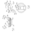
- Figure 1 shows a pump housing 10 having a bore 12 in which is mounted a pumping chamber assembly 14, for example, via a threaded connection 16 with associated seals 18 and cap 20.
- the assembly includes a generally cylindrical piston chamber wall 22, in which the pumping piston or plunger 24 is oriented for reciprocal motion.
- the portion 26 of the chamber In a retracted or bottom dead center position, the portion 26 of the chamber is filled, or partially filled with relatively low pressure feed fuel.
- the fuel in the pumping chamber 26 is highly pressurized and discharged for ultimately delivery, such as by injection, to the engine cylinders.
- the piston mounting bore 12 opens to a cavity 28 of the housing where feed fuel is maintained at a relatively low pressure and where a rotating drive member, especially an eccentric drive member 30, is mounted for rotation about a drive axis.
- the piston bore extends radially, relative to the drive axis, through the housing to the cavity, and the piston 24 is oriented radially within the piston bore.
- the piston has a radially inner, driven end 32, preferably in the form of a bulb or portion of a sphere, and a radially outer pumping end 34.
- a sliding shoe 36 is provided for pivotally engaging the driven end 32 of the piston while sliding on the outer surface of the drive member 30, to convert the radial motion of the drive member to the reciprocal motion of the piston.
- one or more charging orifices 38 are situated at the driven end, adjacent the spherical head 32, for fluid communication with the low-pressure fuel and cavity 28.
- This orifice 38 can be formed in a notch or neck 40, from which the head 32 extends downwardly.
- a charging passage 42 extends from the charging orifice 38 in fluid communication with the pumping chamber 26, through the center of the piston 24.
- a check valve 44 with associated spring 46 are mounted in the charging passage 42, for permitting fuel flow therein during charging from the cavity, but preventing fuel from flowing back into the cavity 28 during pressurization of the fuel in the pumping chamber 26.
- a piston return spring such as a coil spring, is mounted at one end 48 to a shoulder on the cylinder wall 22, concentrically but exterior to the lower portion of piston 24, and has another end 50 bearing on a rim or flange portion 52 of a spring seat which has a inner portion 54 bearing on a shoulder of the notch 40 associated with head 32.
- the sliding shoe 36 has an upper or top side on which a socket 56 is formed for the pivotal engagement via complementary concave surface to the convex surface formed by driven end 32 of the piston.
- the socket 56 and the spherical end 32 are both preferably formed at the surfaces of rotation about a common axis, e.g., the piston reciprocation axis.
- the shoe has an outer region 58 surrounding the driven end 32 of the piston and projecting into the piston bore 12. As will be described in greater detail below, all or some of such projection remains in the piston bore 12 during all positions of the piston 24 relative to the drive member 30.
- the return spring 50 extends longitudinally along a portion of the piston bore 12 externally of the piston 24 and acts on the driven end of the piston, and the outer region of shoe 58 projects into the piston bore in overlapped relation to the return spring when the piston bears against the central region of the shoe, as shown.
- the outer region 58 of the shoe overlaps the return spring 50 when the piston is at the bottom dead center position.
- the outer region 58 overlaps the return spring 50 when the piston is at the top dead center position as well.
- This is preferably implemented by configuring the piston 24 and shoe 36 in relation to the drive member 30, such that when the complementary surfaces or formations of the piston head 32 and the shoe socket 56 are engaged, these formation are in the piston bore 12 and the outer region 58 on the shoe extends into the piston bore 12 a greater distance than the engagement of the complementary formations.
- the outer region 58 of the shoe is annularly spaced about the socket 56 formed in the central region of the shoe, thereby defining an annular space between the central region and the outer region of the shoe.
- the rim portion 52 of the return spring seat, and the radially inner end 50 of the return spring, are situated in the space when the head 32 is fully engaged with the socket 56.
- the sliding shoe 36 preferably has top 60 and bottom 62 sides for cooperatively connecting the piston at the top with the drive member at the bottom.
- the sliding shoe 36 can be considered as having a base 64 having a concave bottom surface 66, a socket portion 56 projecting centrally on the top side, and a plurality of guide arms 58 projecting upwardly on the top side and spaced laterally from the socket portion.
- the plurality of guide arms preferably form a castellated, substantially annular rim around the socket portion.
- the upper surface 70 of the base is generally convex, and the arms project obliquely away from each other from the upper surface.
- the convex upper surface 70 of the base spans a first included solid angle 72 centered on the socket axis, and the arms project obliquely away from each other from the upper surface and span a second included solid angle 74 less than the first solid included angle.
- the plurality of guide arms preferably consists of four spaced apart arms 58a, 58b, 58c and 58d which together span a total of between 180 and 270 degs, of the rim circumference, with the spaces 76a, 76b, 76c and 76d between the arms together spanning a total of about 90 to 180 degs, of the circumference.
- each arm has substantially the same span.
- At least two of the arms can project from the top surface a greater distance than the projection of the socket.
- the relative length of the arms depends on the maximum piston travel.
- the shoes as shown on Figure 3 allow for larger eccentricity and by that for higher pump output, without the danger of ever leaving the bore. For smaller eccentricity the arms can be made shorter.
- the castellated arms 58 define U-shaped spaces 76a, 76b, 76c and 76d between adjacent arms, where the horizontal portion 78 of the U is defined by the top surface 70 of a step that projects a relatively shorter distance from the top surface of the base, and two facing side walls 82 and 84 of adjacent arms 58a, 58b that project a relatively longer distance from the base.
- two of the four castellated guide arms could be of lesser height, or could be eliminated.
- the bottom surface 66 of the shoe has plural grooves 86a,b to facilitate lubrication at the sliding interface
- the drive member 30 may be a cylinder having a drive member axis that is offset from the drive shaft axis (not shown), such that the drive member has an outer surface that is not circular with respect to the drive axis.
- Figures 6, 7 and 8 show that the bottom surface 66 of the shoe is also not circularly symmetric.
- neither the drive member surface nor the concave bottom surface 60 of the shoe 36 is circularly symmetric about the axis of socket 56.
- FIGs 1, 2A, 2B and 3 illustrate the problem solved by the present invention whereby in a control scheme where the inlet flow through the feed orifice 38 such as shown in Figure 1 or in some other manner, a smaller quantity of fuel is charged into the pumping chamber 26, relative to the full available charging volume defined by the difference in the top dead center and bottom dead center positions of the piston.
- a force component F1 originating from the pressure drop across the piston inlet (metering orifice plus opening pressure of the inlet check valve) acting over the effective area of the piston, trying to counter act the piston return spring force F2.
- the projecting arms of the sliding shoe according to applicant's invention not only physically retain the shoe within the piston mounting bore in the event of such misalignment or displacement of the shoe, but furthermore, the castellation of the arms by which spaces are present between adjacent arms, significantly reduces the hydraulic forces caused by the axial motion of the shoe through the liquid, which would otherwise further aggravate the problem described with respect to Figure 2A and 2B .
- FIGS 3 and 4 further illustrate the effect of the operation of the invention. These figures show that even in the unlikely event of the maximum possible separation (piston in top dead center position and drive member in bottom dead center position) the outer region of the shoe not only prevents the shoe from leaving the piston mounting bore, but also ensures that the ball or similar formation at the driven end of the piston finds its socket in the shoe as the eccentric again moves into what should be the top dead center position for the piston.
- the phantom line for the drive member in Figure 3 represents the maximum pumping position corresponding to top dead center of the piston, where the shoe would be engaged with the piston and the drive member would be engaged with the shoe.
- the return spring is not fully effective as the eccentric continues rotating to the position corresponding to the solid eccentric surface in Figure 3 , the shoe may remain on the surface of the eccentric while detaching from the piston. If this continues, the worst scenario the eccentric reaches the position corresponding to the bottom dead center of the piston, but the piston is still in its top dead center position.
- the phantom line show the position of the shoe if it continues to be carried away from the piston by the eccentric.
Landscapes
- Engineering & Computer Science (AREA)
- Mechanical Engineering (AREA)
- General Engineering & Computer Science (AREA)
- Chemical & Material Sciences (AREA)
- Combustion & Propulsion (AREA)
- Details Of Reciprocating Pumps (AREA)
- Reciprocating Pumps (AREA)
Claims (16)
- Pompe à piston radial comprenant un carter (10) définissant une cavité centrale (28) ; un élément d'entraînement (30) monté afin de pouvoir tourner dans la cavité (28) autour d'un axe d'entraînement ; au moins un alésage de montage de la chambre de pompage (12) s'étendant radialement par rapport audit axe, à travers le carter (10) vers ladite cavité (28) ; un piston (24) orienté radialement à l'intérieur de l'alésage de montage de la chambre de pompage (12) et présentant une extrémité de pompage radialement externe (34) et une extrémité entraînée radialement interne (32) coopérant avec l'élément d'entraînement (30) afin d'assurer un mouvement alternatif dans ledit alésage de montage de la chambre de pompage (12) entre des limites de déplacement de point mort haut et de point mort bas ; un sabot glissant (36) couplé à l'extrémité entraînée (32) du piston (24) et portant sur l'élément d'entraînement (30), afin d'assurer ladite coopération de telle sorte que ledit mouvement rotatif de l'élément d'entraînement (30) est transformé en un mouvement alternatif du piston (24) ; et un ressort de rappel (50) afin d'appliquer l'extrémité entraînée (32) du piston (24) vers le sabot (36) et l'élément d'entraînement (30), dans laquelle
le sabot glissant (36) comprend une zone centrale (56) comportant une partie de socle qui est couplée à l'extrémité entraînée (32) du piston (24) et une zone externe (58) entourant l'extrémité entraînée (32) du piston (24) et s'étendant dans l'alésage de montage de la chambre de pompage (12) sur une distance de telle sorte que pour toutes les positions du piston (24) par rapport à l'élément d'entraînement (30), au moins une partie de ladite zone externe (58) reste à l'intérieur de l'alésage de montage de la chambre de pompage (12), l'élément d'entraînement (30) présente une surface circulaire externe qui est décalée par rapport audit axe ;
l'extrémité entraînée (32) du piston (24) appuie avec possibilité de pivotement contre la zone centrale (56) du sabot (36) sans être fixée de manière rigide à ce dernier ;
le ressort de rappel (50) s'étend longitudinalement le long d'une partie de l'alésage de montage de la chambre de pompage (12) et agit sur l'extrémité entraînée (32) du piston (24) ;
ladite zone externe (58) s'étend dans ledit alésage de montage de la chambre de pompage (12) en relation de recouvrement par rapport au ressort de rappel (50) lorsque le piston (24) appuie contre la zone centrale (56) du sabot (36)
ladite zone externe (58) recouvre le ressort de rappel (50) lorsque le piston (24) est au point mort bas ; et
ladite saillie de zone externe (58) recouvre le ressort de rappel (50) lorsque le piston (24) est au point mort haut
caractérisée en ce que
le ressort de rappel (50) est situé de manière externe par rapport au piston (24), et
la zone externe (58) comprend une pluralité de bras de guidage (58a, 58b, 58c, 58d) s'étendant vers le haut à partir d'une face supérieure dudit sabot glissant (36) et qui sont espacés latéralement par rapport à ladite partie de socle (56). - Pompe selon la revendication 1, dans laquelle
le piston (24) comporte une formation sensiblement sphérique au niveau de l'extrémité entraînée (32) afin de reposer sur une formation complémentaire sur le sabot (36), un orifice de mise en charge (38) adjacent à la formation sphérique afin d'assurer la communication fluidique avec la cavité (28), et un passage de mise en charge (42) à l'intérieur du piston (24) à partir de l'orifice (38) jusqu'à une chambre de pompage (26) au niveau de l'extrémité de pompage (34) du piston (24) ; et
lorsque lesdites formations sont couplées, les formations sont dans l'alésage de montage de la chambre de pompage (12) et la zone externe (58) sur le sabot (36) s'étend dans l'alésage de montage de la chambre de pompage (12) sur une distance supérieure à ladite formation complémentaire. - Pompe selon la revendication 4, dans laquelle
le piston (24) comporte une partie rétrécie (40) à partir de laquelle la formation sphérique s'étend en une partie de tête convexe ;
un siège de ressort est supporté sur ladite partie rétrécie (40) ; ledit ressort de rappel (50) est appuyé sur ledit siège de ressort ; et
ladite zone externe (58) recouvre ledit siège de ressort. - Pompe selon la revendication 3, dans laquelle
le siège de ressort présente une partie de collerette annulaire (52) afin de recevoir le ressort de rappel (50) ; et
la partie de collerette (52) du siège de ressort est située dans ledit espace annulaire. - Pompe selon la revendication 1, dans laquelle
l'élément d'entraînement (30) présente une surface circulaire externe qui est décalée par rapport audit axe ;
l'extrémité entraînée (32) du piston (24) comporte une partie rétrécie (40) à partir de laquelle s'étend une partie de tête convexe afin d'assurer un couplage pivotant contre la zone centrale (56) du sabot (36) sans être fixée de manière rigide à ce dernier ;
un siège de ressort est supporté dans ladite partie rétrécie (40) ;
ledit ressort de rappel (50) est appuyé sur ledit siège de ressort ; et
ladite zone externe (58) entoure ledit siège de ressort lorsque la tête est appuyée dans la zone centrale (56) du sabot (36). - Pompe selon la revendication 1, dans laquelle la zone externe (58) est une série annulaire de bras de guidage (58a, 58b, 58c, 58d) formant une collerette crénelée autour du socle.
- Pompe selon la revendication 6, dans laquelle la collerette crénelée consiste en quatre bras espacés (58) qui ensemble s'étendent sur un total compris entre 180 et 270 degrés environ de ladite partie annulaire, les espaces entre les bras (58) s'étendant ensemble sur un total compris entre 90 et 180 degrés environ de ladite partie annulaire.
- Pompe selon l'une quelconque des revendications 1 à 7, dans laquelle le sabot glissant (36) comprend une base (64) présentant une surface inférieure concave (66).
- Pompe selon la revendication 8, dans laquelle la pluralité de bras de guidage (58a, 58b, 58c, 58d) forme une collerette crénelée sensiblement annulaire, autour de la partie de socle (56).
- Pompe selon la revendication 9, dans laquelle la base (64) présente une surface supérieure convexe et les bras (58a, 58b, 58c, 58d) s'étendent de manière oblique à l'opposé l'un de l'autre à partir de ladite surface supérieure.
- Pompe selon la revendication 8, dans laquelle la surface inférieure (66) comporte au moins une rainure.
- Pompe selon la revendication 9, dans laquelle la pluralité de bras de guidage (58a, 58b, 58c, 58d) comporte quatre bras espacés (58) qui ensemble s'étendent sur un total compris entre 180 et 270 degrés environ de ladite partie annulaire, les espaces entre les bras (58) s'étendant ensemble sur un total compris entre 90 et 180 degrés environ de ladite partie annulaire.
- Pompe selon la revendication 12, dans laquelle chaque bras (58a, 58b, 58c, 58d) présente sensiblement la même étendue.
- Pompe selon la revendication 8, dans laquelle la base (64) présente une surface supérieure à partir de laquelle s'étend le socle (56), et les bras (58) s'étendent à partir de la surface supérieure sur une distance supérieure à celle du socle (56).
- Pompe selon la revendication 14, dans laquelle un espace en forme de "U" entre les bras adjacents (58a, 58b, 58c, 58d) est défini par un échelon qui s'étend sur une distance relativement plus courte à partir de la surface supérieure de la base (64) et deux parois latérales en regard de bras adjacents (58a, 58b, 58c, 58d) qui s'étendent sur une distance relativement plus longue à partir de la surface supérieure de la base (64).
- Pompe selon la revendication 1, dans laquelle ladite pluralité de bras de guidage (58a, 58b, 58c, 58d) comprend deux bras diamétralement opposés (58).
Applications Claiming Priority (5)
| Application Number | Priority Date | Filing Date | Title |
|---|---|---|---|
| US10/187,823 US6694950B2 (en) | 1999-02-17 | 2002-07-02 | Hybrid control method for fuel pump using intermittent recirculation at low and high engine speeds |
| US187823 | 2002-07-02 | ||
| US10/217,831 US6901844B2 (en) | 2002-07-02 | 2002-08-12 | Guided shoe for radial piston pump |
| US217831 | 2002-08-12 | ||
| PCT/US2003/020663 WO2004005701A1 (fr) | 2002-07-02 | 2003-07-01 | Patin guide pour pompe a piston radial |
Publications (2)
| Publication Number | Publication Date |
|---|---|
| EP1520098A1 EP1520098A1 (fr) | 2005-04-06 |
| EP1520098B1 true EP1520098B1 (fr) | 2010-03-10 |
Family
ID=30117794
Family Applications (1)
| Application Number | Title | Priority Date | Filing Date |
|---|---|---|---|
| EP03742355A Expired - Lifetime EP1520098B1 (fr) | 2002-07-02 | 2003-07-01 | Patin guide pour pompe a piston radial |
Country Status (4)
| Country | Link |
|---|---|
| US (1) | US6901844B2 (fr) |
| EP (1) | EP1520098B1 (fr) |
| AU (1) | AU2003281333A1 (fr) |
| WO (1) | WO2004005701A1 (fr) |
Families Citing this family (6)
| Publication number | Priority date | Publication date | Assignee | Title |
|---|---|---|---|---|
| ATE409215T1 (de) | 1998-05-05 | 2008-10-15 | Massachusetts Inst Technology | Emittierende polymere und vorrichtungen diese polymere enthaltend |
| DE102005043266A1 (de) * | 2004-10-15 | 2006-04-20 | Continental Teves Ag & Co. Ohg | Kolbenpumpe |
| WO2015031884A1 (fr) | 2013-08-30 | 2015-03-05 | Flow Control Llc. | Pompe de portion à haute viscosité |
| DE102014220937B4 (de) | 2014-10-15 | 2016-06-30 | Continental Automotive Gmbh | Antriebsvorrichtung zum Antreiben einer Kraftstoffhochdruckpumpe sowie Kraftstoffhochdruckpumpe |
| DE102014220839B4 (de) * | 2014-10-15 | 2016-07-21 | Continental Automotive Gmbh | Hochdruckpumpe für ein Kraftstoffeinspritzsystem einer Brennkraftmaschine |
| WO2016102114A1 (fr) * | 2014-12-24 | 2016-06-30 | Robert Bosch Gmbh | Pompe haute pression pour alimenter en carburant, de préférence du carburant pour moteur diesel, un moteur à combustion interne |
Family Cites Families (6)
| Publication number | Priority date | Publication date | Assignee | Title |
|---|---|---|---|---|
| US5364234A (en) * | 1992-05-20 | 1994-11-15 | Karl Eickmann | High pressure devices |
| DE19523283B4 (de) | 1995-06-27 | 2006-01-19 | Robert Bosch Gmbh | Pumpe, insbesondere Hochdruckpumpe für eine Kraftstoffeinspritzvorrichtung eines Verbrennungsmotors |
| US6694950B2 (en) | 1999-02-17 | 2004-02-24 | Stanadyne Corporation | Hybrid control method for fuel pump using intermittent recirculation at low and high engine speeds |
| US6183212B1 (en) | 1999-02-17 | 2001-02-06 | Stanadyne Automotive Corp. | Snap-in connection for pumping plunger sliding shoes |
| US6460510B1 (en) | 2000-05-30 | 2002-10-08 | Robert H. Breeden | Pump assembly and method |
| JP2003074439A (ja) * | 2001-06-19 | 2003-03-12 | Denso Corp | 燃料噴射ポンプ |
-
2002
- 2002-08-12 US US10/217,831 patent/US6901844B2/en not_active Expired - Lifetime
-
2003
- 2003-07-01 WO PCT/US2003/020663 patent/WO2004005701A1/fr not_active Application Discontinuation
- 2003-07-01 AU AU2003281333A patent/AU2003281333A1/en not_active Abandoned
- 2003-07-01 EP EP03742355A patent/EP1520098B1/fr not_active Expired - Lifetime
Also Published As
| Publication number | Publication date |
|---|---|
| WO2004005701A1 (fr) | 2004-01-15 |
| AU2003281333A1 (en) | 2004-01-23 |
| US6901844B2 (en) | 2005-06-07 |
| US20040025684A1 (en) | 2004-02-12 |
| EP1520098A1 (fr) | 2005-04-06 |
Similar Documents
| Publication | Publication Date | Title |
|---|---|---|
| US7524171B2 (en) | Radial piston fuel supply pump | |
| US7152518B2 (en) | Structure of fuel injection pump for extending service life | |
| US8820300B2 (en) | High pressure fuel supply pump | |
| US10041457B2 (en) | Pump unit | |
| KR20130086542A (ko) | 펌프, 특히 고압 연료 펌프 | |
| CN104358664B (zh) | 一种端面配油的无轴向力双列径向柱塞泵 | |
| EP1520098B1 (fr) | Patin guide pour pompe a piston radial | |
| JPH09112408A (ja) | 燃料ポンプ | |
| JP2008511787A (ja) | 内燃機関の燃料噴射装置のための高圧ポンプ | |
| EP2492506B1 (fr) | Tête de pompage | |
| US6358024B1 (en) | High capacity supply pump with simultaneous directly actuated plungers | |
| WO2017053223A1 (fr) | Pompe à piston unique avec charges latérales de piston réduites | |
| US6488478B2 (en) | High pressure fuel pump | |
| US5772413A (en) | Bellows type pump | |
| CN100532823C (zh) | 用于内燃机燃料喷射装置的高压泵的止回阀 | |
| EP2189658B1 (fr) | Ensemble de pompe à fluide | |
| US20020159903A1 (en) | Check valve | |
| WO2003078822A1 (fr) | Composants de pompe et procede | |
| EP1318302B1 (fr) | Pompe d'injection de carburant | |
| JP2001173816A (ja) | 逆止弁及びそれを用いた燃料噴射ポンプ | |
| US6098519A (en) | Fuel pump | |
| US20080223460A1 (en) | Poppet check valve for high pressure oil pump | |
| EP1489301B1 (fr) | Système d'entraînement pour une Pompe | |
| EP2184491A1 (fr) | Tête de pompe pour ensemble de pompe à carburant | |
| GB2309270A (en) | Radial plunger pump |
Legal Events
| Date | Code | Title | Description |
|---|---|---|---|
| PUAI | Public reference made under article 153(3) epc to a published international application that has entered the european phase |
Free format text: ORIGINAL CODE: 0009012 |
|
| 17P | Request for examination filed |
Effective date: 20050126 |
|
| AK | Designated contracting states |
Kind code of ref document: A1 Designated state(s): AT BE BG CH CY CZ DE DK EE ES FI FR GB GR HU IE IT LI LU MC NL PT RO SE SI SK TR |
|
| AX | Request for extension of the european patent |
Extension state: AL LT LV MK |
|
| DAX | Request for extension of the european patent (deleted) | ||
| RBV | Designated contracting states (corrected) |
Designated state(s): DE FR GB IT |
|
| 17Q | First examination report despatched |
Effective date: 20050916 |
|
| GRAP | Despatch of communication of intention to grant a patent |
Free format text: ORIGINAL CODE: EPIDOSNIGR1 |
|
| GRAS | Grant fee paid |
Free format text: ORIGINAL CODE: EPIDOSNIGR3 |
|
| GRAA | (expected) grant |
Free format text: ORIGINAL CODE: 0009210 |
|
| AK | Designated contracting states |
Kind code of ref document: B1 Designated state(s): DE FR GB IT |
|
| REG | Reference to a national code |
Ref country code: GB Ref legal event code: FG4D |
|
| REF | Corresponds to: |
Ref document number: 60331650 Country of ref document: DE Date of ref document: 20100422 Kind code of ref document: P |
|
| PLBE | No opposition filed within time limit |
Free format text: ORIGINAL CODE: 0009261 |
|
| STAA | Information on the status of an ep patent application or granted ep patent |
Free format text: STATUS: NO OPPOSITION FILED WITHIN TIME LIMIT |
|
| 26N | No opposition filed |
Effective date: 20101213 |
|
| REG | Reference to a national code |
Ref country code: FR Ref legal event code: PLFP Year of fee payment: 14 |
|
| REG | Reference to a national code |
Ref country code: FR Ref legal event code: PLFP Year of fee payment: 15 |
|
| REG | Reference to a national code |
Ref country code: FR Ref legal event code: PLFP Year of fee payment: 16 |
|
| PGFP | Annual fee paid to national office [announced via postgrant information from national office to epo] |
Ref country code: IT Payment date: 20220721 Year of fee payment: 20 Ref country code: GB Payment date: 20220727 Year of fee payment: 20 Ref country code: DE Payment date: 20220727 Year of fee payment: 20 |
|
| PGFP | Annual fee paid to national office [announced via postgrant information from national office to epo] |
Ref country code: FR Payment date: 20220725 Year of fee payment: 20 |
|
| P01 | Opt-out of the competence of the unified patent court (upc) registered |
Effective date: 20230523 |
|
| REG | Reference to a national code |
Ref country code: DE Ref legal event code: R071 Ref document number: 60331650 Country of ref document: DE |
|
| REG | Reference to a national code |
Ref country code: GB Ref legal event code: PE20 Expiry date: 20230630 |
|
| PG25 | Lapsed in a contracting state [announced via postgrant information from national office to epo] |
Ref country code: GB Free format text: LAPSE BECAUSE OF EXPIRATION OF PROTECTION Effective date: 20230630 |