EP1520098B1 - Guided shoe for radial piston pump - Google Patents
Guided shoe for radial piston pump Download PDFInfo
- Publication number
- EP1520098B1 EP1520098B1 EP03742355A EP03742355A EP1520098B1 EP 1520098 B1 EP1520098 B1 EP 1520098B1 EP 03742355 A EP03742355 A EP 03742355A EP 03742355 A EP03742355 A EP 03742355A EP 1520098 B1 EP1520098 B1 EP 1520098B1
- Authority
- EP
- European Patent Office
- Prior art keywords
- piston
- pump
- shoe
- arms
- drive member
- Prior art date
- Legal status (The legal status is an assumption and is not a legal conclusion. Google has not performed a legal analysis and makes no representation as to the accuracy of the status listed.)
- Expired - Lifetime
Links
Images


Classifications
-
- F—MECHANICAL ENGINEERING; LIGHTING; HEATING; WEAPONS; BLASTING
- F02—COMBUSTION ENGINES; HOT-GAS OR COMBUSTION-PRODUCT ENGINE PLANTS
- F02M—SUPPLYING COMBUSTION ENGINES IN GENERAL WITH COMBUSTIBLE MIXTURES OR CONSTITUENTS THEREOF
- F02M59/00—Pumps specially adapted for fuel-injection and not provided for in groups F02M39/00 -F02M57/00, e.g. rotary cylinder-block type of pumps
- F02M59/02—Pumps specially adapted for fuel-injection and not provided for in groups F02M39/00 -F02M57/00, e.g. rotary cylinder-block type of pumps of reciprocating-piston or reciprocating-cylinder type
- F02M59/04—Pumps specially adapted for fuel-injection and not provided for in groups F02M39/00 -F02M57/00, e.g. rotary cylinder-block type of pumps of reciprocating-piston or reciprocating-cylinder type characterised by special arrangement of cylinders with respect to piston-driving shaft, e.g. arranged parallel to that shaft or swash-plate type pumps
- F02M59/06—Pumps specially adapted for fuel-injection and not provided for in groups F02M39/00 -F02M57/00, e.g. rotary cylinder-block type of pumps of reciprocating-piston or reciprocating-cylinder type characterised by special arrangement of cylinders with respect to piston-driving shaft, e.g. arranged parallel to that shaft or swash-plate type pumps with cylinders arranged radially to driving shaft, e.g. in V or star arrangement
-
- F—MECHANICAL ENGINEERING; LIGHTING; HEATING; WEAPONS; BLASTING
- F02—COMBUSTION ENGINES; HOT-GAS OR COMBUSTION-PRODUCT ENGINE PLANTS
- F02M—SUPPLYING COMBUSTION ENGINES IN GENERAL WITH COMBUSTIBLE MIXTURES OR CONSTITUENTS THEREOF
- F02M59/00—Pumps specially adapted for fuel-injection and not provided for in groups F02M39/00 -F02M57/00, e.g. rotary cylinder-block type of pumps
- F02M59/02—Pumps specially adapted for fuel-injection and not provided for in groups F02M39/00 -F02M57/00, e.g. rotary cylinder-block type of pumps of reciprocating-piston or reciprocating-cylinder type
- F02M59/10—Pumps specially adapted for fuel-injection and not provided for in groups F02M39/00 -F02M57/00, e.g. rotary cylinder-block type of pumps of reciprocating-piston or reciprocating-cylinder type characterised by the piston-drive
- F02M59/102—Mechanical drive, e.g. tappets or cams
-
- F—MECHANICAL ENGINEERING; LIGHTING; HEATING; WEAPONS; BLASTING
- F04—POSITIVE - DISPLACEMENT MACHINES FOR LIQUIDS; PUMPS FOR LIQUIDS OR ELASTIC FLUIDS
- F04B—POSITIVE-DISPLACEMENT MACHINES FOR LIQUIDS; PUMPS
- F04B1/00—Multi-cylinder machines or pumps characterised by number or arrangement of cylinders
- F04B1/04—Multi-cylinder machines or pumps characterised by number or arrangement of cylinders having cylinders in star- or fan-arrangement
- F04B1/0404—Details or component parts
- F04B1/0408—Pistons
-
- F—MECHANICAL ENGINEERING; LIGHTING; HEATING; WEAPONS; BLASTING
- F04—POSITIVE - DISPLACEMENT MACHINES FOR LIQUIDS; PUMPS FOR LIQUIDS OR ELASTIC FLUIDS
- F04B—POSITIVE-DISPLACEMENT MACHINES FOR LIQUIDS; PUMPS
- F04B1/00—Multi-cylinder machines or pumps characterised by number or arrangement of cylinders
- F04B1/04—Multi-cylinder machines or pumps characterised by number or arrangement of cylinders having cylinders in star- or fan-arrangement
- F04B1/0404—Details or component parts
- F04B1/0426—Arrangements for pressing the pistons against the actuated cam; Arrangements for connecting the pistons to the actuated cam
Definitions
- the present invention relates to radial piston pumps and more particularly, to radial piston pumps of the type used in fuel supply systems for internal combustion engines.
- Radial piston pumps particularly the type used for pressurizing fuel for delivery to the combustion chambers of internal combustion engines, typically have a housing defining a central cavity and a drive member mounted about a drive axis for rotation in the cavity. At least one piston bore extends radially relative to the axis, through the housing to the cavity.
- a piston oriented radially within the piston bore has a radially outer pumping end and a radially inner driven end cooperating with the drive member for reciprocal movement in the piston bore between top dead center and bottom dead center travel limits.
- a sliding shoe engages the driven end of the piston and bears on the drive member, for providing the cooperation whereby the rotary movement of the drive member is converted to the reciprocal movement of the piston.
- a return spring urges the driven end of the piston toward the shoe and the drive member.
- the drive member is eccentric, i.e., it has an outer circular surface with a center that is offset with respect to the drive axis.
- the driven end of the piston bears pivotally against, without being rigidly attached to, the shoe, to accommodate the eccentric path of the drive member.
- the projecting rim is in the form of guide arms that are spaced apart to form a castellated, substantially annular rim around the socket portion, such that in the event of separation of the driven end of the piston from the socket and the bottom side of the shoe from the drive member, with a resulting "floating" and misorientation of the shoe, at least a portion of one and preferably two of the guide arms, remains within the mounting bore of the piston, thereby preventing the shoe from experiencing excessive misorientation or displacement into the cavity.
- Figure 1 shows a pump housing 10 having a bore 12 in which is mounted a pumping chamber assembly 14, for example, via a threaded connection 16 with associated seals 18 and cap 20.
- the assembly includes a generally cylindrical piston chamber wall 22, in which the pumping piston or plunger 24 is oriented for reciprocal motion.
- the portion 26 of the chamber In a retracted or bottom dead center position, the portion 26 of the chamber is filled, or partially filled with relatively low pressure feed fuel.
- the fuel in the pumping chamber 26 is highly pressurized and discharged for ultimately delivery, such as by injection, to the engine cylinders.
- the piston mounting bore 12 opens to a cavity 28 of the housing where feed fuel is maintained at a relatively low pressure and where a rotating drive member, especially an eccentric drive member 30, is mounted for rotation about a drive axis.
- the piston bore extends radially, relative to the drive axis, through the housing to the cavity, and the piston 24 is oriented radially within the piston bore.
- the piston has a radially inner, driven end 32, preferably in the form of a bulb or portion of a sphere, and a radially outer pumping end 34.
- a sliding shoe 36 is provided for pivotally engaging the driven end 32 of the piston while sliding on the outer surface of the drive member 30, to convert the radial motion of the drive member to the reciprocal motion of the piston.
- one or more charging orifices 38 are situated at the driven end, adjacent the spherical head 32, for fluid communication with the low-pressure fuel and cavity 28.
- This orifice 38 can be formed in a notch or neck 40, from which the head 32 extends downwardly.
- a charging passage 42 extends from the charging orifice 38 in fluid communication with the pumping chamber 26, through the center of the piston 24.
- a check valve 44 with associated spring 46 are mounted in the charging passage 42, for permitting fuel flow therein during charging from the cavity, but preventing fuel from flowing back into the cavity 28 during pressurization of the fuel in the pumping chamber 26.
- a piston return spring such as a coil spring, is mounted at one end 48 to a shoulder on the cylinder wall 22, concentrically but exterior to the lower portion of piston 24, and has another end 50 bearing on a rim or flange portion 52 of a spring seat which has a inner portion 54 bearing on a shoulder of the notch 40 associated with head 32.
- the sliding shoe 36 has an upper or top side on which a socket 56 is formed for the pivotal engagement via complementary concave surface to the convex surface formed by driven end 32 of the piston.
- the socket 56 and the spherical end 32 are both preferably formed at the surfaces of rotation about a common axis, e.g., the piston reciprocation axis.
- the shoe has an outer region 58 surrounding the driven end 32 of the piston and projecting into the piston bore 12. As will be described in greater detail below, all or some of such projection remains in the piston bore 12 during all positions of the piston 24 relative to the drive member 30.
- the return spring 50 extends longitudinally along a portion of the piston bore 12 externally of the piston 24 and acts on the driven end of the piston, and the outer region of shoe 58 projects into the piston bore in overlapped relation to the return spring when the piston bears against the central region of the shoe, as shown.
- the outer region 58 of the shoe overlaps the return spring 50 when the piston is at the bottom dead center position.
- the outer region 58 overlaps the return spring 50 when the piston is at the top dead center position as well.
- This is preferably implemented by configuring the piston 24 and shoe 36 in relation to the drive member 30, such that when the complementary surfaces or formations of the piston head 32 and the shoe socket 56 are engaged, these formation are in the piston bore 12 and the outer region 58 on the shoe extends into the piston bore 12 a greater distance than the engagement of the complementary formations.
- the outer region 58 of the shoe is annularly spaced about the socket 56 formed in the central region of the shoe, thereby defining an annular space between the central region and the outer region of the shoe.
- the rim portion 52 of the return spring seat, and the radially inner end 50 of the return spring, are situated in the space when the head 32 is fully engaged with the socket 56.
- the sliding shoe 36 preferably has top 60 and bottom 62 sides for cooperatively connecting the piston at the top with the drive member at the bottom.
- the sliding shoe 36 can be considered as having a base 64 having a concave bottom surface 66, a socket portion 56 projecting centrally on the top side, and a plurality of guide arms 58 projecting upwardly on the top side and spaced laterally from the socket portion.
- the plurality of guide arms preferably form a castellated, substantially annular rim around the socket portion.
- the upper surface 70 of the base is generally convex, and the arms project obliquely away from each other from the upper surface.
- the convex upper surface 70 of the base spans a first included solid angle 72 centered on the socket axis, and the arms project obliquely away from each other from the upper surface and span a second included solid angle 74 less than the first solid included angle.
- the plurality of guide arms preferably consists of four spaced apart arms 58a, 58b, 58c and 58d which together span a total of between 180 and 270 degs, of the rim circumference, with the spaces 76a, 76b, 76c and 76d between the arms together spanning a total of about 90 to 180 degs, of the circumference.
- each arm has substantially the same span.
- At least two of the arms can project from the top surface a greater distance than the projection of the socket.
- the relative length of the arms depends on the maximum piston travel.
- the shoes as shown on Figure 3 allow for larger eccentricity and by that for higher pump output, without the danger of ever leaving the bore. For smaller eccentricity the arms can be made shorter.
- the castellated arms 58 define U-shaped spaces 76a, 76b, 76c and 76d between adjacent arms, where the horizontal portion 78 of the U is defined by the top surface 70 of a step that projects a relatively shorter distance from the top surface of the base, and two facing side walls 82 and 84 of adjacent arms 58a, 58b that project a relatively longer distance from the base.
- two of the four castellated guide arms could be of lesser height, or could be eliminated.
- the bottom surface 66 of the shoe has plural grooves 86a,b to facilitate lubrication at the sliding interface
- the drive member 30 may be a cylinder having a drive member axis that is offset from the drive shaft axis (not shown), such that the drive member has an outer surface that is not circular with respect to the drive axis.
- Figures 6, 7 and 8 show that the bottom surface 66 of the shoe is also not circularly symmetric.
- neither the drive member surface nor the concave bottom surface 60 of the shoe 36 is circularly symmetric about the axis of socket 56.
- FIGs 1, 2A, 2B and 3 illustrate the problem solved by the present invention whereby in a control scheme where the inlet flow through the feed orifice 38 such as shown in Figure 1 or in some other manner, a smaller quantity of fuel is charged into the pumping chamber 26, relative to the full available charging volume defined by the difference in the top dead center and bottom dead center positions of the piston.
- a force component F1 originating from the pressure drop across the piston inlet (metering orifice plus opening pressure of the inlet check valve) acting over the effective area of the piston, trying to counter act the piston return spring force F2.
- the projecting arms of the sliding shoe according to applicant's invention not only physically retain the shoe within the piston mounting bore in the event of such misalignment or displacement of the shoe, but furthermore, the castellation of the arms by which spaces are present between adjacent arms, significantly reduces the hydraulic forces caused by the axial motion of the shoe through the liquid, which would otherwise further aggravate the problem described with respect to Figure 2A and 2B .
- FIGS 3 and 4 further illustrate the effect of the operation of the invention. These figures show that even in the unlikely event of the maximum possible separation (piston in top dead center position and drive member in bottom dead center position) the outer region of the shoe not only prevents the shoe from leaving the piston mounting bore, but also ensures that the ball or similar formation at the driven end of the piston finds its socket in the shoe as the eccentric again moves into what should be the top dead center position for the piston.
- the phantom line for the drive member in Figure 3 represents the maximum pumping position corresponding to top dead center of the piston, where the shoe would be engaged with the piston and the drive member would be engaged with the shoe.
- the return spring is not fully effective as the eccentric continues rotating to the position corresponding to the solid eccentric surface in Figure 3 , the shoe may remain on the surface of the eccentric while detaching from the piston. If this continues, the worst scenario the eccentric reaches the position corresponding to the bottom dead center of the piston, but the piston is still in its top dead center position.
- the phantom line show the position of the shoe if it continues to be carried away from the piston by the eccentric.
Description
- The present invention relates to radial piston pumps and more particularly, to radial piston pumps of the type used in fuel supply systems for internal combustion engines.
- Radial piston pumps, particularly the type used for pressurizing fuel for delivery to the combustion chambers of internal combustion engines, typically have a housing defining a central cavity and a drive member mounted about a drive axis for rotation in the cavity. At least one piston bore extends radially relative to the axis, through the housing to the cavity. A piston oriented radially within the piston bore has a radially outer pumping end and a radially inner driven end cooperating with the drive member for reciprocal movement in the piston bore between top dead center and bottom dead center travel limits. A sliding shoe engages the driven end of the piston and bears on the drive member, for providing the cooperation whereby the rotary movement of the drive member is converted to the reciprocal movement of the piston. A return spring urges the driven end of the piston toward the shoe and the drive member. For the type of pump to which the present invention is especially directed, the drive member is eccentric, i.e., it has an outer circular surface with a center that is offset with respect to the drive axis. The driven end of the piston bears pivotally against, without being rigidly attached to, the shoe, to accommodate the eccentric path of the drive member.
- Particularly in operational modes where the pumping chamber of the piston is not fully charged before the pressurization, or discharge, stroke of the piston, unbalanced forces can act on the shoe with potentially detrimental, if not disastrous, results. Such unbalanced forces can result in separation of the shoe from both the driven end of the piston and the drive member while the piston is at or near the top dead center position such that, despite the restorative forces of the return spring, the piston does not seat properly in the shoe, or in the worst scenario, the shoe is carried into the cavity, resulting in catastrophic damage to the pump.
- One type of pump and associated control scheme in which this problem can arise, and for which the invention is particularly suited, is described in
U.S. Application No. 10/187,823, filled on July 2, 2002 - Known from
WO 01/92709 A - It is thus an object of the present invention to improve the performance and reliability of the sliding shoe associated with the conversion of rotating motion of a drive member, to the reciprocal motion of the pumping pistons, in a radial piston pump.
- The object is solved with the features according to claim 1.
- The projecting rim is in the form of guide arms that are spaced apart to form a castellated, substantially annular rim around the socket portion, such that in the event of separation of the driven end of the piston from the socket and the bottom side of the shoe from the drive member, with a resulting "floating" and misorientation of the shoe, at least a portion of one and preferably two of the guide arms, remains within the mounting bore of the piston, thereby preventing the shoe from experiencing excessive misorientation or displacement into the cavity.
- The preferred embodiment will be described below with reference to the accompanying drawing, in which:
-
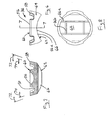
Figure 1 is a sectional view of a portion of a radial piston pump, showing the preferred form of the sliding shoe according to the invention, as well as the preferred relationship of the outer region of the sliding shoe to the pumping chamber mounting bore, when the piston is in the bottom dead center position; -
Figures 2A and 2B show a typical prior art sliding shoe in relation to the driven end of the piston and the drive member, for illustrating the unbalanced forces that give rise to the problem solved by the present invention; -
Figure 3 is a section view similar toFigure 1 , showing the relationship of the sliding shoe, the pumping chamber mounting bore, and the drive member, during the normal top dead center position of the piston, but with momentary separation between the driven end of the piston and the sliding shoe socket; -
Figure 4 is a section view similar toFigure 3 , showing the piston in the top dead center position, with the drive member in a different position resulting an even greater separation between the driven end of the piston and the socket of the sliding shoe, but with the sliding show retained within the pumping chamber mounting bore in accordance with the invention; -
Figure 5 is a perspective view of the preferred shape of the inventive sliding shoe; -
Figure 6 is an elevation view of the sliding shoe ofFigure 5 as seen along line V6; -
Figure 7 is a section view along line 7-7 ofFigure 6 ; and -
Figure 8 is a bottom view of the shoe ofFigure 5 . -
Figure 1 shows apump housing 10 having abore 12 in which is mounted apumping chamber assembly 14, for example, via a threadedconnection 16 with associatedseals 18 andcap 20. The assembly includes a generally cylindricalpiston chamber wall 22, in which the pumping piston or plunger 24 is oriented for reciprocal motion. In a retracted or bottom dead center position, theportion 26 of the chamber is filled, or partially filled with relatively low pressure feed fuel. Upon driving of the piston toward the top dead center position, the fuel in thepumping chamber 26 is highly pressurized and discharged for ultimately delivery, such as by injection, to the engine cylinders. - The piston mounting bore 12 opens to a
cavity 28 of the housing where feed fuel is maintained at a relatively low pressure and where a rotating drive member, especially an eccentric drive member 30, is mounted for rotation about a drive axis. Thus, the piston bore extends radially, relative to the drive axis, through the housing to the cavity, and the piston 24 is oriented radially within the piston bore. The piston has a radially inner, drivenend 32, preferably in the form of a bulb or portion of a sphere, and a radiallyouter pumping end 34. Asliding shoe 36 is provided for pivotally engaging the drivenend 32 of the piston while sliding on the outer surface of the drive member 30, to convert the radial motion of the drive member to the reciprocal motion of the piston. - In the illustrated embodiment, one or more
charging orifices 38 are situated at the driven end, adjacent thespherical head 32, for fluid communication with the low-pressure fuel andcavity 28. Thisorifice 38 can be formed in a notch or neck 40, from which thehead 32 extends downwardly. Acharging passage 42 extends from thecharging orifice 38 in fluid communication with thepumping chamber 26, through the center of the piston 24. A check valve 44 with associatedspring 46 are mounted in thecharging passage 42, for permitting fuel flow therein during charging from the cavity, but preventing fuel from flowing back into thecavity 28 during pressurization of the fuel in thepumping chamber 26. A piston return spring, such as a coil spring, is mounted at oneend 48 to a shoulder on thecylinder wall 22, concentrically but exterior to the lower portion of piston 24, and has another end 50 bearing on a rim orflange portion 52 of a spring seat which has ainner portion 54 bearing on a shoulder of the notch 40 associated withhead 32. - The sliding
shoe 36 has an upper or top side on which asocket 56 is formed for the pivotal engagement via complementary concave surface to the convex surface formed by drivenend 32 of the piston. Thesocket 56 and thespherical end 32 are both preferably formed at the surfaces of rotation about a common axis, e.g., the piston reciprocation axis. The shoe has anouter region 58 surrounding the drivenend 32 of the piston and projecting into thepiston bore 12. As will be described in greater detail below, all or some of such projection remains in thepiston bore 12 during all positions of the piston 24 relative to the drive member 30. The return spring 50 extends longitudinally along a portion of the piston bore 12 externally of the piston 24 and acts on the driven end of the piston, and the outer region ofshoe 58 projects into the piston bore in overlapped relation to the return spring when the piston bears against the central region of the shoe, as shown. In other words, theouter region 58 of the shoe overlaps the return spring 50 when the piston is at the bottom dead center position. As will be described in greater detail below, theouter region 58 overlaps the return spring 50 when the piston is at the top dead center position as well. This is preferably implemented by configuring the piston 24 andshoe 36 in relation to the drive member 30, such that when the complementary surfaces or formations of thepiston head 32 and theshoe socket 56 are engaged, these formation are in thepiston bore 12 and theouter region 58 on the shoe extends into the piston bore 12 a greater distance than the engagement of the complementary formations. - It can be appreciated from
Figure 1 , that theouter region 58 of the shoe is annularly spaced about thesocket 56 formed in the central region of the shoe, thereby defining an annular space between the central region and the outer region of the shoe. Therim portion 52 of the return spring seat, and the radially inner end 50 of the return spring, are situated in the space when thehead 32 is fully engaged with thesocket 56. - As may be further appreciated with reference to
Figures 1 ,5 ,6, 7 and 8 , thesliding shoe 36 preferably has top 60 andbottom 62 sides for cooperatively connecting the piston at the top with the drive member at the bottom. The slidingshoe 36 can be considered as having a base 64 having aconcave bottom surface 66, asocket portion 56 projecting centrally on the top side, and a plurality ofguide arms 58 projecting upwardly on the top side and spaced laterally from the socket portion. The plurality of guide arms preferably form a castellated, substantially annular rim around the socket portion. The upper surface 70 of the base is generally convex, and the arms project obliquely away from each other from the upper surface. In particular, the convex upper surface 70 of the base spans a first includedsolid angle 72 centered on the socket axis, and the arms project obliquely away from each other from the upper surface and span a second includedsolid angle 74 less than the first solid included angle. - The plurality of guide arms preferably consists of four spaced apart
arms spaces 76a, 76b, 76c and 76d between the arms together spanning a total of about 90 to 180 degs, of the circumference. Preferably each arm has substantially the same span. At least two of the arms can project from the top surface a greater distance than the projection of the socket. The relative length of the arms depends on the maximum piston travel. The shoes as shown onFigure 3 allow for larger eccentricity and by that for higher pump output, without the danger of ever leaving the bore. For smaller eccentricity the arms can be made shorter. - In the embodiment illustrated in
Figures 5-8 , thecastellated arms 58 define U-shapedspaces 76a, 76b, 76c and 76d between adjacent arms, where thehorizontal portion 78 of the U is defined by the top surface 70 of a step that projects a relatively shorter distance from the top surface of the base, and two facingside walls adjacent arms 58a, 58b that project a relatively longer distance from the base. - In order to reduce the shoe mass and flow restriction of the shoe while it moves up and down through the surrounding fuel, two of the four castellated guide arms could be of lesser height, or could be eliminated. Preferably, the
bottom surface 66 of the shoe hasplural grooves 86a,b to facilitate lubrication at the sliding interface, - It can be appreciated that the drive member 30 may be a cylinder having a drive member axis that is offset from the drive shaft axis (not shown), such that the drive member has an outer surface that is not circular with respect to the drive axis.
Figures 6, 7 and 8 show that thebottom surface 66 of the shoe is also not circularly symmetric. Thus, neither the drive member surface nor theconcave bottom surface 60 of theshoe 36 is circularly symmetric about the axis ofsocket 56. Moreover, it is not essential that the rim or projections ofouter region 58 be circularly symmetric about the socket axis. Rather, in the broadest embodiment, theouter region 58 would have two diametrically oppose projecting arms that together could span less than 180 deg. of the circular arc around the socket axis. -
Figures 1, 2A, 2B and3 illustrate the problem solved by the present invention whereby in a control scheme where the inlet flow through thefeed orifice 38 such as shown inFigure 1 or in some other manner, a smaller quantity of fuel is charged into the pumpingchamber 26, relative to the full available charging volume defined by the difference in the top dead center and bottom dead center positions of the piston. During the partial filling of the pumpingchamber 26, there will always be a force component F1, originating from the pressure drop across the piston inlet (metering orifice plus opening pressure of the inlet check valve) acting over the effective area of the piston, trying to counter act the piston return spring force F2. Although a small separation between the sliding shoe and the surface of the actuating eccentric drive member is beneficial because it helps regenerate the layer of lubricating fuel that was "squeezed out" during the previous pumping event as a consequence of the high pumping forces. However if the separation becomes too large, the pumping reaction forces as shown inFigures 2A and 2B will lead very quickly to even larger separation. If the sliding shoe is not retained in some manner, the shoe socket will lose engagement and slide in the direction of rotation, driven by the fictional forces F3 as well as hydraulic forces F4 generated by the flow of fuel displaced by the eccentric rotating inside of the pump cavity into the gap between the pump housing and the shaft. The shoe will subsequently be crushed by the eccentric, resulting in a catastrophic failure of the pump. - The projecting arms of the sliding shoe according to applicant's invention, not only physically retain the shoe within the piston mounting bore in the event of such misalignment or displacement of the shoe, but furthermore, the castellation of the arms by which spaces are present between adjacent arms, significantly reduces the hydraulic forces caused by the axial motion of the shoe through the liquid, which would otherwise further aggravate the problem described with respect to
Figure 2A and 2B . -
Figures 3 and 4 further illustrate the effect of the operation of the invention. These figures show that even in the unlikely event of the maximum possible separation (piston in top dead center position and drive member in bottom dead center position) the outer region of the shoe not only prevents the shoe from leaving the piston mounting bore, but also ensures that the ball or similar formation at the driven end of the piston finds its socket in the shoe as the eccentric again moves into what should be the top dead center position for the piston. - As a further explanation, the phantom line for the drive member in
Figure 3 represents the maximum pumping position corresponding to top dead center of the piston, where the shoe would be engaged with the piston and the drive member would be engaged with the shoe. However, if the return spring is not fully effective as the eccentric continues rotating to the position corresponding to the solid eccentric surface inFigure 3 , the shoe may remain on the surface of the eccentric while detaching from the piston. If this continues, the worst scenario the eccentric reaches the position corresponding to the bottom dead center of the piston, but the piston is still in its top dead center position. The phantom line show the position of the shoe if it continues to be carried away from the piston by the eccentric. It is evident that the outer regions of the shoe as shown in phantom inFigure 4 , are still within the piston mounting bore and therefore cannot, even if the shoe continues to slide relative the drive member, before hydraulic or other forces out of the piston mounting bore. The solid line rendition of the mounting shoe inFigure 4 , illustrates the worst case misorientation when the drive member is returning again toward approaching the position corresponding to top dead center of the piston (i.e., approaching the phantom line shown inFigure 3 for the drive member). The direction of this rotation would tilt the shoe but, in accordance with the present invention, the at least one arm of the shoe is restrained from moving excessively out of alignment, by contact with the spring seat for the return spring. Thus, as the eccentric continues rotation the driven end of the piston has an opportunity to reengage the socket and continue normal operation. - Although the invention has been described with respect to a radial piston pump in which the charging is controlled or restricted, it is also very beneficial for all other radial piston pumps actuated radially outwardly, particular by an eccentric drive member, inasmuch as even a miniscule amount of debris slowing down the motion of the piston, could also result in excessive separation resulting in catastrophic damage.
Claims (16)
- A radial piston pump having a housing (10) defining a central cavity (28); a drive member (30) mounted for rotation in the cavity (28) about a drive axis; at least one pumping chamber mounting bore (12) extending radially relative to said axis, through the housing (10) to said cavity (28); a piston (24) oriented radially within the pumping chamber mounting bore (12) and having a radially outer pumping end (34) and a radially inner driven end (32) cooperating with the drive member (30) for reciprocal movement in said pumping chamber mounting bore (12) between top dead center and bottom dead center travel limits; a sliding shoe (36) engaging the driven end (32) of the piston (24) and bearing on the drive member (30), for providing said cooperation whereby the rotary movement of the drive member (30) is converted to the reciprocal movement of the piston (24); and a return spring (50) for urging the driven end (32) of the piston (24) toward the shoe (36) and the drive member (30), wherein
the sliding shoe (36) has a central region (56) including a socket portion that engages the driven end (32) of the piston (24) and an outer region (58) surrounding the driven end (32) of the piston (24) and projecting into the pumping chamber mounting bore (12) a distance such that for all positions of the piston (24) relative to the drive member (30), at least a portion of said outer region (58) remains within the pumping chamber mounting bore (12), the drive member (30) has an outer circular surface that is offset with respect to said axis;
the driven end (32) of the piston (24) bears pivotally against without being rigidly attached to the central region (56) of the shoe (36);
the return spring (50) extends longitudinally along a portion of the pumping chamber mounting bore (12) and acts on the driven end (32) of the piston (24);
said outer region (58) projects into said pumping chamber mounting bore (12) in overlapped relation to the return spring (50) when the piston (24) bears against the central region (56) of the shoe (36)
said outer region (58) overlaps the return spring (50) when the piston (24) is at bottom dead center; and
said outer region (58) projection overlaps the return spring (50) when the piston (24) is at top dead center
characterized in that
the return spring (50) is externally located of the piston (24), and
the outer region (58) comprises a plurality of guide arms (58,a, 58b, 58c, 58d) projecting upwardly from a top side of said sliding shoe (36) and laterally spaced from said socket portion (56). - The pump of claim 1, wherein
the piston (24) has a Substantially spherical formation at the driven end (32) for seating with a complementary formation in the shoe (36), a charging orifice (38) adjacent the spherical formation for fluid communication with the cavity (28), and a charging passage (42) within the piston (24) from the orifice (38) to a pumping chamber (26) at the pumping end (34) of the piston (24); and
when said formations are engaged, the formations are in the pumping chamber mounting bore (12) and the outer region (58) on the shoe (36) extends into the pumping chamber mounting bore (12) a greater distance than said complementary formation. - The pump of claim 4, wherein
the piston (24) includes a neck portion (40) from which the spherical formation extends as a convex head portion;
a spring seat is supported in said neck portion (40);
said return spring (50) is seated on said spring seat; and
said outer region (58) overlaps said spring seat. - The pump of claim 3, wherein
the spring seat has an annular rim portion (52) for engaging the return spring (50); and
the rim portion (52) of the spring seat is situated in said annular space. - The pump of claim 1, wherein
the drive member (30) has an outer circular surface that is offset with respect to said axis;
the driven end (32) of the piston (24) includes a neck portion (40) from which a convex head portion extends into pivotal engagement against without being rigidly attached to the central region (56) of the shoe (36);
a spring seat is supported in said neck portion (40);
said return spring (50) is seated on said spring seat; and
said outer region (58) surrounds said spring seat when the head is seated in the central region (56) of the shoe (36). - The pump of claim 1, wherein the outer region (58) is an annular array of the guide arms (58a, 58b, 58c, 58d) forming a castellated rim around the socket.
- The pump of claim 6, wherein the castellated rim consists of four spaced apart arms (58) which together span a total of between about 180 and 270 degrees of said annulus, with the spaces between the arms (58) together spanning a total of about 90 to 180 degrees of said annulus.
- The pump of any of claims 1 to 7, wherein the sliding shoe (36) comprises a base (64) having a concave bottom surface (66).
- The pump of claim 8, wherein the plurality of guide arms (58a, 58b, 58c, 58d) form a castellated, substantially annular rim around the socket portion (56).
- The pump of claim 9, wherein the base (64) has a convex upper surface and the arms (58a, 58b, 58c, 58d) project obliquely away from each other from said upper surface.
- The pump of claim 8, wherein the bottom surface (66) includes at least one groove.
- The pump of claim 9, wherein the plurality of guide arms (58a, 58b, 58c, 58d) includes four spaced apart arms (58) which together span a total of between about 180 and 270 degrees of said annulus, with the spaces between the arms (58) together spanning a total of about 90 to 180 degrees of said annulus.
- The pump of claim 12, wherein each arm (58a, 58b, 58c, 58d) has substantially the same span.
- The pump of claim 8, wherein the base (64) has a top surface from which the socket (56) projects, and the arms (58) project from the top surface a greater distance than the socket (56).
- The pump of claim 14, wherein a "U" shaped space between adjacent arms (58a, 58b, 58c, 58d) is defined by a step that projects a relatively shorter distance from the top surface of the base (64) and two facing side walls of adjacent arms (58a, 58b, 58c, 58d) that project a relatively longer distance from the top surface of the base (64).
- The pump of claim 1, wherein said plurality of guide arms (58a, 58b, 58c, 58d) comprises two diametrically opposed arms (58).
Applications Claiming Priority (5)
| Application Number | Priority Date | Filing Date | Title |
|---|---|---|---|
| US187823 | 1988-04-29 | ||
| US217831 | 1994-03-25 | ||
| US10/187,823 US6694950B2 (en) | 1999-02-17 | 2002-07-02 | Hybrid control method for fuel pump using intermittent recirculation at low and high engine speeds |
| US10/217,831 US6901844B2 (en) | 2002-07-02 | 2002-08-12 | Guided shoe for radial piston pump |
| PCT/US2003/020663 WO2004005701A1 (en) | 2002-07-02 | 2003-07-01 | Guided shoe for radial piston pump |
Publications (2)
| Publication Number | Publication Date |
|---|---|
| EP1520098A1 EP1520098A1 (en) | 2005-04-06 |
| EP1520098B1 true EP1520098B1 (en) | 2010-03-10 |
Family
ID=30117794
Family Applications (1)
| Application Number | Title | Priority Date | Filing Date |
|---|---|---|---|
| EP03742355A Expired - Lifetime EP1520098B1 (en) | 2002-07-02 | 2003-07-01 | Guided shoe for radial piston pump |
Country Status (4)
| Country | Link |
|---|---|
| US (1) | US6901844B2 (en) |
| EP (1) | EP1520098B1 (en) |
| AU (1) | AU2003281333A1 (en) |
| WO (1) | WO2004005701A1 (en) |
Families Citing this family (6)
| Publication number | Priority date | Publication date | Assignee | Title |
|---|---|---|---|---|
| DE69939629D1 (en) | 1998-05-05 | 2008-11-06 | Massachusetts Inst Technology | Emitting polymers and devices containing these polymers |
| DE102005043266A1 (en) * | 2004-10-15 | 2006-04-20 | Continental Teves Ag & Co. Ohg | piston pump |
| US10267303B2 (en) | 2013-08-30 | 2019-04-23 | Flow Control Llc. | High viscosity portion pump |
| DE102014220937B4 (en) | 2014-10-15 | 2016-06-30 | Continental Automotive Gmbh | Drive device for driving a high-pressure fuel pump and high-pressure fuel pump |
| DE102014220839B4 (en) * | 2014-10-15 | 2016-07-21 | Continental Automotive Gmbh | High-pressure pump for a fuel injection system of an internal combustion engine |
| WO2016102114A1 (en) * | 2014-12-24 | 2016-06-30 | Robert Bosch Gmbh | High pressure pump for supplying fuel, preferably diesel, to an internal combustion engine |
Family Cites Families (6)
| Publication number | Priority date | Publication date | Assignee | Title |
|---|---|---|---|---|
| US5364234A (en) * | 1992-05-20 | 1994-11-15 | Karl Eickmann | High pressure devices |
| DE19523283B4 (en) * | 1995-06-27 | 2006-01-19 | Robert Bosch Gmbh | Pump, in particular high-pressure pump for a fuel injection device of an internal combustion engine |
| US6694950B2 (en) | 1999-02-17 | 2004-02-24 | Stanadyne Corporation | Hybrid control method for fuel pump using intermittent recirculation at low and high engine speeds |
| US6183212B1 (en) * | 1999-02-17 | 2001-02-06 | Stanadyne Automotive Corp. | Snap-in connection for pumping plunger sliding shoes |
| US6460510B1 (en) | 2000-05-30 | 2002-10-08 | Robert H. Breeden | Pump assembly and method |
| JP2003074439A (en) * | 2001-06-19 | 2003-03-12 | Denso Corp | Fuel injection pump |
-
2002
- 2002-08-12 US US10/217,831 patent/US6901844B2/en not_active Expired - Lifetime
-
2003
- 2003-07-01 AU AU2003281333A patent/AU2003281333A1/en not_active Abandoned
- 2003-07-01 WO PCT/US2003/020663 patent/WO2004005701A1/en not_active Application Discontinuation
- 2003-07-01 EP EP03742355A patent/EP1520098B1/en not_active Expired - Lifetime
Also Published As
| Publication number | Publication date |
|---|---|
| EP1520098A1 (en) | 2005-04-06 |
| US20040025684A1 (en) | 2004-02-12 |
| WO2004005701A1 (en) | 2004-01-15 |
| US6901844B2 (en) | 2005-06-07 |
| AU2003281333A1 (en) | 2004-01-23 |
Similar Documents
| Publication | Publication Date | Title |
|---|---|---|
| US7524171B2 (en) | Radial piston fuel supply pump | |
| US7152518B2 (en) | Structure of fuel injection pump for extending service life | |
| US8820300B2 (en) | High pressure fuel supply pump | |
| US10041457B2 (en) | Pump unit | |
| CN104358664B (en) | A kind of end face oil distributing without axial force biserial radial plunger pump | |
| WO1999043957A1 (en) | High capacity supply pump with simultaneous directly actuated plungers | |
| EP1520098B1 (en) | Guided shoe for radial piston pump | |
| JPH09112408A (en) | Fuel pump | |
| US8215925B2 (en) | Pump assembly and tappet therefor | |
| JP2008511787A (en) | High pressure pump for fuel injection device of internal combustion engine | |
| EP2492506B1 (en) | Pumping head | |
| WO2017053223A1 (en) | Single piston pump with reduced piston side loads | |
| US6488478B2 (en) | High pressure fuel pump | |
| US5772413A (en) | Bellows type pump | |
| CN100532823C (en) | Check valve, especially for a high pressure pump of a fuel injection device for an internal combustion engine | |
| EP2189658B1 (en) | Fluid Pump Assembly | |
| US20020159903A1 (en) | Check valve | |
| WO2003078822A1 (en) | Pump components and method | |
| EP1318302B1 (en) | Fuel injection pump | |
| EP0182159A1 (en) | Fuel injection pump | |
| JP2001173816A (en) | Check valve and fuel injection pump using the valve | |
| US6098519A (en) | Fuel pump | |
| US20080223460A1 (en) | Poppet check valve for high pressure oil pump | |
| EP1489301B1 (en) | Drive arrangement for a pump | |
| GB2309270A (en) | Radial plunger pump |
Legal Events
| Date | Code | Title | Description |
|---|---|---|---|
| PUAI | Public reference made under article 153(3) epc to a published international application that has entered the european phase |
Free format text: ORIGINAL CODE: 0009012 |
|
| 17P | Request for examination filed |
Effective date: 20050126 |
|
| AK | Designated contracting states |
Kind code of ref document: A1 Designated state(s): AT BE BG CH CY CZ DE DK EE ES FI FR GB GR HU IE IT LI LU MC NL PT RO SE SI SK TR |
|
| AX | Request for extension of the european patent |
Extension state: AL LT LV MK |
|
| DAX | Request for extension of the european patent (deleted) | ||
| RBV | Designated contracting states (corrected) |
Designated state(s): DE FR GB IT |
|
| 17Q | First examination report despatched |
Effective date: 20050916 |
|
| GRAP | Despatch of communication of intention to grant a patent |
Free format text: ORIGINAL CODE: EPIDOSNIGR1 |
|
| GRAS | Grant fee paid |
Free format text: ORIGINAL CODE: EPIDOSNIGR3 |
|
| GRAA | (expected) grant |
Free format text: ORIGINAL CODE: 0009210 |
|
| AK | Designated contracting states |
Kind code of ref document: B1 Designated state(s): DE FR GB IT |
|
| REG | Reference to a national code |
Ref country code: GB Ref legal event code: FG4D |
|
| REF | Corresponds to: |
Ref document number: 60331650 Country of ref document: DE Date of ref document: 20100422 Kind code of ref document: P |
|
| PLBE | No opposition filed within time limit |
Free format text: ORIGINAL CODE: 0009261 |
|
| STAA | Information on the status of an ep patent application or granted ep patent |
Free format text: STATUS: NO OPPOSITION FILED WITHIN TIME LIMIT |
|
| 26N | No opposition filed |
Effective date: 20101213 |
|
| REG | Reference to a national code |
Ref country code: FR Ref legal event code: PLFP Year of fee payment: 14 |
|
| REG | Reference to a national code |
Ref country code: FR Ref legal event code: PLFP Year of fee payment: 15 |
|
| REG | Reference to a national code |
Ref country code: FR Ref legal event code: PLFP Year of fee payment: 16 |
|
| PGFP | Annual fee paid to national office [announced via postgrant information from national office to epo] |
Ref country code: IT Payment date: 20220721 Year of fee payment: 20 Ref country code: GB Payment date: 20220727 Year of fee payment: 20 Ref country code: DE Payment date: 20220727 Year of fee payment: 20 |
|
| PGFP | Annual fee paid to national office [announced via postgrant information from national office to epo] |
Ref country code: FR Payment date: 20220725 Year of fee payment: 20 |
|
| P01 | Opt-out of the competence of the unified patent court (upc) registered |
Effective date: 20230523 |
|
| REG | Reference to a national code |
Ref country code: DE Ref legal event code: R071 Ref document number: 60331650 Country of ref document: DE |
|
| REG | Reference to a national code |
Ref country code: GB Ref legal event code: PE20 Expiry date: 20230630 |
|
| PG25 | Lapsed in a contracting state [announced via postgrant information from national office to epo] |
Ref country code: GB Free format text: LAPSE BECAUSE OF EXPIRATION OF PROTECTION Effective date: 20230630 |