EP2189658B1 - Ensemble de pompe à fluide - Google Patents
Ensemble de pompe à fluide Download PDFInfo
- Publication number
- EP2189658B1 EP2189658B1 EP08169804.5A EP08169804A EP2189658B1 EP 2189658 B1 EP2189658 B1 EP 2189658B1 EP 08169804 A EP08169804 A EP 08169804A EP 2189658 B1 EP2189658 B1 EP 2189658B1
- Authority
- EP
- European Patent Office
- Prior art keywords
- cam
- pump assembly
- fluid
- fluid pump
- bearing
- Prior art date
- Legal status (The legal status is an assumption and is not a legal conclusion. Google has not performed a legal analysis and makes no representation as to the accuracy of the status listed.)
- Active
Links
- 239000012530 fluid Substances 0.000 title claims description 40
- 238000005086 pumping Methods 0.000 claims description 27
- 230000001050 lubricating effect Effects 0.000 claims description 11
- 239000011248 coating agent Substances 0.000 claims description 10
- 238000000576 coating method Methods 0.000 claims description 10
- 239000000314 lubricant Substances 0.000 claims description 2
- 239000000446 fuel Substances 0.000 description 45
- 238000002347 injection Methods 0.000 description 7
- 239000007924 injection Substances 0.000 description 7
- 238000005553 drilling Methods 0.000 description 5
- 238000005461 lubrication Methods 0.000 description 5
- 229910019142 PO4 Inorganic materials 0.000 description 3
- 230000008878 coupling Effects 0.000 description 3
- 238000010168 coupling process Methods 0.000 description 3
- 238000005859 coupling reaction Methods 0.000 description 3
- NBIIXXVUZAFLBC-UHFFFAOYSA-K phosphate Chemical compound [O-]P([O-])([O-])=O NBIIXXVUZAFLBC-UHFFFAOYSA-K 0.000 description 3
- 239000010452 phosphate Substances 0.000 description 3
- 238000002485 combustion reaction Methods 0.000 description 2
- 238000010276 construction Methods 0.000 description 2
- 230000000694 effects Effects 0.000 description 2
- 239000000463 material Substances 0.000 description 2
- 239000004810 polytetrafluoroethylene Substances 0.000 description 2
- 229920001343 polytetrafluoroethylene Polymers 0.000 description 2
- 206010021580 Inadequate lubrication Diseases 0.000 description 1
- 230000004323 axial length Effects 0.000 description 1
- 230000006835 compression Effects 0.000 description 1
- 238000007906 compression Methods 0.000 description 1
- 238000007789 sealing Methods 0.000 description 1
- 238000000926 separation method Methods 0.000 description 1
- 230000003068 static effect Effects 0.000 description 1
Images


Classifications
-
- F—MECHANICAL ENGINEERING; LIGHTING; HEATING; WEAPONS; BLASTING
- F04—POSITIVE - DISPLACEMENT MACHINES FOR LIQUIDS; PUMPS FOR LIQUIDS OR ELASTIC FLUIDS
- F04B—POSITIVE-DISPLACEMENT MACHINES FOR LIQUIDS; PUMPS
- F04B1/00—Multi-cylinder machines or pumps characterised by number or arrangement of cylinders
- F04B1/12—Multi-cylinder machines or pumps characterised by number or arrangement of cylinders having cylinder axes coaxial with, or parallel or inclined to, main shaft axis
-
- F—MECHANICAL ENGINEERING; LIGHTING; HEATING; WEAPONS; BLASTING
- F02—COMBUSTION ENGINES; HOT-GAS OR COMBUSTION-PRODUCT ENGINE PLANTS
- F02M—SUPPLYING COMBUSTION ENGINES IN GENERAL WITH COMBUSTIBLE MIXTURES OR CONSTITUENTS THEREOF
- F02M59/00—Pumps specially adapted for fuel-injection and not provided for in groups F02M39/00 -F02M57/00, e.g. rotary cylinder-block type of pumps
- F02M59/02—Pumps specially adapted for fuel-injection and not provided for in groups F02M39/00 -F02M57/00, e.g. rotary cylinder-block type of pumps of reciprocating-piston or reciprocating-cylinder type
- F02M59/10—Pumps specially adapted for fuel-injection and not provided for in groups F02M39/00 -F02M57/00, e.g. rotary cylinder-block type of pumps of reciprocating-piston or reciprocating-cylinder type characterised by the piston-drive
- F02M59/102—Mechanical drive, e.g. tappets or cams
-
- F—MECHANICAL ENGINEERING; LIGHTING; HEATING; WEAPONS; BLASTING
- F04—POSITIVE - DISPLACEMENT MACHINES FOR LIQUIDS; PUMPS FOR LIQUIDS OR ELASTIC FLUIDS
- F04B—POSITIVE-DISPLACEMENT MACHINES FOR LIQUIDS; PUMPS
- F04B1/00—Multi-cylinder machines or pumps characterised by number or arrangement of cylinders
- F04B1/04—Multi-cylinder machines or pumps characterised by number or arrangement of cylinders having cylinders in star- or fan-arrangement
- F04B1/0404—Details or component parts
- F04B1/0426—Arrangements for pressing the pistons against the actuated cam; Arrangements for connecting the pistons to the actuated cam
-
- F—MECHANICAL ENGINEERING; LIGHTING; HEATING; WEAPONS; BLASTING
- F04—POSITIVE - DISPLACEMENT MACHINES FOR LIQUIDS; PUMPS FOR LIQUIDS OR ELASTIC FLUIDS
- F04B—POSITIVE-DISPLACEMENT MACHINES FOR LIQUIDS; PUMPS
- F04B1/00—Multi-cylinder machines or pumps characterised by number or arrangement of cylinders
- F04B1/12—Multi-cylinder machines or pumps characterised by number or arrangement of cylinders having cylinder axes coaxial with, or parallel or inclined to, main shaft axis
- F04B1/26—Control
- F04B1/30—Control of machines or pumps with rotary cylinder blocks
- F04B1/32—Control of machines or pumps with rotary cylinder blocks by varying the relative positions of a swash plate and a cylinder block
- F04B1/324—Control of machines or pumps with rotary cylinder blocks by varying the relative positions of a swash plate and a cylinder block by changing the inclination of the swash plate
- F04B1/326—Control of machines or pumps with rotary cylinder blocks by varying the relative positions of a swash plate and a cylinder block by changing the inclination of the swash plate using wedges
-
- F—MECHANICAL ENGINEERING; LIGHTING; HEATING; WEAPONS; BLASTING
- F04—POSITIVE - DISPLACEMENT MACHINES FOR LIQUIDS; PUMPS FOR LIQUIDS OR ELASTIC FLUIDS
- F04B—POSITIVE-DISPLACEMENT MACHINES FOR LIQUIDS; PUMPS
- F04B9/00—Piston machines or pumps characterised by the driving or driven means to or from their working members
- F04B9/02—Piston machines or pumps characterised by the driving or driven means to or from their working members the means being mechanical
- F04B9/04—Piston machines or pumps characterised by the driving or driven means to or from their working members the means being mechanical the means being cams, eccentrics or pin-and-slot mechanisms
- F04B9/042—Piston machines or pumps characterised by the driving or driven means to or from their working members the means being mechanical the means being cams, eccentrics or pin-and-slot mechanisms the means being cams
Definitions
- the invention relates to a fluid pump assembly and, in particular, but not exclusively, to a pump assembly for fuel.
- the pump assembly is suitable for use in a common rail fuel injection system for supplying high pressure fuel to a compression ignition (diesel) internal combustion engine.
- the invention has application in a pump assembly of the type in which an engine driven cam imparts reciprocating, pumping motion to a drive member.
- One known common rail fuel pump is of radial pump design and includes three pumping plungers arranged at equi-angularly spaced locations around an engine driven cam - such a pump is described in, for example, WO 2004/104409 .
- each plunger is mounted within a plunger bore provided in a pump head mounted to a main pump housing.
- the plungers are caused to reciprocate within their bores in a phased, cyclical manner.
- As the plungers reciprocate each causes pressurisation of fuel within a pump chamber defined at one end of the associated plunger bore.
- Fuel that is pressurised within the pump chambers is delivered to a common high pressure supply line and, from there, is supplied to a common rail or other accumulator volume, for delivery to the downstream injectors of the common rail fuel system.
- the fuel pump has an inlet valve for admitting fuel under low pressure and an outlet valve for letting out the pressurised fuel.
- the cam carries a cam rider that extends co-axially with the drive shaft for the cam.
- the cam rider is provided with a plurality of flat surfaces ("flats"), one for each of the plungers.
- An intermediate drive member in the form of a tappet co-operates with the flat on the cam rider and couples to the plunger so that, as the tappet is driven upon rotation of the cam, drive is imparted to the plunger.
- a fuel pump of radial pump design necessarily occupies a relatively high volume and, for some engine applications, this can be a disadvantage.
- the tappets are prone to wear due to the side loads experienced as they reciprocate, in use, and there can be significant damage to the tappet face that cooperates with the cam rider due to inadequate lubrication.
- US3208396 describes a so-called 'swash-plate' pump in which a rotatable cylinder barrel houses a plurality of pumping plungers. End portions of the pumping plungers cooperate with a swash-plate which causes the plungers to reciprocate as the cylinder barrel is driven in use:
- EP 1091 170 A which discloses the preamble of claim 1, describes a fluid pump assembly having a driven cam disc with reciprocating pistons axially slidable within a bore.
- a fluid pump assembly comprising a driven cam and a reciprocating member reciprocal within a bore provided in a pump housing as the cam is driven, in use, to cause pressurisation of fluid within a pump chamber.
- the fluid pump assembly further includes interface means between the cam and the reciprocating member which cause the reciprocating member to be driven to translate in a first, axial direction within the bore and driven to rotate continuously within the bore in a second, rotational direction, as the cam is driven.
- the reciprocating member is an intermediate drive member, typically in the form of a tappet, which is cooperable with a pumping plunger to cause pressurisation of fluid within the pump chamber as the pumping plunger is driven by the intermediate drive member.
- the reciprocating member is a pumping plunger which interfaces directly with the cam.
- the invention is particularly applicable to fuel injection systems for internal combustion engines in which a fuel pump assembly pressurises fuel to a relatively high pressure suitable for injection.
- a fuel pump assembly is particularly suitable for use in a common rail fuel injection system.
- the invention has wider application than fuel pumps for engines, and may be used as a pump for any other type of fluid also.
- the interface means includes a bevelled face of the reciprocating member and a correspondingly bevelled face of the cam which cooperate so as to cause axial and rotational motion of the reciprocating member as the cam rotates.
- the constant relative velocity between the parts aids lubrication so as to reduce the effects of wear due to friction.
- the reciprocating member rotates at substantially the same angular velocity as the cam.
- the fluid pump assembly preferably comprises an axial bearing for the cam which is defined by an axially-facing internal surface of the pump housing.
- the fluid pump assembly may further comprise a radial bearing for the cam which is defined by a radially-facing, internal surface of the pump housing.
- the cam may be provided with a low friction coating, for example a soft phosphate or PTFE coating, which deforms, in use, to the profile of the radial bearing.
- a low friction coating for example a soft phosphate or PTFE coating, which deforms, in use, to the profile of the radial bearing.
- the profile of the coating on the cam being matched with the profile of the radial bearing provides good conditions for promotion of a hydrodynamic film.
- the axial bearing may be provided with at least one recess to provide a volume for receiving lubricating fluid.
- the recess therefore provides for a supply of lubricating fluid to the axial bearing to aid lubrication between the rotating cam and the axial bearing.
- the axial bearing may include an un-recessed area which defines a load bearing surface for the cam.
- the axial bearing is provided with recess to define a region of weakness to allow the axial bearing to deflect, in use, thereby to create an increased volume for lubricating fluid between the axial bearing and the facing surface of the cam. Deflection of the axial bearing in this way opens up an enlarged gap between the cam and the axial bearing to encourage lubricating fluid to be drawn between the parts.
- the axial bearing is further provided with a cut-away section to define a lead-in edge for lubricant drawn between the axial bearing and the facing surface of the cam.
- the fluid pump assembly may comprise at least two intermediate drive members (e.g. tappets) and at least two pumping plungers, each of the intermediate drive members being cooperable with a respective one of the plungers and each of the intermediate drive members being cooperable with a cam common to all intermediate drive members.
- the fluid pump assembly includes three intermediate drive members and three pumping plungers, associated pairs of the drive members and the pumping plungers being arranged at equi-angularly spaced locations about a central pump axis.
- the reciprocating members are pumping plungers which interface directly with the cam
- the pumping plungers are arranged at equi-angularly spaced locations about the central pump axis.
- the pump chambers are defined within the pump housing and are closed by a plate mounted to the pump housing.
- the pump chambers may be defined entirely within the pump housing.
- an output end of the drive shaft may extend rearward of the cam and act against a bearing defined by the pump housing so as to counter side loads applied to an input end of the drive shaft.
- Such an arrangement is particularly suitable for belt, chain or gear drive applications where the nature of the input drive causes side loads to be imparted to the drive shaft.
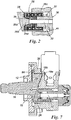
- a first embodiment of the fuel pump assembly 10 of the invention includes a pump housing having a first housing part 12 which is provided with a central bore for receiving a drive shaft 16 (only a part of which is shown).
- the first housing part includes a front plate 12a of the pump housing and a cylindrical body 12b towards the rear.
- the rear end of the drive shaft 16 carries a cam 18 which rotates with the drive shaft 16, in use.
- the front or input end of the drive shaft is driven by the engine through an Oldham coupling, as would be familiar to a person skilled in the art.
- the cam 18 is wedge-shaped and so has a thin end 18a and a thick end 18b with a bevelled contact surface 18c on its front face.
- the back face of the cam 18 is planar and acts against an axially-facing internal surface of the pump housing 12, which therefore acts as an axial bearing 22 for the cam 18 as it rotates.
- the outer surface of the cam, at its thick end 18b, bears against a radially-facing internal surface of the first housing part 12, which therefore acts as a radial bearing 24 for the cam 18 as it rotates.
- the pump assembly includes first and second reciprocating members, in the form of tappets 26, 28, each of which has a bevelled surface 26a, 28a, respectively, for contact with the correspondingly bevelled surface 18c of the cam 18.
- Each tappet 26, 28 is received within an associated tappet bore provided in a second housing part 30 mounted to the first housing part 12, and is coupled to an associated pumping plunger, 32, 34 respectively, in axial alignment with its tappet 26, 28.
- the tappets 26, 28 therefore form an intermediate drive member between the cam 18 and the associated plunger 32, 34.
- Each pumping plunger 32, 34 is received within an associated plunger bore provided in the second housing part 30.
- An end of the pumping plunger 32, 34 remote from the tappet 26, 28 defines an internal surface of a pump chamber 33, 35 which receives fuel to be pressurised during a plunger pumping stroke, in use, as described in further detail below.
- each tappet 26 takes the form of a bucket tappet of generally U-shaped cross section having a base 26b, which defines the bevelled contact surface 26a, and a cylindrical upper body 26c.
- the tappet Within the internal volume of the tappet 26, on the side of the base 26b opposed to the bevelled contact surface 26a, the tappet includes a projection 26d which defines a contact surface for the associated plunger 32.
- a spring seat assembly for a plunger return spring 37 is received within the internal volume of the tappet 26 defined within the cylindrical upper body 26c. The return spring 37 serves to provide a return load to the plunger 30 and the tappet 26 to effect a return stroke of the plunger, as described in further detail below.
- the spring seat assembly has two parts.
- a first part 36 is of top-hat construction and is located at the base of the plunger 32, the plunger 32 extending through a central bore of the first part 36.
- the first part 36 defines an abutment surface for one end of the return spring 37, the other end of the return spring 37 remote from the spring seat assembly 36, 38 abutting an internal surface 41 of the second housing part 30.
- a second part 38 of the spring seat assembly is an annular piece forms a push-fit on the base end of the plunger 32 and serves to retain the first part 36 of the assembly in place.
- the return spring 37 may be a smaller component located within the pump chamber 33, 35, rather than surrounding the plunger 32, 34.
- the pump chambers 33, 35 are closed by a plate 39 at the rear end of the pump assembly 10.
- the closure plate 39 is provided with a plurality of drillings to allow relatively low pressure fuel to be conveyed into the pump chambers 33, 35 and to allow pressurised fuel to be conveyed from the pump chambers 33, 35 to a pump outlet (not shown).
- An inlet drilling is provided for each of the pump chambers 33, 35, each inlet drilling having a respective spring-biased inlet valve 40, 42 through which relatively low pressure fuel passes to enter the associated pump chamber 33, 35, prior to pressurisation.
- An outlet drilling is provided for each of the pump chambers 33, 35, each outlet drilling having a respective spring-biased outlet valve 44, 46 through which pressurised fuel is delivered to the common outlet of the pump assembly when the pressure level in the pump chambers 33, 55 reaches a predetermined amount.
- the common outlet is connected to a common rail or accumulator volume of the fuel injection system, from where fuel is delivered to the fuel injectors of the engine.
- the outlet valve 44 is closed under its spring force.
- the pump chamber 33 fills with fuel at relatively low pressure from a supply pump (e.g. transfer pump) through the inlet valve 40 which is open.
- a supply pump e.g. transfer pump
- the tappet and hence the plunger, to move inwardly within their bores to reduce the volume of the pump chamber 33.
- fuel pressure in the pump chamber 33 starts to increase and the force due to fuel pressure acting on the inlet valve 40 causes it to close.
- the pressure within the pump chamber 33 continues to rise as the plunger 32 continues through its pumping stroke, until such time as the pressure in the pump chamber 33 is sufficient to overcome the closing force of the outlet valve 44, which is then urged open to allow pressurised fuel to be delivered through the pump outlet.
- the tappet is driven to move axially within its bore, hence driving axial motion of the plunger.
- cooperation between the rotating bevelled surface 18c of the cam 18 and the correspondingly bevelled surface 26a of tappet 26 also means that the tappet is driven to rotate within its bore at the same angular velocity at which the cam 18 is driven by the drive shaft 16. The interface between the cam and the tappet therefore results in a deliberately driven, continuous rotation of the tappet about its axis.
- the spring seat assembly is configured such that the frictional force between the return spring 37 and the first part 36 of the spring seat assembly is greater than the frictional force between the second and first parts 38, 36 of the spring seat assembly.
- the plunger 32 may also rotate, whereas the first part 36 of the spring seat assembly and the return spring 37 remain static. In this way relative movement between the end of the return spring 37 and the internal surface 41 of the second housing part 30 is prevented, to avoid unwanted wear, whilst the plunger 32 is allowed to rotate. Unwanted relative movement between the first part 36 of the spring seat assembly and the return spring 37 is also avoided.
- the second tappet 28 and the second plunger 34 are driven in a similar manner to operate in phased, cyclical motion with the first tappet/plunger 26/32, with both pump chambers 33, 35 filling a common rail with pressurised fuel through the respective outlet valves 44, 46.
- a clearance between each tappet and its tappet bore provides a volume for lubricating fluid and so, due to the relative motion between the rotating tappet and its bore, lubrication of parts is promoted to reduce wear.
- the return load on the cam 18 due to pressurised fuel within the pump chamber 33 is exerted on the cam 18 in a direction perpendicular to the bevel angle of the cam surface 18c.
- the thick end 18b of the cam 18 bears against the radially-facing internal surface of the first housing part 12, which therefore acts as a radial bearing 24 for the cam 18 as it rotates.
- the rear face 18d of the cam i.e. the face opposed to the bevelled surface 18c
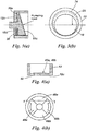
- Figure 3(b) illustrates a coating that is applied to the radially-facing surface of the cam 18. It is preferable for the surfaces of the cam 18 which bear against the axial and radial bearings 22, 24 to be provided with a soft lubricating coating, for example phosphate or PTFE.
- the dashed line illustrates the profile of the coating 25 on the cam 18, in use. As the coating 25 is soft, the coating deforms as the cam 18 rotates so as to conform to the profile of the bearing surface 24, hence providing good conditions for promotion of a hydrodynamic film.
- the soft phosphate coating is also applied to the bevelled face 18c of the cam 18 which cooperates with the bevelled surface 26a of the tappet.
- the axial bearing 22 is modified, on its front and rear faces, so as to aid lubrication between the parts 12,18.
- the axial bearing 22 includes first and second raised segments 46a, 46b, or pads, separated by first and second recessed segments 48a, 48b.
- the raised segments 46a, 46b are positioned so as to be axially aligned with a respective one of the tappets 26, 28 so as to absorb the tappet return load.
- the recesses 48a, 48b define an enlarged volume for lubricating fluid to aid lubrication between the cam 18 and the bearing 22 as the cam rotates.
- the opposite face 12c of the first housing part 12 to the axial bearing 22 is provided with a further recess 50 to define a weakened region of the first housing part 12.
- the weakened region of the pump housing 12 allows the housing to deflect causing a wedge-shaped gap (not shown) to open between the axial bearing 22 and the facing surface 18d of the cam 18. This provides a lead-in edge for lubricating fluid and allows fluid to be drawn between the parts 12, 18, allowing a hydrodynamic bearing to be generated between them as the cam 18 rotates.
- the axial bearing 22 may also be provided with a chamfer, radius or bevel (not shown) at the lead-in edge to further encourage lubricating fluid to be drawn between the parts 12, 18 as the cam rotates.
- FIG. 5 shows an embodiment of the invention which is appropriate for a belt, chain or gear drive coupling (not shown) between the engine and the drive shaft 16. Similar parts to those shown in Figures 1 to 4 are denoted with like reference numerals.
- a rear or output end of the drive shaft 16 extends further rearward into the pump assembly 10, and beyond the bevelled contact face 18c of the cam 18, to be received within a central bore provided in the second housing part 30.
- the internal surface of this central bore defines a radial bearing 52 which counters the tilting force acting on the front end of the drive shaft 16 and, hence, prevents unwanted tilt of the cam 18 as it rotates.
- the thin end 18a of the cam 18 is provided with an axially-extending flange 54, the outer surface of which bears on the radially-facing internal surface 56 of the pump housing 12.
- the axially-extending flange 54 bearing against the radially-facing internal surface 56 of the pump housing 12 counters the translation force acting on the front end of the drive shaft 16 and, hence, prevents unwanted translation of the cam 18 as it rotates.
- the bearing arrangement 52, 54, 56 of Figure 5 therefore prevents unwanted tilting and translation of the cam 18 due to side loading of the drive shaft 16 at its front end.
- the pump assembly in Figure 5 is of greater width than that in Figure 1 due to the need for the drive shaft 16 to extend further rearward into the pump housing 12, 30, and beyond the cam 18, to define the rear bearing 52, and hence the need for separation between the tappets 26, 28 to be greater.
- the width is also increased due to the provision of the flange 54 on the cam 18.
- the radially-facing internal surface of the pump housing provides a bearing surface 24 for the wide end 18b of the cam 18 and the axially-facing internal surface 22 of the pump housing 12 defines a bearing surface for the front face of the cam 18, as in the Figure 1 embodiment.
- FIG. 6 Another alternative bearing arrangement suitable for use with a belt, chain or gear drive is shown in Figure 6 .
- the drive shaft 16 extends further into the second housing part 30 and beyond the cam 18 so as to define a radial bearing 52 at the rear end of the drive shaft 16 which counters the tilting force applied to the cam 18 due to the side loads at the front end of the drive shaft 16.
- the flange on the thin end 18a of the cam 18 is removed, and instead the cam 18 is made of increased thickness in this region 18a' (i.e. the length of the cam along the axis of the drive shaft is increased at its thinnest end).
- the thin end 18a' of the cam 18 is therefore of greater thickness than in Figure 5 and bears against the radially-facing internal surface 56 of the first housing part 12 to counter the translation force acting on the cam 18 due to the side loading at the front end of the drive shaft 16.
- This arrangement results in a pump assembly of longer axial length than the Figure 5 embodiment due to the increased thickness of the cam 18 at region 18a', but one of reduced width due to the removal of the flange 54 in the Figure 5 embodiment.
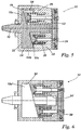
- FIG. 7 A further alternative embodiment is shown in Figure 7 which, again, is appropriate for use with a belt, chain or gear drive.
- the drive shaft 16 does not extend rearward beyond the cam 18, but instead the wide end 18b of the cam is provided with a radially-extending flange 58 which engages with a radially-extending, axially-facing surface 60 of the second housing part 30.
- the bearing provided by the radially-extending surface 60 of the second housing part 30 counters both the tilting and translation forces exerted on the cam 18 due to the side loads at the input end of the drive shaft 16.
- the pump housing in Figure 7 is still of two-part construction, the first housing part 12 which defines the axial bearing 22 is a much smaller component than in previous embodiments, with the second housing part 30 extending further towards the front end of the pump assembly 10 to define the bearing surface 60.
- the radially-extending flange 58 bears against the bearing surface 60 which counters the side loads on the input end of the drive shaft.
- the bearing surface 60 therefore takes the place of the bearing surfaces 52, 56 in Figures 1 , 5 and 6 .
- the pump assembly may include any number of plungers/tappets, depending on delivery requirements.
- the pump assembly may include three plungers (not shown), each having an associated tappet 126, 226, 326 which cooperates with a common bevelled cam 18.
- the tappets 126, 226, 326, and their associated plungers are arranged at equi-angularly spaced locations around a central axis of the pump assembly which is aligned with the drive shaft axis.
- Another arrangement of the bearings involves removing the flange 58 in the Figure 7 embodiment, and creating a bearing between a flat portion 18e of the front face of the cam (i.e. a portion that isn't bevelled) and the facing surface of the second housing part 30.
- the pump assembly has two axial bearings (at 22 and 18e), facing in opposite directions, to counter the side loads on the input end of the drive shaft 16.
- the tappets 26, 26, 126, 226, 326 of previous embodiments may be removed altogether and the bevelled surface 18c of the cam 18 may act directly on a correspondingly bevelled surface 32a, 34a of the reciprocating plungers 32, 34.
- a single plunger, or more than two plungers may be provided to interface directly with the bevelled cam 18, again avoiding the need for an intermediate drive member.
- the rear closure plate 39 in Figures 1 , 5 , 6 , 7 and 9 may be replaced by a housing part (not shown) which includes regions extending into the second housing part 30 so as to define the plunger sealing lengths and the pump chambers 33, 35.
- the main pump housing 30 does not have to have the required material strength to accommodate the high pressures of fuel within the pump chambers 33, 35, and only the closure plate 39 needs to be made from high-strength, expensive material.
Landscapes
- Engineering & Computer Science (AREA)
- Mechanical Engineering (AREA)
- General Engineering & Computer Science (AREA)
- Chemical & Material Sciences (AREA)
- Combustion & Propulsion (AREA)
- Fuel-Injection Apparatus (AREA)
- Reciprocating Pumps (AREA)
Claims (13)
- Ensemble formant pompe à fluide, comprenant :une came entraînée (18) ;un élément en va-et-vient (26, 28 ; 126, 226, 326 ; 32, 34) capable de va-et-vient dans un perçage ménagé dans un boîtier de pompe (12, 30) lorsque la came (18) est entraînée, en utilisation, pour provoquer une pressurisation du fluide à l'intérieur d'une chambre de pompe (33, 35) ; etcaractérisé en ce que ledit ensemble formant pompe à fluide comprend un moyen interface (26a, 28a ; 32a, 34a ; 18c) entre la came (18) et l'élément en va-et-vient, qui est adapté à amener l'élément en va-et-vient à être entraîné de façon à effectuer une translation dans une direction axiale à l'intérieur du perçage et qui est adapté à amener ledit élément en va-et-vient à être entraîné pour tourner continuellement autour de son propre axe à l'intérieur du perçage dans une direction de rotation, lorsque la came (18) est entraînée.
- Ensemble formant pompe à fluide selon la revendication 1, dans lequel l'élément en va-et-vient est un élément d'entraînement intermédiaire (26, 28 ; 126, 226, 326), qui est capable de coopérer avec un plongeur de pompage (32, 34) pour provoquer une pressurisation du fluide à l'intérieur de la chambre de pompe (33, 35) lorsque le plongeur de pompage (32, 34) est entraîné par l'élément d'entraînement intermédiaire (26, 28 ; 126, 226, 326).
- Ensemble formant pompe à fluide selon la revendication 1, dans lequel l'élément en va-et-vient est un plongeur de pompage (32, 34) qui est directement en interface avec la came (18).
- Ensemble formant pompe à fluide selon l'une quelconque des revendications 1 à 3, dans lequel l'élément en va-et-vient (26, 28 ; 126, 226, 326 ; 32, 34) est en rotation sensiblement à la même vitesse angulaire que la came (18).
- Ensemble formant pompe à fluide selon l'une quelconque des revendications 1 à 4, dans lequel le moyen interface (26a, 28a, 18c) inclut une face en biseau de l'élément en va-et-vient (26, 28) et une face en biseau correspondante (18c) de la came, qui coopèrent de manière à imposer un mouvement axial et un mouvement de rotation à l'élément en va-et-vient (26, 28) lorsque la came est en rotation.
- Ensemble formant pompe à fluide selon l'une quelconque des revendications 1 à 5, comprenant en outre un palier axial (22) pour la came, défini par une surface interne tournée en sens axial du boîtier de pompe (12) et/ou un palier radial (24) pour la came, défini par une surface interne tournée en sens radial du boîtier de pompe (12).
- Ensemble formant pompe à fluide selon la revendication 6, comprenant en outre un revêtement (25) appliqué sur la surface de la came et qui se déforme, en utilisation, vers le profil du palier radial (24).
- Ensemble formant pompe à fluide selon la revendication 6 ou 7, dans lequel le palier axial (22) est pourvu d'au moins un évidement (48a, 48b) pour constituer un volume afin de recevoir un fluide de lubrification.
- Ensemble formant pompe à fluide selon l'une quelconque des revendications 6 à 8, dans lequel le palier axial (22) inclut une zone dépourvue d'évidement (46a, 46b), qui définit une surface d'encaissement de charge pour la came (18).
- Ensemble formant pompe à fluide selon l'une quelconque des revendications 6 à 9, dans lequel le palier axial (22) est pourvu d'un évidement pour définir une région affaiblie (50) pour permettre au palier axial (22) de fléchir en utilisation, afin d'encourager ainsi l'huile de lubrification à être attirée entre le palier axial (22) et la came (18) lorsque celle-ci est en rotation.
- Ensemble formant pompe à fluide selon l'une quelconque des revendications 6 à 10, dans lequel le palier axial (22) est pourvu d'une section découpée pour définir un bord d'attaque pour le lubrifiant attiré entre le palier axial (22) et la came (18) lorsque celle-ci est en rotation.
- Ensemble formant pompe à fluide selon l'une quelconque des revendications 1 à 11, dans lequel les chambres de pompe sont soit définies à l'intérieur du boîtier de pompe (30) et sont fermées par une plaque (39) monté sur le boîtier de pompe (30), soit définies entièrement à l'intérieur du boîtier de pompe (30).
- Ensemble formant pompe à fluide selon l'une quelconque des revendications 1 à 12, dans lequel une extrémité de sortie de l'arbre d'entraînement (16) s'étend vers l'arrière de la came (18) et agit contre un palier (52) défini par le boîtier de pompe (30) de manière à s'opposer aux charges latérales appliquées à une extrémité d'entrée de l'arbre d'entraînement (16).
Priority Applications (3)
| Application Number | Priority Date | Filing Date | Title |
|---|---|---|---|
| EP08169804.5A EP2189658B1 (fr) | 2008-11-24 | 2008-11-24 | Ensemble de pompe à fluide |
| US12/615,467 US20100129246A1 (en) | 2008-11-24 | 2009-11-10 | Fluid pump assembly |
| JP2009257148A JP5108858B2 (ja) | 2008-11-24 | 2009-11-10 | 流体ポンプアッセンブリ |
Applications Claiming Priority (1)
| Application Number | Priority Date | Filing Date | Title |
|---|---|---|---|
| EP08169804.5A EP2189658B1 (fr) | 2008-11-24 | 2008-11-24 | Ensemble de pompe à fluide |
Publications (2)
| Publication Number | Publication Date |
|---|---|
| EP2189658A1 EP2189658A1 (fr) | 2010-05-26 |
| EP2189658B1 true EP2189658B1 (fr) | 2017-11-22 |
Family
ID=40565047
Family Applications (1)
| Application Number | Title | Priority Date | Filing Date |
|---|---|---|---|
| EP08169804.5A Active EP2189658B1 (fr) | 2008-11-24 | 2008-11-24 | Ensemble de pompe à fluide |
Country Status (3)
| Country | Link |
|---|---|
| US (1) | US20100129246A1 (fr) |
| EP (1) | EP2189658B1 (fr) |
| JP (1) | JP5108858B2 (fr) |
Families Citing this family (4)
| Publication number | Priority date | Publication date | Assignee | Title |
|---|---|---|---|---|
| CN103089562B (zh) * | 2013-02-04 | 2015-05-06 | 方亮 | 一种凸轮式柱塞泵 |
| RU2553593C1 (ru) * | 2013-11-26 | 2015-06-20 | Российская Федерация от имени которой выступает Министерство промышленности и торговли Российской Федерации | Топливный насос высокого давления аккумуляторной топливной системы двигателя внутреннего сгорания |
| DE102014219488A1 (de) * | 2014-09-25 | 2016-03-31 | Mahle International Gmbh | Pumpvorrichtung, insbesondere Axialkolbenpumpe, für eine Abwärmenutzungseinrichtung eines Kraftfahrzeugs |
| CN109185093B (zh) * | 2018-10-30 | 2024-02-20 | 郑州黄河众工机电科技有限公司 | 一种柱塞泵及组合泵 |
Family Cites Families (15)
| Publication number | Priority date | Publication date | Assignee | Title |
|---|---|---|---|---|
| US1491651A (en) * | 1921-12-01 | 1924-04-22 | Adrianus Anthony Wilton Reede | Crankless engine |
| US2842068A (en) * | 1954-10-05 | 1958-07-08 | Sundin Eric Olov | Piston pump |
| US2910008A (en) * | 1954-12-23 | 1959-10-27 | Bendix Aviat Corp | Pump |
| US2847938A (en) * | 1955-12-01 | 1958-08-19 | John T Gondek | Hydraulic pump |
| US3208396A (en) * | 1962-09-06 | 1965-09-28 | Budzich Tadeusz | Fluid pressure control system |
| US4753581A (en) * | 1987-02-10 | 1988-06-28 | Milton Roy Company | Constant suction pump for high performance liquid chromatography |
| JPH0638638B2 (ja) * | 1988-09-30 | 1994-05-18 | 富士写真フイルム株式会社 | バッテリの着脱制限機構 |
| EP0817916A4 (fr) * | 1995-03-20 | 2000-05-24 | Micropump Inc | Pompe a pistons multiples |
| US5655432A (en) * | 1995-12-07 | 1997-08-12 | Ford Motor Company | Swash plate with polyfluoro elastomer coating |
| DE19653158A1 (de) * | 1995-12-28 | 1997-07-03 | Unisia Jecs Corp | Axial-Plungerkolbenpumpe |
| DE69701848T2 (de) * | 1996-12-12 | 2000-10-26 | Sanden Corp | Schrägscheibenkompressor mit Lagerabdeckscheibe mit Radialflansch um die Schmierölzufuhr zum Antriebswellenlager zu gewährleisten |
| US6179574B1 (en) * | 1997-01-22 | 2001-01-30 | Jetec Company | Apparatus for pressurizing fluids and using them to perform work |
| GB9923786D0 (en) * | 1999-10-08 | 1999-12-08 | Eaton Williams Group Ltd | A steam-raising system |
| JP2003074439A (ja) * | 2001-06-19 | 2003-03-12 | Denso Corp | 燃料噴射ポンプ |
| GB0311814D0 (en) | 2003-05-22 | 2003-06-25 | Delphi Tech Inc | Pump assembly |
-
2008
- 2008-11-24 EP EP08169804.5A patent/EP2189658B1/fr active Active
-
2009
- 2009-11-10 US US12/615,467 patent/US20100129246A1/en not_active Abandoned
- 2009-11-10 JP JP2009257148A patent/JP5108858B2/ja active Active
Non-Patent Citations (1)
| Title |
|---|
| None * |
Also Published As
| Publication number | Publication date |
|---|---|
| EP2189658A1 (fr) | 2010-05-26 |
| US20100129246A1 (en) | 2010-05-27 |
| JP5108858B2 (ja) | 2012-12-26 |
| JP2010133402A (ja) | 2010-06-17 |
Similar Documents
| Publication | Publication Date | Title |
|---|---|---|
| US7108491B2 (en) | High pressure pump | |
| KR101559335B1 (ko) | 고압 연료 펌프 조립체 및 펌핑 플런저 | |
| KR19980071252A (ko) | 피스톤 펌프 | |
| US5626466A (en) | Piston pump | |
| JP3852756B2 (ja) | 燃料噴射ポンプ | |
| EP2189658B1 (fr) | Ensemble de pompe à fluide | |
| US20090126690A1 (en) | Fuel pump | |
| US20040091377A1 (en) | High-pressure fuel pump | |
| EP0972936A2 (fr) | Pompes volumétriques | |
| EP2050956B1 (fr) | Ensemble de pompe | |
| US6368071B1 (en) | High pressure fuel pump | |
| US5980214A (en) | Fluid pump with split plungers | |
| US11168677B2 (en) | Piston pump, particularly a high-pressure fuel pump for an internal combustion engine | |
| KR101591919B1 (ko) | 연료 펌프 조립체 | |
| WO2003078822A1 (fr) | Composants de pompe et procede | |
| EP2711546B1 (fr) | Agencement de poussoir et pompe | |
| EP1318302B1 (fr) | Pompe d'injection de carburant | |
| US10975816B2 (en) | Roller drive mechanism for GDI pump | |
| US20040213689A1 (en) | Fuel injection pump and rotation-linear motion transforming mechanism with safeguard | |
| JP5288267B2 (ja) | 燃料噴射ポンプ | |
| EP1489301B1 (fr) | Système d'entraînement pour une Pompe | |
| EP2184491A1 (fr) | Tête de pompe pour ensemble de pompe à carburant | |
| EP1705368A1 (fr) | Pompe à carburant | |
| EP2535584A1 (fr) | Ensemble de pompe | |
| EP3091220A1 (fr) | Pompe à carburant haute pression |
Legal Events
| Date | Code | Title | Description |
|---|---|---|---|
| PUAI | Public reference made under article 153(3) epc to a published international application that has entered the european phase |
Free format text: ORIGINAL CODE: 0009012 |
|
| AK | Designated contracting states |
Kind code of ref document: A1 Designated state(s): AT BE BG CH CY CZ DE DK EE ES FI FR GB GR HR HU IE IS IT LI LT LU LV MC MT NL NO PL PT RO SE SI SK TR |
|
| AX | Request for extension of the european patent |
Extension state: AL BA MK RS |
|
| 17P | Request for examination filed |
Effective date: 20101126 |
|
| AKX | Designation fees paid |
Designated state(s): AT BE BG CH CY CZ DE DK EE ES FI FR GB GR HR HU IE IS IT LI LT LU LV MC MT NL NO PL PT RO SE SI SK TR |
|
| AXX | Extension fees paid |
Extension state: RS Payment date: 20101126 Extension state: MK Payment date: 20101126 Extension state: BA Payment date: 20101126 Extension state: AL Payment date: 20101126 |
|
| RAP1 | Party data changed (applicant data changed or rights of an application transferred) |
Owner name: DELPHI INTERNATIONAL OPERATIONS LUXEMBOURG S.A.R.L |
|
| GRAP | Despatch of communication of intention to grant a patent |
Free format text: ORIGINAL CODE: EPIDOSNIGR1 |
|
| INTG | Intention to grant announced |
Effective date: 20170613 |
|
| GRAS | Grant fee paid |
Free format text: ORIGINAL CODE: EPIDOSNIGR3 |
|
| GRAA | (expected) grant |
Free format text: ORIGINAL CODE: 0009210 |
|
| AK | Designated contracting states |
Kind code of ref document: B1 Designated state(s): AT BE BG CH CY CZ DE DK EE ES FI FR GB GR HR HU IE IS IT LI LT LU LV MC MT NL NO PL PT RO SE SI SK TR |
|
| AX | Request for extension of the european patent |
Extension state: AL BA MK RS |
|
| REG | Reference to a national code |
Ref country code: GB Ref legal event code: FG4D |
|
| REG | Reference to a national code |
Ref country code: FR Ref legal event code: PLFP Year of fee payment: 10 |
|
| REG | Reference to a national code |
Ref country code: CH Ref legal event code: EP |
|
| REG | Reference to a national code |
Ref country code: IE Ref legal event code: FG4D |
|
| REG | Reference to a national code |
Ref country code: AT Ref legal event code: REF Ref document number: 948663 Country of ref document: AT Kind code of ref document: T Effective date: 20171215 |
|
| REG | Reference to a national code |
Ref country code: DE Ref legal event code: R096 Ref document number: 602008053041 Country of ref document: DE |
|
| REG | Reference to a national code |
Ref country code: NL Ref legal event code: MP Effective date: 20171122 |
|
| REG | Reference to a national code |
Ref country code: LT Ref legal event code: MG4D |
|
| REG | Reference to a national code |
Ref country code: AT Ref legal event code: MK05 Ref document number: 948663 Country of ref document: AT Kind code of ref document: T Effective date: 20171122 |
|
| PG25 | Lapsed in a contracting state [announced via postgrant information from national office to epo] |
Ref country code: FI Free format text: LAPSE BECAUSE OF FAILURE TO SUBMIT A TRANSLATION OF THE DESCRIPTION OR TO PAY THE FEE WITHIN THE PRESCRIBED TIME-LIMIT Effective date: 20171122 Ref country code: ES Free format text: LAPSE BECAUSE OF FAILURE TO SUBMIT A TRANSLATION OF THE DESCRIPTION OR TO PAY THE FEE WITHIN THE PRESCRIBED TIME-LIMIT Effective date: 20171122 Ref country code: NO Free format text: LAPSE BECAUSE OF FAILURE TO SUBMIT A TRANSLATION OF THE DESCRIPTION OR TO PAY THE FEE WITHIN THE PRESCRIBED TIME-LIMIT Effective date: 20180222 Ref country code: SE Free format text: LAPSE BECAUSE OF FAILURE TO SUBMIT A TRANSLATION OF THE DESCRIPTION OR TO PAY THE FEE WITHIN THE PRESCRIBED TIME-LIMIT Effective date: 20171122 Ref country code: NL Free format text: LAPSE BECAUSE OF FAILURE TO SUBMIT A TRANSLATION OF THE DESCRIPTION OR TO PAY THE FEE WITHIN THE PRESCRIBED TIME-LIMIT Effective date: 20171122 Ref country code: LT Free format text: LAPSE BECAUSE OF FAILURE TO SUBMIT A TRANSLATION OF THE DESCRIPTION OR TO PAY THE FEE WITHIN THE PRESCRIBED TIME-LIMIT Effective date: 20171122 |
|
| PG25 | Lapsed in a contracting state [announced via postgrant information from national office to epo] |
Ref country code: AT Free format text: LAPSE BECAUSE OF FAILURE TO SUBMIT A TRANSLATION OF THE DESCRIPTION OR TO PAY THE FEE WITHIN THE PRESCRIBED TIME-LIMIT Effective date: 20171122 Ref country code: LV Free format text: LAPSE BECAUSE OF FAILURE TO SUBMIT A TRANSLATION OF THE DESCRIPTION OR TO PAY THE FEE WITHIN THE PRESCRIBED TIME-LIMIT Effective date: 20171122 Ref country code: HR Free format text: LAPSE BECAUSE OF FAILURE TO SUBMIT A TRANSLATION OF THE DESCRIPTION OR TO PAY THE FEE WITHIN THE PRESCRIBED TIME-LIMIT Effective date: 20171122 Ref country code: BG Free format text: LAPSE BECAUSE OF FAILURE TO SUBMIT A TRANSLATION OF THE DESCRIPTION OR TO PAY THE FEE WITHIN THE PRESCRIBED TIME-LIMIT Effective date: 20180222 Ref country code: GR Free format text: LAPSE BECAUSE OF FAILURE TO SUBMIT A TRANSLATION OF THE DESCRIPTION OR TO PAY THE FEE WITHIN THE PRESCRIBED TIME-LIMIT Effective date: 20180223 |
|
| PG25 | Lapsed in a contracting state [announced via postgrant information from national office to epo] |
Ref country code: CZ Free format text: LAPSE BECAUSE OF FAILURE TO SUBMIT A TRANSLATION OF THE DESCRIPTION OR TO PAY THE FEE WITHIN THE PRESCRIBED TIME-LIMIT Effective date: 20171122 Ref country code: CY Free format text: LAPSE BECAUSE OF FAILURE TO SUBMIT A TRANSLATION OF THE DESCRIPTION OR TO PAY THE FEE WITHIN THE PRESCRIBED TIME-LIMIT Effective date: 20171122 Ref country code: EE Free format text: LAPSE BECAUSE OF FAILURE TO SUBMIT A TRANSLATION OF THE DESCRIPTION OR TO PAY THE FEE WITHIN THE PRESCRIBED TIME-LIMIT Effective date: 20171122 Ref country code: DK Free format text: LAPSE BECAUSE OF FAILURE TO SUBMIT A TRANSLATION OF THE DESCRIPTION OR TO PAY THE FEE WITHIN THE PRESCRIBED TIME-LIMIT Effective date: 20171122 Ref country code: LI Free format text: LAPSE BECAUSE OF NON-PAYMENT OF DUE FEES Effective date: 20171130 Ref country code: SK Free format text: LAPSE BECAUSE OF FAILURE TO SUBMIT A TRANSLATION OF THE DESCRIPTION OR TO PAY THE FEE WITHIN THE PRESCRIBED TIME-LIMIT Effective date: 20171122 Ref country code: CH Free format text: LAPSE BECAUSE OF NON-PAYMENT OF DUE FEES Effective date: 20171130 |
|
| REG | Reference to a national code |
Ref country code: DE Ref legal event code: R097 Ref document number: 602008053041 Country of ref document: DE |
|
| PG25 | Lapsed in a contracting state [announced via postgrant information from national office to epo] |
Ref country code: IT Free format text: LAPSE BECAUSE OF FAILURE TO SUBMIT A TRANSLATION OF THE DESCRIPTION OR TO PAY THE FEE WITHIN THE PRESCRIBED TIME-LIMIT Effective date: 20171122 Ref country code: RO Free format text: LAPSE BECAUSE OF FAILURE TO SUBMIT A TRANSLATION OF THE DESCRIPTION OR TO PAY THE FEE WITHIN THE PRESCRIBED TIME-LIMIT Effective date: 20171122 Ref country code: PL Free format text: LAPSE BECAUSE OF FAILURE TO SUBMIT A TRANSLATION OF THE DESCRIPTION OR TO PAY THE FEE WITHIN THE PRESCRIBED TIME-LIMIT Effective date: 20171122 Ref country code: LU Free format text: LAPSE BECAUSE OF NON-PAYMENT OF DUE FEES Effective date: 20171124 |
|
| REG | Reference to a national code |
Ref country code: BE Ref legal event code: MM Effective date: 20171130 |
|
| REG | Reference to a national code |
Ref country code: IE Ref legal event code: MM4A |
|
| PG25 | Lapsed in a contracting state [announced via postgrant information from national office to epo] |
Ref country code: MT Free format text: LAPSE BECAUSE OF NON-PAYMENT OF DUE FEES Effective date: 20171124 |
|
| PLBE | No opposition filed within time limit |
Free format text: ORIGINAL CODE: 0009261 |
|
| STAA | Information on the status of an ep patent application or granted ep patent |
Free format text: STATUS: NO OPPOSITION FILED WITHIN TIME LIMIT |
|
| 26N | No opposition filed |
Effective date: 20180823 |
|
| PG25 | Lapsed in a contracting state [announced via postgrant information from national office to epo] |
Ref country code: IE Free format text: LAPSE BECAUSE OF NON-PAYMENT OF DUE FEES Effective date: 20171124 |
|
| PG25 | Lapsed in a contracting state [announced via postgrant information from national office to epo] |
Ref country code: BE Free format text: LAPSE BECAUSE OF NON-PAYMENT OF DUE FEES Effective date: 20171130 Ref country code: SI Free format text: LAPSE BECAUSE OF FAILURE TO SUBMIT A TRANSLATION OF THE DESCRIPTION OR TO PAY THE FEE WITHIN THE PRESCRIBED TIME-LIMIT Effective date: 20171122 |
|
| REG | Reference to a national code |
Ref country code: DE Ref legal event code: R081 Ref document number: 602008053041 Country of ref document: DE Owner name: DELPHI TECHNOLOGIES IP LIMITED, BB Free format text: FORMER OWNER: DELPHI INTERNATIONAL OPERATIONS LUXEMBOURG S.A R.L., BASCHARAGE, LU |
|
| REG | Reference to a national code |
Ref country code: GB Ref legal event code: 732E Free format text: REGISTERED BETWEEN 20190222 AND 20190227 |
|
| PG25 | Lapsed in a contracting state [announced via postgrant information from national office to epo] |
Ref country code: HU Free format text: LAPSE BECAUSE OF FAILURE TO SUBMIT A TRANSLATION OF THE DESCRIPTION OR TO PAY THE FEE WITHIN THE PRESCRIBED TIME-LIMIT; INVALID AB INITIO Effective date: 20081124 Ref country code: MC Free format text: LAPSE BECAUSE OF FAILURE TO SUBMIT A TRANSLATION OF THE DESCRIPTION OR TO PAY THE FEE WITHIN THE PRESCRIBED TIME-LIMIT Effective date: 20171122 |
|
| PG25 | Lapsed in a contracting state [announced via postgrant information from national office to epo] |
Ref country code: TR Free format text: LAPSE BECAUSE OF FAILURE TO SUBMIT A TRANSLATION OF THE DESCRIPTION OR TO PAY THE FEE WITHIN THE PRESCRIBED TIME-LIMIT Effective date: 20171122 |
|
| PG25 | Lapsed in a contracting state [announced via postgrant information from national office to epo] |
Ref country code: PT Free format text: LAPSE BECAUSE OF FAILURE TO SUBMIT A TRANSLATION OF THE DESCRIPTION OR TO PAY THE FEE WITHIN THE PRESCRIBED TIME-LIMIT Effective date: 20171122 |
|
| PG25 | Lapsed in a contracting state [announced via postgrant information from national office to epo] |
Ref country code: IS Free format text: LAPSE BECAUSE OF FAILURE TO SUBMIT A TRANSLATION OF THE DESCRIPTION OR TO PAY THE FEE WITHIN THE PRESCRIBED TIME-LIMIT Effective date: 20180322 |
|
| P01 | Opt-out of the competence of the unified patent court (upc) registered |
Effective date: 20230327 |
|
| PGFP | Annual fee paid to national office [announced via postgrant information from national office to epo] |
Ref country code: GB Payment date: 20231013 Year of fee payment: 16 |
|
| PGFP | Annual fee paid to national office [announced via postgrant information from national office to epo] |
Ref country code: FR Payment date: 20231010 Year of fee payment: 16 Ref country code: DE Payment date: 20231010 Year of fee payment: 16 |
|
| REG | Reference to a national code |
Ref country code: DE Ref legal event code: R081 Ref document number: 602008053041 Country of ref document: DE Owner name: PHINIA DELPHI LUXEMBOURG SARL, LU Free format text: FORMER OWNER: DELPHI TECHNOLOGIES IP LIMITED, ST. MICHAEL, BB |