EP1520072B1 - Mehrstufige sortieranlage und sortierkorb für faserstoffsuspensionen - Google Patents
Mehrstufige sortieranlage und sortierkorb für faserstoffsuspensionen Download PDFInfo
- Publication number
- EP1520072B1 EP1520072B1 EP03725944A EP03725944A EP1520072B1 EP 1520072 B1 EP1520072 B1 EP 1520072B1 EP 03725944 A EP03725944 A EP 03725944A EP 03725944 A EP03725944 A EP 03725944A EP 1520072 B1 EP1520072 B1 EP 1520072B1
- Authority
- EP
- European Patent Office
- Prior art keywords
- dilution liquid
- dilution
- screen basket
- tubular
- screen
- Prior art date
- Legal status (The legal status is an assumption and is not a legal conclusion. Google has not performed a legal analysis and makes no representation as to the accuracy of the status listed.)
- Expired - Lifetime
Links
Images


Classifications
-
- D—TEXTILES; PAPER
- D21—PAPER-MAKING; PRODUCTION OF CELLULOSE
- D21D—TREATMENT OF THE MATERIALS BEFORE PASSING TO THE PAPER-MAKING MACHINE
- D21D5/00—Purification of the pulp suspension by mechanical means; Apparatus therefor
- D21D5/02—Straining or screening the pulp
- D21D5/16—Cylinders and plates for screens
-
- D—TEXTILES; PAPER
- D21—PAPER-MAKING; PRODUCTION OF CELLULOSE
- D21D—TREATMENT OF THE MATERIALS BEFORE PASSING TO THE PAPER-MAKING MACHINE
- D21D5/00—Purification of the pulp suspension by mechanical means; Apparatus therefor
- D21D5/02—Straining or screening the pulp
- D21D5/023—Stationary screen-drums
- D21D5/026—Stationary screen-drums with rotating cleaning foils
Definitions
- the present invention relates to a screening apparatus for screening pulp suspensions, comprising a housing, a tubular screen basket dividing the interior of the housing into a central chamber and an outer substantially annular chamber, an inlet member for supplying a suspension to be screened into one of the central chamber and outer chamber, and an accept outlet member for discharging a developed accept fraction of the suspension that has passed through the screen basket.
- the apparatus further comprises, a reject outlet member for discharging a developed reject fraction of the suspension, a rotor arranged in the housing for providing pressure and suction pulses in the suspension to be screened along the screen basket, and dilution means for supplying diluting liquid to one of the central chamber and outer chamber.
- the invention also relates to a screen basket for use in such an apparatus and methods of screening pulp suspensions in several screening stages.
- a very important step in the papermaking process is screening of fibre pulp suspensions.
- the pulp suspension is screened by several so-called pressure screening apparatuses of the type described above interconnected in a system of screening apparatuses, in which each screening apparatus represents a screening stage dependent on the other stages of the system.
- one single screening apparatus may be designed with several stages, typically two or three stages, incorporated into the same screen body.
- a variety of such multi-stage screening apparatuses of various designs have recently been introduced to the market.
- the increasing size of the paper making production lines of today has resulted in very large screening apparatus.
- Especially screening apparatus for low consistency pulp suspensions is large and has a very large screen basket, in order to accommodate high hydraulic loads.
- the screen baskets for different screening apparatuses typically are designed with about the same aspect ratio - length/diameter - regardless of size, so that a large basket is very long.
- Another reason why many screen baskets are long is the fact that it is considerably cheaper to increase the size of a given screen by increasing the length of the screen basket as compared to increasing the diameter thereof.
- a long screen basket In a long screen basket the path of travel for debris particles will be long. In consequence, a long screen basket has the disadvantage that since the retention time for the individual particle that is to be rejected will be long the probability of acceptance or breakdown will be higher than in shorter screen basket. Furthermore, a long screen basket is likely to encounter problems with reject fraction thickening and will have lower capacity per unit surface area as well as reduced removal efficiency.
- Another known dilution arrangement includes revolving dilution water outlets integrated into the rotor.
- this kind of dilution arrangement it is difficult to get the pressurised dilution water from the screen housing into the rotor.
- There are seals between stationary and rotary parts of the apparatus that often have wear problems, so that fibres pass through the seals into the dilution water compartments and eventually plug the outlets for dilution water.
- Another known dilution arrangement includes stationary dilution water outlets below the screening zone, and integrated into the screen housing. With these fairly expensive known arrangements it is very difficult to transport the dilution water to the optimum destination in the screen basket.
- Swedish patent application No. 9601979-9 proposes a solution to the above noted problems and discloses a dilution arrangement, in which dilution water is introduced into a channel circumventing a wedge wire type of screen basket.
- the channel is formed by putting a lid over the space between two support rings on the screen basket.
- the dilution water is fed into the screen basket through screening slots provided on the mantle wall of the screen basket.
- a problem of this solution is that the flow of dilution water entering the inside of the screen basket through the many very fine screen slots is insufficient and cannot give enough penetration and mixing of the dilution water and the thickened reject fraction.
- Another problem is leakage of unknown quantities of water to the accept chamber located external to the screen basket through the axially open spaces at the outer narrow ends between the wedge shaped bars and the fixation and support rings, that constitute the top and bottom of the dilution water channel.
- a first object of the present invention is to provide a screening apparatus for screening pulp suspension in stages having a simple, inexpensive dilution means that supplies dilution liquid to an optimum destination in the screen basket for efficient dilution of the reject fraction.
- a second object of the invention is to provide a screen basket for use in the screening apparatus of the invention and also for replacing worn out screen baskets in existing screening apparatuses.
- a third object of the invention is to provide a method of screening pulp suspension in stages so that the developed reject fraction is diluted in an optimum manner.
- the first object is obtained by a screening apparatus of the type described initially characterized in that the screen basket includes at least two separate tubular screen sections, and that the dilution means comprises at least one annular element axially interconnecting the two tubular screen sections and forming a tubular dilution liquid compartment extending at least substantially around the screen basket, the annular element forming a plurality of dilution liquid ejection passages between the dilution liquid compartment and one of the central chamber and outer chamber.
- the required amount and velocity of the dilution liquid jets sprayed from the ejection passages to provide efficient dilution of the reject fraction is easy to achieve by properly designing the size of the ejection passages.
- one of the accept outlet member and reject outlet member forms an outlet passage from the outer chamber
- the dilution means comprises at least one dilution liquid supply conduit extending through the outlet passage to the annular element, to supply dilution liquid from outside the housing to the dilution liquid compartment.
- the outlet member may include a releasable outlet portion situated outside the housing, wherein the dilution liquid supply conduit extends through the wall of the releasable outlet portion.
- the dilution means comprises first and second dilution liquid supply conduits connected to the annular element at different places thereon. This embodiment provides a more even distribution of dilution liquid into the screen basket.
- the tubular dilution liquid compartment may extend in a closed loop around the screen basket, and the dilution liquid supply conduit may be arranged to direct the dilution liquid into the dilution liquid compartment such that the dilution liquid flows in one direction along said closed loop.
- the flow of dilution liquid circling in the dilution liquid compartment will counteract fibres that might enter the compartment from depositing on the compartment wall.
- the second object of the invention is obtained by a screen basket, which comprises a tubular mantle wall provided with screen holes, and dilution means for supplying dilution liquid to one of the inside and outside of the tubular mantle wall.
- the screen basket is characterised in that the tubular mantle wall includes at least two separate tubular wall sections, and that the dilution means comprises at least one annular element axially interconnecting the two tubular wall sections of the mantle wall and forming a tubular dilution liquid compartment extending at least substantially around the tubular mantle wall, the annular element forming a plurality of dilution liquid ejection passages between the dilution liquid compartment and one of the inside and outside of the screen basket.
- An important advantage of the screen basket of the invention is that it is well suited for replacing worn out screen baskets in existing single-stage screening apparatuses, thereby functionally converting the existing apparatuses into multi-stage apparatuses.
- the ejection passages may have circular cross-sections or, alternatively, take the shape of slots.
- the tubular dilution liquid compartment has a rectangular cross-section and extends in a closed loop around the tubular mantle wall.
- the dilution means may comprise first and second dilution liquid supply inlets on the annular element positioned at different places thereon.
- the third object of the invention is obtained by a method of screening a pulp suspension by the use of a screening apparatus having a tubular screen basket.
- the method comprises:
- the suspension to be screened is normally fed into the internal side of the screen basket and is screened so that the primary reject fraction develops inside the screen basket, whereby the flow of dilution liquid is supplied to the inside of the screen basket and the secondary reject fraction develops inside the screen basket.
- the method may further comprise supplying the flow of dilution liquid in the form of jets having a velocity in the range of 2-10 m/s, preferably 4-8 m/s.
- the control of the flow of dilution liquid being supplied to the screen basket is based on an algorithm calculated as follows.
- Thickening is the result of that the probability for acceptance through the screen barrier always is higher for water than for fibre. It is defined as the consistency increase from the feed end to the reject end of the screen basket. Thickening varies with the type of pulp, the production rate and with most design and operating variables of a pressure screen.
- the thickening is the ratio F between reject consistency Cr and feed consistency Cf or the ratio between mass reject rate Rm and volumetric reject rate Rv .
- the input data required for this calculation is only feed - and final reject flow and the consistencies of these flows.
- the third object of the invention also is obtained by a method for three-stage screening. Accordingly, the alternative method comprises:
- the suspension to be screened is normally fed into the internal side of the screen basket.
- the suspension is screened so that the primary reject fraction develops inside the screen basket, whereby the first and second flows of dilution liquid are supplied to the inside of the screen basket and the secondary and tertiary reject fractions develop inside the screen basket
- (Rm) is the total mass reject rate over the whole screen, after the three stages.
- Retrofits for all types of screens with long baskets, e.g. all screen baskets longer (higher) than 600mm will benefit from the present invention. They will have increased capacity and/or efficiency by dividing a too long screening zone into a primary and a secondary stage. These positive effects are results of a more efficient utilization of the screen basket surface.
- Another possibility to take advantage of this new concept is to operate with a more gentle surface profile of the screen basket that defines the screen holes for better removal efficiency. A too aggressive surface profile is not required to meet capacity demands. Multi-stage dilution will also make it possible to reduce the RPM of the rotor. At lower RPM the screening apparatus will pull lower electric load.
- New product lines of screens can take advantage of this technology. No dilution arrangements will be required in the screen housing and/or in the screen rotor. A simpler and less expensive screen design can be used.
- the multi-stage screening apparatus of the invention can be designed with only one accept compartment and with less expensive process control.
- a two-stage screen with controlled mass reject rate based on state of the art technology requires four flow controls and two consistency controllers, whereas the multi-stage dilution technology according to the present invention requires only three and two controls respectively for the same information.
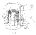
- FIG. 1 shows a screening apparatus according to the present invention for screening pulp suspensions, comprising a housing 2, an inlet member 4 releasably connected to a supply pipe 6 for supplying a suspension to be screened into the housing 2, a tubular screen basket 8 dividing the interior of the housing 2 into a central substantially cylindrical chamber 10 for receiving the suspension to be screened at one end 12 of the central chamber and a single outer annular accept chamber 14 for receiving an accept fraction of the suspension that has passed through the screen basket 8, an accept outlet member 16 forming an outlet passage 17 and releasably connected to an accept outlet pipe 18 for discharging the accept fraction from the accept chamber 14 and a reject outlet member 20 releasably connected to a reject outlet pipe 22 for discharging a reject fraction of the suspension from the central chamber 10 at the other end 24 thereof.
- a rotor 26 is arranged in the central chamber 10 for providing pressure and suction pulses in the suspension along the internal side of the screen basket 8.
- Dilution means 28 is provided for supplying diluting liquid
- the screen basket 8 comprises a cylindrical mantle wall 30 with screen holes taking the shape of slots.
- the mantle wall 30 is provided with an upper flange 32 and a lower flange 34 that seal against an upper shoulder 36 on the housing and a lower shoulder 38 on the housing, respectively.
- the mantle wall 30 is divided into two separate cylindrical sections 40 and 42, which are axially interconnected by an annular element 44 of the dilution means 28.
- the annular element 44 forms a tubular dilution liquid compartment 46 having a rectangular cross-section and extending around the mantle wall 30.
- the annular element 44 has a dilution liquid inlet opening 48 and a multiplicity of dilution liquid ejection passages 50 having circular cross-section and extending between the compartment 46 and the inside of the screen basket 8.
- a dilution liquid supply conduit 52 of the dilution means 28 for supplying dilution liquid from outside the housing 2 to the dilution liquid compartment 46 extends through the wall of the accept outlet pipe 18 and further through the outlet passage 17 of the accept outlet member 16 to the opening 48 of the annular element 44.
- the screen basket 8 described above is particularly suited for replacing traditional single stage screen baskets in old screening apparatuses. By utilizing the existing accept outlet member to connect the dilution liquid supply conduit there is no need for reconstructing the housing of the old apparatus.
- a fibre suspension to be screened is fed via the inlet member 4 to the screen basket 8 at the upper side 12 thereof.
- the suspension is screened along section 40 of the mantle wall 30, so that a primary accept fraction passes through the mantle wall 30 while a primary reject fraction develops inside the screen basket 8.
- the primary reject fraction is diluted by a controlled flow of dilution liquid sprayed through the ejection passages 50.
- the diluted primary reject fraction is screened along section 42 of the mantle wall 30, so that a secondary accept fraction passes through the mantle wall 30 while a secondary reject fraction develops inside the screen basket 8 and then is discharged from the screen basket 8 through the reject outlet member 20.
- the primary and secondary accept fractions are combined and discharged through the accept outlet member 16.
- the flow of dilution liquid through the ejection passages 50 is controlled in response to the consistency and flow of the suspension being fed to the screen basket 8 and the consistency and flow of the secondary reject fraction being discharged from the screen basket 8, so that the consistency of the primary reject fraction entering section 42 of the mantle wall 30 becomes substantially the same as the consistency of the suspension being fed into the screen basket 8.
- the suspension is supplied to the outer chamber 14 and a rotor is arranged in the outer chamber 14 to provide pressure and suction pulses in the suspension along the external side of the screen basket 8.
- the liquid ejection passages extend between the compartment 46 and the outside of the screen basket 8, so that the primary reject fraction that develops outside the screen basket 8 can be diluted by liquid jets from the ejection passages.
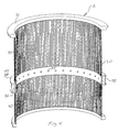
- Figure 2 shows a screening apparatus of the invention similar to the embodiment shown in figure 1 except that the screen basket and the dilution liquid supply are designed differently.
- the apparatus of figure 2 comprises a housing 54 provided with two dilution liquid inlet conduits 56 and 58, and a screen basket 60 provided with two dilution liquid inlet openings 62 and 64 connected to the conduits 56 and 58, respectively.
- This embodiment is suited for new screening apparatuses.
Landscapes
- Engineering & Computer Science (AREA)
- Mechanical Engineering (AREA)
- Paper (AREA)
- Separation Of Solids By Using Liquids Or Pneumatic Power (AREA)
- Hydroponics (AREA)
Claims (12)
- Siebvorrichtung zum Sieben von Pulpensuspensionen, umfassend ein Gehäuse (2; 54), einen rohrförmigen Siebkorb (8; 60), der das Innere des Gehäuses in eine Zentralkammer (10) und eine einzelne äußere im Wesentlichen ringförmige Kammer (14) unterteilt, ein Einlasselement (4) zum Zuführen einer zu siebenden Suspension in die Zentralkammer, ein Annahme-Auslasselement (16) zum Abgeben eines entwickelten Annahmeanteils der Suspension, die durch den Siebkorb in die einzelne äußere Kammer hindurchgetreten ist, ein Absonderungsauslasselement (20) zur Abgabe eines entwickelten Absonderungsanteils der Suspension, einen Rotor (26), der in dem Gehäuse zur Bereitstellung von Druck und Saugpulsen in der zu siebenden Suspension entlang des Siebkorbs angeordnet ist, und ein Verdünnungsmittel (28, 52, 56, 58) zur Zufuhr von Verdünnungsflüssigkeit zu der zentralen Kammer, wobei das Verdünnungsmittel zumindest ein ringförmiges Element (28) enthält, das sich um die zentrale Kammer herum erstreckt, dadurch gekennzeichnet, dass der Siebkorb zumindest zwei separate rohrförmige Siebabschnitte (40, 42) enthält, das ringförmige Element (28) axial die zwei rohrförmigen Siebabschnitte verbindet und ein rohrförmiges Verdünnungsflüssigkeitsabteil (46) bildet, das sich zumindest im Wesentlichen um den Siebkorb herum erstreckt, wobei das ringförmige Element eine Mehrzahl von Verdünnungsflüssigkeits-Ausspritzdurchtritten (50) zwischen dem Verdünnungsflüssigkeitsabteil und der zentralen Kammer ausbildet.
- Siebvorrichtung gemäß Anspruch 1, wobei eines von Annahme-Auslasskammer (16) und Absonderungs-Auslasskammer (20) einen Auslassdurchtritt (17) aus der äußeren Kammer bildet, und das Verdünnungsmittel zumindest eine Verdünnungsflüssigkeits-Zufuhrleitung (52; 56, 58) umfasst, die sich durch den Auslassdurchtritt zu dem ringförmigen Element (28) erstreckt, um Verdünnungsflüssigkeit von außerhalb des Gehäuses zu dem Verdünnungsflüssigkeitsabteil (46) zuzuführen.
- Siebvorrichtung gemäß Anspruch 2, ferner umfassend eine Auslassleitung (18), die lösbar an dem Auslasselement (16) angeschlossen ist, das den Auslassdurchtritt bildet, wobei die Verdünnungsflüssigkeits-Zufuhrleitung (52) sich von außerhalb des Gehäuses durch die Wand der Auslassleitung (18) in den Auslassdurchtritt erstreckt.
- Siebvorrichtung gemäß Anspruch 1, wobei das Verdünnungsmittel zumindest erste und zweite Verdünnungsflüssigkeits-Zufuhrleitungen (56, 58) umfasst, die an dem ringförmigen Element (44) an unterschiedlichen Stellen davon angeschlossen sind.
- Siebvorrichtung gemäß Anspruch 1, wobei das rohrförmige Verdünnungsflüssigkeitsabteil (46) sich in einer geschlossenen Schleife um die zentrale Kammer (10) herum erstreckt, und die Verdünnungsflüssigkeitszufuhrleitung (52) dahingehend angeordnet ist, die Verdünnungsflüssigkeit in das Verdünnungsflüssigkeitsabteil derart zu führen, dass die Verdünnungsflüssigkeit in einer Richtung entlang der geschlossenen Schleife strömt.
- Siebvorrichtung gemäß Anspruch 4, wobei das rohrförmige Verdünnungsflüssigkeitsabteil (46) sich in einer geschlossenen Schleife um die zentrale Kammer (10) herum erstreckt, und die ersten und zweiten Verdünnungsflüssigkeitszufuhrleitungen (56, 58) dahingehend angeordnet sind, die Verdünnungsflüssigkeit in das Verdünnungsflüssigkeitsabteil derart zu führen, dass die Verdünnungsflüssigkeit in einer Richtung entlang der geschlossenen Schleife strömt.
- Siebkorb (8; 60) zur Verwendung in einer Vorrichtung gemäß einem der Ansprüche 1 bis 6, umfassend eine rohrförmige Mantelwand (30), die mit Sieböffnungen versehen ist und zumindest zwei separate rohrförmige Wandabschnitte (40, 42) enthält, und Verdünnungsmittel (44) zur Zufuhr von Verdünnungsflüssigkeit zu dem Inneren der rohrförmigen Mantelwand, wobei die Verdünnungsmittel zumindest ein ringförmiges Element (44) enthalten, das sich um die rohrförmige Mantelwand erstreckt und die zwei rohrförmigen Wandabschnitte der Mantelwand verbindet, dadurch gekennzeichnet, dass die rohrförmige Mantelwand (30) ein rohrförmiges Verdünnungsflüssigkeitsabteil (46), welches sich zumindest im Wesentlichen um die rohrförmige Mantelwand erstreckt, und eine Mehrzahl von Verdünnungsflüssigkeits-Ausspritzdurchtritte (50) bildet, die sich zwischen dem Verdünnungsflüssigkeitsabteil und dem Inneren des Siebkorbs erstrecken.
- Siebkorb gemäß Anspruch 7, wobei die Ausspritzdurchtritte (50) ringförmige Querschnitte aufweisen.
- Siebkorb gemäß Anspruch 7, wobei die Ausspritzdurchtritte die Form von Schlitzen einnehmen.
- Siebkorb gemäß einem der Ansprüche 7 bis 9, wobei das rohrförmige Verdünnungsflüssigkeitsabteil (46) einen rechteckigen Querschnitt aufweist.
- Siebkorb gemäß einem der Ansprüche 7 bis 10, wobei das Verdünnungsmittel erste und zweite Verdünnungsflüssigkeits-Zufuhreinlässe (48) auf dem ringförmigen Element (44) umfasst, die an unterschiedlichen Plätzen darauf positioniert sind.
- Siebkorb gemäß einem der Ansprüche 7 bis 11, wobei das rohrförmige Verdünnungsflüssigkeitsabteil (46) sich in einer geschlossenen Schleife um die rohrförmige Mantelwand (30) herum erstreckt.
Applications Claiming Priority (3)
| Application Number | Priority Date | Filing Date | Title |
|---|---|---|---|
| SE0201746 | 2002-06-07 | ||
| SE0201746A SE524527E8 (sv) | 2002-06-07 | 2002-06-07 | Flerstegssilanordning för silning av massasuspensioner |
| PCT/SE2003/000746 WO2003104549A1 (en) | 2002-06-07 | 2003-05-08 | Multi-stage screening apparatus, screen basket and method for screening pulp suspensions |
Publications (3)
| Publication Number | Publication Date |
|---|---|
| EP1520072A1 EP1520072A1 (de) | 2005-04-06 |
| EP1520072B1 true EP1520072B1 (de) | 2007-01-17 |
| EP1520072B2 EP1520072B2 (de) | 2010-04-07 |
Family
ID=20288118
Family Applications (1)
| Application Number | Title | Priority Date | Filing Date |
|---|---|---|---|
| EP03725944A Expired - Lifetime EP1520072B2 (de) | 2002-06-07 | 2003-05-08 | Mehrstufige sortieranlage und sortierkorb für faserstoffsuspensionen |
Country Status (10)
| Country | Link |
|---|---|
| US (1) | US7491296B2 (de) |
| EP (1) | EP1520072B2 (de) |
| JP (1) | JP4361014B2 (de) |
| CN (1) | CN1659333A (de) |
| AT (1) | ATE351937T1 (de) |
| AU (1) | AU2003228187A1 (de) |
| CA (1) | CA2484353C (de) |
| DE (1) | DE60311261T3 (de) |
| SE (1) | SE524527E8 (de) |
| WO (1) | WO2003104549A1 (de) |
Families Citing this family (18)
| Publication number | Priority date | Publication date | Assignee | Title |
|---|---|---|---|---|
| JP4015527B2 (ja) * | 2002-10-16 | 2007-11-28 | 相川鉄工株式会社 | スクリ−ン装置 |
| SE526033C3 (sv) * | 2003-11-06 | 2009-12-08 | Metso Paper Inc | Silanordning och silkorg för silning av massasuspensioner |
| JP2006089884A (ja) * | 2004-09-27 | 2006-04-06 | Aikawa Iron Works Co Ltd | スクリーン装置 |
| JP2006169662A (ja) * | 2004-12-15 | 2006-06-29 | Aikawa Iron Works Co Ltd | スクリーン装置 |
| CN100339536C (zh) * | 2005-04-17 | 2007-09-26 | 李风宁 | 纸浆多级筛 |
| FI118900B (fi) * | 2006-03-17 | 2008-04-30 | Andritz Oy | Järjestely sellu- ja paperiteollisuuden lajittimissa |
| CN102051837B (zh) * | 2010-11-15 | 2014-06-18 | 李�昊 | 一种筛鼓及具有该筛鼓的多级纸浆压力筛 |
| SE538980C2 (sv) * | 2013-05-07 | 2017-03-14 | Valmet Oy | En apparat för separering av partiklar i en massasuspension |
| DE102013010959B3 (de) * | 2013-07-01 | 2014-08-07 | Andritz Fiedler Gmbh | Siebvorrichtung |
| EP3286375B1 (de) * | 2015-04-23 | 2019-01-02 | Voith Patent GmbH | Verfahren zur überwachung einer dichtungseinrichtung und dichtungseinrichtung |
| CN104888930A (zh) * | 2015-05-05 | 2015-09-09 | 中国矿业大学 | 一种分流悬浮液特性调整装置及方法 |
| KR101771371B1 (ko) * | 2016-12-26 | 2017-08-24 | 나성주 | 제지 원료 정선을 위한 스크린 머신, 스크린 머신용 케이싱 바디 및 스크린 바스켓 |
| CN108411676B (zh) * | 2018-05-30 | 2023-07-18 | 山东杰锋机械制造有限公司 | 高效节能纸浆粗筛选系统 |
| CN109315794B (zh) * | 2018-11-23 | 2020-08-04 | 容城县玉龙食品机械制造有限公司 | 一种莲子脱皮机 |
| CN112847916B (zh) * | 2021-01-05 | 2022-08-26 | 特立孚塑料(广州)有限公司 | 一种塑胶颗粒生产用转动式分级筛选设备 |
| CN113215848B (zh) * | 2021-04-30 | 2023-05-26 | 安德里茨(中国)有限公司 | 压力筛和用于压力筛的稀释方法 |
| CN114769109B (zh) * | 2022-03-22 | 2023-04-11 | 华北理工大学 | 一种细粒物料分级筛分设备 |
| US12070776B2 (en) * | 2022-04-21 | 2024-08-27 | Kadant Black Clawson, Llc | Rotor with forward-swept struts for pressure screen cylinders |
Family Cites Families (9)
| Publication number | Priority date | Publication date | Assignee | Title |
|---|---|---|---|---|
| SE415202B (sv) † | 1976-12-06 | 1980-09-15 | Sunds Ab | Anordning for koncentrering och/eller vetskebehandling av vetskehaltiga emnesblandningar |
| FR2613390B1 (fr) † | 1987-04-06 | 1995-01-20 | Lamort Sa E M | Perfectionnement aux tamis employes pour le traitement de la pate a papier |
| US5096127A (en) * | 1990-08-22 | 1992-03-17 | Ingersoll-Rand Company | Apparatus for pressurized screening of a fibrous material liquid suspension |
| FI90792C (fi) | 1992-05-19 | 1994-03-25 | Pom Dev Oy Ab | Menetelmä ja laite kuitususpension puhdistamiseksi |
| FI97631C (sv) * | 1994-11-21 | 1997-01-27 | Pom Technology Oy Ab | Anordning och förfarande för att sila en fibersuspension |
| SE506602C2 (sv) | 1996-05-23 | 1998-01-19 | Sunds Defibrator Ind Ab | Anordning för silning med tillförsel av spädvätska |
| US6080274A (en) * | 1997-05-06 | 2000-06-27 | Valmet Corporation | Method for controlling a multi-phase screening apparatus |
| AU1239899A (en) | 1997-12-01 | 1999-06-16 | Valmet Corporation | Pressure screen for screening pulp |
| FR2790270B1 (fr) † | 1999-02-26 | 2001-11-16 | Lamort E & M | Procedes et moyens pour la filtration de la pate a papier |
-
2002
- 2002-06-07 SE SE0201746A patent/SE524527E8/sv not_active IP Right Cessation
-
2003
- 2003-05-08 AU AU2003228187A patent/AU2003228187A1/en not_active Abandoned
- 2003-05-08 US US10/512,676 patent/US7491296B2/en not_active Expired - Lifetime
- 2003-05-08 JP JP2004511601A patent/JP4361014B2/ja not_active Expired - Fee Related
- 2003-05-08 CA CA2484353A patent/CA2484353C/en not_active Expired - Lifetime
- 2003-05-08 AT AT03725944T patent/ATE351937T1/de active
- 2003-05-08 WO PCT/SE2003/000746 patent/WO2003104549A1/en not_active Ceased
- 2003-05-08 DE DE60311261T patent/DE60311261T3/de not_active Expired - Lifetime
- 2003-05-08 EP EP03725944A patent/EP1520072B2/de not_active Expired - Lifetime
- 2003-05-08 CN CN038129795A patent/CN1659333A/zh active Pending
Also Published As
| Publication number | Publication date |
|---|---|
| DE60311261D1 (de) | 2007-03-08 |
| EP1520072B2 (de) | 2010-04-07 |
| CN1659333A (zh) | 2005-08-24 |
| ATE351937T1 (de) | 2007-02-15 |
| DE60311261T2 (de) | 2007-08-30 |
| CA2484353A1 (en) | 2003-12-18 |
| SE0201746D0 (sv) | 2002-06-07 |
| SE524527E (sv) | 2010-09-07 |
| SE524527C2 (sv) | 2004-08-24 |
| SE524527E8 (sv) | 2015-10-20 |
| DE60311261T3 (de) | 2010-08-26 |
| US20060070924A1 (en) | 2006-04-06 |
| EP1520072A1 (de) | 2005-04-06 |
| AU2003228187A1 (en) | 2003-12-22 |
| CA2484353C (en) | 2011-07-05 |
| JP4361014B2 (ja) | 2009-11-11 |
| JP2005529252A (ja) | 2005-09-29 |
| US7491296B2 (en) | 2009-02-17 |
| WO2003104549A1 (en) | 2003-12-18 |
| SE0201746L (sv) | 2003-12-08 |
Similar Documents
| Publication | Publication Date | Title |
|---|---|---|
| EP1520072B2 (de) | Mehrstufige sortieranlage und sortierkorb für faserstoffsuspensionen | |
| US3053391A (en) | Apparatus for screening | |
| US7931779B2 (en) | Screening apparatus and screen basket for screening pulp suspensions | |
| US5968315A (en) | Process and apparatus for screening a fibre suspension in a pressurized screen having a rotating screen-drum | |
| US4252641A (en) | Pressurized screen | |
| WO1993023609A1 (en) | Process and apparatus for the screening of a pulp suspension | |
| US4844789A (en) | Pressure vessel with rotating disk | |
| EP0868564B2 (de) | Siebvorrichtung | |
| US7296684B2 (en) | Screen for cleaning a fiber suspension | |
| US4915822A (en) | Method and apparatus for treating fiber suspension | |
| EP0946247B1 (de) | Drucksieb mit zonen | |
| JP5750095B2 (ja) | セルロースパルプの処理のための装置、システム、および方法 | |
| US20030094401A1 (en) | Screening device | |
| EP1266077B1 (de) | Vorrichtung zum sieben einer faserbreisuspension | |
| US20040195169A1 (en) | Screen for cleaning a fiber suspension |
Legal Events
| Date | Code | Title | Description |
|---|---|---|---|
| PUAI | Public reference made under article 153(3) epc to a published international application that has entered the european phase |
Free format text: ORIGINAL CODE: 0009012 |
|
| 17P | Request for examination filed |
Effective date: 20041022 |
|
| AK | Designated contracting states |
Kind code of ref document: A1 Designated state(s): AT BE BG CH CY CZ DE DK EE ES FI FR GB GR HU IE IT LI LU MC NL PT RO SE SI SK TR |
|
| AX | Request for extension of the european patent |
Extension state: AL LT LV MK |
|
| DAX | Request for extension of the european patent (deleted) | ||
| GRAP | Despatch of communication of intention to grant a patent |
Free format text: ORIGINAL CODE: EPIDOSNIGR1 |
|
| RTI1 | Title (correction) |
Free format text: MULTI-STAGE SCREENING APPARATUS AND SCREEN BASKET FOR SCREENING PULP SUSPENSIONS |
|
| GRAS | Grant fee paid |
Free format text: ORIGINAL CODE: EPIDOSNIGR3 |
|
| GRAA | (expected) grant |
Free format text: ORIGINAL CODE: 0009210 |
|
| AK | Designated contracting states |
Kind code of ref document: B1 Designated state(s): AT BE BG CH CY CZ DE DK EE ES FI FR GB GR HU IE IT LI LU MC NL PT RO SE SI SK TR |
|
| PG25 | Lapsed in a contracting state [announced via postgrant information from national office to epo] |
Ref country code: CH Free format text: LAPSE BECAUSE OF FAILURE TO SUBMIT A TRANSLATION OF THE DESCRIPTION OR TO PAY THE FEE WITHIN THE PRESCRIBED TIME-LIMIT Effective date: 20070117 Ref country code: SI Free format text: LAPSE BECAUSE OF FAILURE TO SUBMIT A TRANSLATION OF THE DESCRIPTION OR TO PAY THE FEE WITHIN THE PRESCRIBED TIME-LIMIT Effective date: 20070117 Ref country code: NL Free format text: LAPSE BECAUSE OF FAILURE TO SUBMIT A TRANSLATION OF THE DESCRIPTION OR TO PAY THE FEE WITHIN THE PRESCRIBED TIME-LIMIT Effective date: 20070117 Ref country code: LI Free format text: LAPSE BECAUSE OF FAILURE TO SUBMIT A TRANSLATION OF THE DESCRIPTION OR TO PAY THE FEE WITHIN THE PRESCRIBED TIME-LIMIT Effective date: 20070117 Ref country code: DK Free format text: LAPSE BECAUSE OF FAILURE TO SUBMIT A TRANSLATION OF THE DESCRIPTION OR TO PAY THE FEE WITHIN THE PRESCRIBED TIME-LIMIT Effective date: 20070117 |
|
| REG | Reference to a national code |
Ref country code: GB Ref legal event code: FG4D |
|
| REG | Reference to a national code |
Ref country code: CH Ref legal event code: EP |
|
| REG | Reference to a national code |
Ref country code: IE Ref legal event code: FG4D |
|
| REF | Corresponds to: |
Ref document number: 60311261 Country of ref document: DE Date of ref document: 20070308 Kind code of ref document: P |
|
| PG25 | Lapsed in a contracting state [announced via postgrant information from national office to epo] |
Ref country code: SE Free format text: LAPSE BECAUSE OF FAILURE TO SUBMIT A TRANSLATION OF THE DESCRIPTION OR TO PAY THE FEE WITHIN THE PRESCRIBED TIME-LIMIT Effective date: 20070417 |
|
| PG25 | Lapsed in a contracting state [announced via postgrant information from national office to epo] |
Ref country code: BG Free format text: LAPSE BECAUSE OF EXPIRATION OF PROTECTION Effective date: 20070418 |
|
| PG25 | Lapsed in a contracting state [announced via postgrant information from national office to epo] |
Ref country code: ES Free format text: LAPSE BECAUSE OF FAILURE TO SUBMIT A TRANSLATION OF THE DESCRIPTION OR TO PAY THE FEE WITHIN THE PRESCRIBED TIME-LIMIT Effective date: 20070428 |
|
| PG25 | Lapsed in a contracting state [announced via postgrant information from national office to epo] |
Ref country code: PT Free format text: LAPSE BECAUSE OF FAILURE TO SUBMIT A TRANSLATION OF THE DESCRIPTION OR TO PAY THE FEE WITHIN THE PRESCRIBED TIME-LIMIT Effective date: 20070618 |
|
| NLV1 | Nl: lapsed or annulled due to failure to fulfill the requirements of art. 29p and 29m of the patents act | ||
| REG | Reference to a national code |
Ref country code: CH Ref legal event code: PL |
|
| ET | Fr: translation filed | ||
| PLBI | Opposition filed |
Free format text: ORIGINAL CODE: 0009260 |
|
| 26 | Opposition filed |
Opponent name: ADVANCED FIBER TECHNOLOGIES (AFT) OY Effective date: 20071015 |
|
| PLAX | Notice of opposition and request to file observation + time limit sent |
Free format text: ORIGINAL CODE: EPIDOSNOBS2 |
|
| PG25 | Lapsed in a contracting state [announced via postgrant information from national office to epo] |
Ref country code: SK Free format text: LAPSE BECAUSE OF FAILURE TO SUBMIT A TRANSLATION OF THE DESCRIPTION OR TO PAY THE FEE WITHIN THE PRESCRIBED TIME-LIMIT Effective date: 20070117 |
|
| PG25 | Lapsed in a contracting state [announced via postgrant information from national office to epo] |
Ref country code: CZ Free format text: LAPSE BECAUSE OF FAILURE TO SUBMIT A TRANSLATION OF THE DESCRIPTION OR TO PAY THE FEE WITHIN THE PRESCRIBED TIME-LIMIT Effective date: 20070117 Ref country code: RO Free format text: LAPSE BECAUSE OF FAILURE TO SUBMIT A TRANSLATION OF THE DESCRIPTION OR TO PAY THE FEE WITHIN THE PRESCRIBED TIME-LIMIT Effective date: 20070117 Ref country code: BE Free format text: LAPSE BECAUSE OF FAILURE TO SUBMIT A TRANSLATION OF THE DESCRIPTION OR TO PAY THE FEE WITHIN THE PRESCRIBED TIME-LIMIT Effective date: 20070117 |
|
| GBPC | Gb: european patent ceased through non-payment of renewal fee |
Effective date: 20070508 |
|
| PG25 | Lapsed in a contracting state [announced via postgrant information from national office to epo] |
Ref country code: MC Free format text: LAPSE BECAUSE OF NON-PAYMENT OF DUE FEES Effective date: 20070531 |
|
| PLBB | Reply of patent proprietor to notice(s) of opposition received |
Free format text: ORIGINAL CODE: EPIDOSNOBS3 |
|
| PG25 | Lapsed in a contracting state [announced via postgrant information from national office to epo] |
Ref country code: GR Free format text: LAPSE BECAUSE OF FAILURE TO SUBMIT A TRANSLATION OF THE DESCRIPTION OR TO PAY THE FEE WITHIN THE PRESCRIBED TIME-LIMIT Effective date: 20070418 Ref country code: IT Free format text: LAPSE BECAUSE OF FAILURE TO SUBMIT A TRANSLATION OF THE DESCRIPTION OR TO PAY THE FEE WITHIN THE PRESCRIBED TIME-LIMIT Effective date: 20070117 |
|
| PG25 | Lapsed in a contracting state [announced via postgrant information from national office to epo] |
Ref country code: IE Free format text: LAPSE BECAUSE OF NON-PAYMENT OF DUE FEES Effective date: 20070508 Ref country code: GB Free format text: LAPSE BECAUSE OF NON-PAYMENT OF DUE FEES Effective date: 20070508 |
|
| PG25 | Lapsed in a contracting state [announced via postgrant information from national office to epo] |
Ref country code: EE Free format text: LAPSE BECAUSE OF FAILURE TO SUBMIT A TRANSLATION OF THE DESCRIPTION OR TO PAY THE FEE WITHIN THE PRESCRIBED TIME-LIMIT Effective date: 20070117 |
|
| PLAB | Opposition data, opponent's data or that of the opponent's representative modified |
Free format text: ORIGINAL CODE: 0009299OPPO |
|
| R26 | Opposition filed (corrected) |
Opponent name: ADVANCED FIBER TECHNOLOGIES (AFT) OY Effective date: 20071015 |
|
| PG25 | Lapsed in a contracting state [announced via postgrant information from national office to epo] |
Ref country code: CY Free format text: LAPSE BECAUSE OF FAILURE TO SUBMIT A TRANSLATION OF THE DESCRIPTION OR TO PAY THE FEE WITHIN THE PRESCRIBED TIME-LIMIT Effective date: 20070117 |
|
| PG25 | Lapsed in a contracting state [announced via postgrant information from national office to epo] |
Ref country code: LU Free format text: LAPSE BECAUSE OF NON-PAYMENT OF DUE FEES Effective date: 20070508 |
|
| PG25 | Lapsed in a contracting state [announced via postgrant information from national office to epo] |
Ref country code: HU Free format text: LAPSE BECAUSE OF FAILURE TO SUBMIT A TRANSLATION OF THE DESCRIPTION OR TO PAY THE FEE WITHIN THE PRESCRIBED TIME-LIMIT Effective date: 20070718 Ref country code: TR Free format text: LAPSE BECAUSE OF FAILURE TO SUBMIT A TRANSLATION OF THE DESCRIPTION OR TO PAY THE FEE WITHIN THE PRESCRIBED TIME-LIMIT Effective date: 20070117 |
|
| PUAH | Patent maintained in amended form |
Free format text: ORIGINAL CODE: 0009272 |
|
| STAA | Information on the status of an ep patent application or granted ep patent |
Free format text: STATUS: PATENT MAINTAINED AS AMENDED |
|
| 27A | Patent maintained in amended form |
Effective date: 20100407 |
|
| AK | Designated contracting states |
Kind code of ref document: B2 Designated state(s): AT BE BG CH CY CZ DE DK EE ES FI FR GB GR HU IE IT LI LU MC NL PT RO SE SI SK TR |
|
| REG | Reference to a national code |
Ref country code: ES Ref legal event code: FD2A Effective date: 20070509 |
|
| REG | Reference to a national code |
Ref country code: FR Ref legal event code: PLFP Year of fee payment: 13 |
|
| REG | Reference to a national code |
Ref country code: FR Ref legal event code: PLFP Year of fee payment: 14 |
|
| REG | Reference to a national code |
Ref country code: FR Ref legal event code: PLFP Year of fee payment: 15 |
|
| PGFP | Annual fee paid to national office [announced via postgrant information from national office to epo] |
Ref country code: FR Payment date: 20170515 Year of fee payment: 15 |
|
| PG25 | Lapsed in a contracting state [announced via postgrant information from national office to epo] |
Ref country code: FR Free format text: LAPSE BECAUSE OF NON-PAYMENT OF DUE FEES Effective date: 20180531 |
|
| PGFP | Annual fee paid to national office [announced via postgrant information from national office to epo] |
Ref country code: DE Payment date: 20200520 Year of fee payment: 18 |
|
| PGFP | Annual fee paid to national office [announced via postgrant information from national office to epo] |
Ref country code: FI Payment date: 20210519 Year of fee payment: 19 |
|
| PGFP | Annual fee paid to national office [announced via postgrant information from national office to epo] |
Ref country code: AT Payment date: 20210525 Year of fee payment: 19 |
|
| REG | Reference to a national code |
Ref country code: DE Ref legal event code: R119 Ref document number: 60311261 Country of ref document: DE |
|
| PG25 | Lapsed in a contracting state [announced via postgrant information from national office to epo] |
Ref country code: DE Free format text: LAPSE BECAUSE OF NON-PAYMENT OF DUE FEES Effective date: 20211201 |
|
| REG | Reference to a national code |
Ref country code: AT Ref legal event code: MM01 Ref document number: 351937 Country of ref document: AT Kind code of ref document: T Effective date: 20220508 |
|
| PG25 | Lapsed in a contracting state [announced via postgrant information from national office to epo] |
Ref country code: FI Free format text: LAPSE BECAUSE OF NON-PAYMENT OF DUE FEES Effective date: 20220508 Ref country code: AT Free format text: LAPSE BECAUSE OF NON-PAYMENT OF DUE FEES Effective date: 20220508 |