EP1519616B1 - Ethernet passive optical network integrating image broadcast and data communication based on time division multiplexing - Google Patents
Ethernet passive optical network integrating image broadcast and data communication based on time division multiplexing Download PDFInfo
- Publication number
- EP1519616B1 EP1519616B1 EP04013477.7A EP04013477A EP1519616B1 EP 1519616 B1 EP1519616 B1 EP 1519616B1 EP 04013477 A EP04013477 A EP 04013477A EP 1519616 B1 EP1519616 B1 EP 1519616B1
- Authority
- EP
- European Patent Office
- Prior art keywords
- broadcast
- image
- time
- signal
- slot
- Prior art date
- Legal status (The legal status is an assumption and is not a legal conclusion. Google has not performed a legal analysis and makes no representation as to the accuracy of the status listed.)
- Expired - Lifetime
Links
- 230000003287 optical effect Effects 0.000 title claims description 115
- 238000004891 communication Methods 0.000 title claims description 87
- 238000011144 upstream manufacturing Methods 0.000 claims description 6
- 230000008878 coupling Effects 0.000 claims description 4
- 238000010168 coupling process Methods 0.000 claims description 4
- 238000005859 coupling reaction Methods 0.000 claims description 4
- 230000005540 biological transmission Effects 0.000 description 7
- 238000000034 method Methods 0.000 description 4
- 238000006243 chemical reaction Methods 0.000 description 2
- 239000000835 fiber Substances 0.000 description 2
- 230000008569 process Effects 0.000 description 2
- 229910052691 Erbium Inorganic materials 0.000 description 1
- 230000004308 accommodation Effects 0.000 description 1
- 230000006978 adaptation Effects 0.000 description 1
- 238000007792 addition Methods 0.000 description 1
- 230000003321 amplification Effects 0.000 description 1
- 230000001419 dependent effect Effects 0.000 description 1
- UYAHIZSMUZPPFV-UHFFFAOYSA-N erbium Chemical compound [Er] UYAHIZSMUZPPFV-UHFFFAOYSA-N 0.000 description 1
- 238000012986 modification Methods 0.000 description 1
- 230000004048 modification Effects 0.000 description 1
- 238000003199 nucleic acid amplification method Methods 0.000 description 1
- 230000035945 sensitivity Effects 0.000 description 1
- 238000006467 substitution reaction Methods 0.000 description 1
Images


Classifications
-
- H—ELECTRICITY
- H04—ELECTRIC COMMUNICATION TECHNIQUE
- H04L—TRANSMISSION OF DIGITAL INFORMATION, e.g. TELEGRAPHIC COMMUNICATION
- H04L12/00—Data switching networks
- H04L12/28—Data switching networks characterised by path configuration, e.g. LAN [Local Area Networks] or WAN [Wide Area Networks]
-
- H—ELECTRICITY
- H04—ELECTRIC COMMUNICATION TECHNIQUE
- H04J—MULTIPLEX COMMUNICATION
- H04J14/00—Optical multiplex systems
- H04J14/02—Wavelength-division multiplex systems
- H04J14/0226—Fixed carrier allocation, e.g. according to service
-
- H—ELECTRICITY
- H04—ELECTRIC COMMUNICATION TECHNIQUE
- H04J—MULTIPLEX COMMUNICATION
- H04J14/00—Optical multiplex systems
- H04J14/02—Wavelength-division multiplex systems
- H04J14/0227—Operation, administration, maintenance or provisioning [OAMP] of WDM networks, e.g. media access, routing or wavelength allocation
- H04J14/0228—Wavelength allocation for communications one-to-all, e.g. broadcasting wavelengths
- H04J14/023—Wavelength allocation for communications one-to-all, e.g. broadcasting wavelengths in WDM passive optical networks [WDM-PON]
- H04J14/0232—Wavelength allocation for communications one-to-all, e.g. broadcasting wavelengths in WDM passive optical networks [WDM-PON] for downstream transmission
-
- H—ELECTRICITY
- H04—ELECTRIC COMMUNICATION TECHNIQUE
- H04J—MULTIPLEX COMMUNICATION
- H04J14/00—Optical multiplex systems
- H04J14/02—Wavelength-division multiplex systems
- H04J14/0227—Operation, administration, maintenance or provisioning [OAMP] of WDM networks, e.g. media access, routing or wavelength allocation
- H04J14/0241—Wavelength allocation for communications one-to-one, e.g. unicasting wavelengths
- H04J14/0242—Wavelength allocation for communications one-to-one, e.g. unicasting wavelengths in WDM-PON
- H04J14/0245—Wavelength allocation for communications one-to-one, e.g. unicasting wavelengths in WDM-PON for downstream transmission, e.g. optical line terminal [OLT] to ONU
- H04J14/0247—Sharing one wavelength for at least a group of ONUs
-
- H—ELECTRICITY
- H04—ELECTRIC COMMUNICATION TECHNIQUE
- H04J—MULTIPLEX COMMUNICATION
- H04J14/00—Optical multiplex systems
- H04J14/02—Wavelength-division multiplex systems
- H04J14/0227—Operation, administration, maintenance or provisioning [OAMP] of WDM networks, e.g. media access, routing or wavelength allocation
- H04J14/0241—Wavelength allocation for communications one-to-one, e.g. unicasting wavelengths
- H04J14/0242—Wavelength allocation for communications one-to-one, e.g. unicasting wavelengths in WDM-PON
- H04J14/0249—Wavelength allocation for communications one-to-one, e.g. unicasting wavelengths in WDM-PON for upstream transmission, e.g. ONU-to-OLT or ONU-to-ONU
- H04J14/0252—Sharing one wavelength for at least a group of ONUs, e.g. for transmissions from-ONU-to-OLT or from-ONU-to-ONU
-
- H—ELECTRICITY
- H04—ELECTRIC COMMUNICATION TECHNIQUE
- H04J—MULTIPLEX COMMUNICATION
- H04J14/00—Optical multiplex systems
- H04J14/02—Wavelength-division multiplex systems
- H04J14/0278—WDM optical network architectures
- H04J14/0282—WDM tree architectures
-
- H—ELECTRICITY
- H04—ELECTRIC COMMUNICATION TECHNIQUE
- H04Q—SELECTING
- H04Q11/00—Selecting arrangements for multiplex systems
- H04Q11/0001—Selecting arrangements for multiplex systems using optical switching
- H04Q11/0062—Network aspects
- H04Q11/0067—Provisions for optical access or distribution networks, e.g. Gigabit Ethernet Passive Optical Network (GE-PON), ATM-based Passive Optical Network (A-PON), PON-Ring
-
- H—ELECTRICITY
- H04—ELECTRIC COMMUNICATION TECHNIQUE
- H04Q—SELECTING
- H04Q11/00—Selecting arrangements for multiplex systems
- H04Q11/0001—Selecting arrangements for multiplex systems using optical switching
- H04Q11/0062—Network aspects
- H04Q11/0066—Provisions for optical burst or packet networks
-
- H—ELECTRICITY
- H04—ELECTRIC COMMUNICATION TECHNIQUE
- H04Q—SELECTING
- H04Q11/00—Selecting arrangements for multiplex systems
- H04Q11/0001—Selecting arrangements for multiplex systems using optical switching
- H04Q11/0062—Network aspects
- H04Q11/0071—Provisions for the electrical-optical layer interface
Definitions
- the present invention relates to optical transmission, and more particularly to an Ethernet passive optical network (Ethernet-PON) for providing high-volume, high-speed data services and real-time broadcast/image services to subscribers.
- Ethernet-PON Ethernet passive optical network
- PONs such as a PON based on ATM (ATM-PON), a PON based on WDM (WDM-PON) and a PON based on Ethernet (Ethernet-PON or EPON).
- ATM-PON ATM-PON
- WDM-PON PON based on WDM
- Ethernet-PON or EPON PON based on Ethernet
- An EPON-based FTTH (Fiber To The Home) system has been proposed and developed as a system capable of enabling high-speed optical transmission to general residences.
- the Ethernet-PON has been developed basically in order to accommodate communication data signals.
- Data transmission in the Ethernet-PON is performed in such a manner that Gigabit Ethernet signals are transmitted at 1.25 Gb/s from an OLT to ONTs at a wavelength of 1550 nm, whereas Gigabit Ethernet signals are transmitted at 1.25 Gb/s from the ONTs to the OLT at a wavelength of 1310 nm.
- Gigabit Ethernet signals are transmitted at 1.25 Gb/s from the ONTs to the OLT at a wavelength of 1310 nm.
- an overlay broadcast accommodation system has been proposed in which broadcast signals are transmitted to the ONTs through a different wavelength for broadcast signals from the wavelength for communication data, as shown in Fig. 1 .
- Fig. 1 shows the configuration of a general Ethernet-PON for integrating broadcast and communication, as e.g. disclosed in WO 02/45308 .
- the Ethernet-PON for integrating broadcast and communication includes an OLT (Optical Line Terminal) 100, a plurality of ONTs (Optical Network Terminals) 200-1 to 200-N, and a passive optical splitter 118, and further includes optical cables for connecting the OLT 100 with the ONTs 200-1 to 200-N.
- the OLT 100 is a subsystem positioned between a service node and users, which receives broadcast and communication signals transmitted from broadcast and communication providers, and combines them to an optical signal after electro-optical conversion, and then transmits the optical signal.
- the ONTs 200-1 to 200-N are user-side devices for transferring information received from the OLT 100 to users.
- the OLT 100 optically converts a broadcast signal received from a broadcast network through O/E and E/O converters 115 and 116, and then transmits the converted signal after optically amplifying it through an EDFA (Erbium Doped Fiber Amplifier) 117.
- the OLT 100 receives communication data from an IP (Internet Protocol) network through an IP router 111, and processes it into an optical signal through an E-PON OLT function processor 112, and then transmits it through a transmitter 113.
- the OLT 100 receives data from the ONTs 200-1 to 200-N, and transmits it to the IP network through the IP router 111.
- the ONTs 200-1 to 200-N receive broadcast signals through broadcast receivers 119-1 to 119-N, and transfer them to users through broadcast STBs (SetTop Box) 122-1 to 122-N.
- the ONTs 200-1 to 200-N receive communication data through receivers 120-1 to 120-N, and transfer it to users through E-PON ONT function processors 123-1 to 123-N.
- the ONTs 200-1 to 200-N receive communication data from users through the E-PON ONT function processors 123-1 to 123-N, and transmit it to the OLT 100 through burst-mode transmitters 121-1 to 121-N.
- the ONTs 200-1 to 200-N since all broadcast channels are transmitted to each of the ONTs 200-1 to 200-N, it is required for the ONTs 200-1 to 200-N to include a high spec, high cost optical receiver, which has high reception sensitivity and excellent noise characteristics, in order to receive the transmitted broadcast signals.
- TDM Time Division Multiplexing
- QoS Quality of Service
- an Ethernet-PON Passive Optical Network
- a TDM Time Division Multiplexing
- an OLT Optical Line Terminal
- IP Internet Protocol
- electro-optically converting and transmitting the frame a plurality of ONTs (Optical Network Terminals), each ONT receiving an optical signal from the OLT, photoelectrically converting the received signal, performing frame & time-slot demultiplexing on the converted signal to output entire received communication signals and broadcast/image information included in a time-slot assigned to the ONT to a corresponding user, and receiving
- an Ethernet-PON for integrating broadcast and communication based on a TDM scheme, comprising: an OLT for performing a switching operation on a plurality of digital broadcast/image data received from an external broadcast provider, according to respective broadcast/image selection information from users, performing time division multiplexing on the digital broadcast/image data to convert it into a broadcast/image signal, electro-optically converting the broadcast/image signal into a broadcast/image optical signal of ⁇ B , electro-optically converting communication data received through an IP network into a communication optical signal of ⁇ DOWN , coupling the broadcast/image optical signal of ⁇ B and the communication optical signal of ⁇ DOWN into a single signal, and transmitting the single signal; a plurality of ONTs, each ONT receiving an optical signal from the OLT, separating the received signal into the broadcast/image optical signal of ⁇ B and the communication optical signal of ⁇ DOWN , photoelectrically converting the two separated signals, performing time division demultiplexing on the converted broadcast
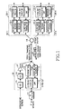
- Figs. 2A and 2B show the configuration of an Ethernet passive optical network (Ethernet-PON) for integrating broadcast and communication based on a TDM scheme, according to an embodiment of the present invention.
- Ethernet-PON Ethernet passive optical network
- the Ethernet-PON includes a single OLT, an optical splitter 216, and n ONTs.
- the n ONTs are assigned to n users, respectively. In other words, for each user, one ONT is connected to the network.
- the Ethernet-PON is configured as follows.
- the OLT 300 includes a broadcast/image channel selection switch 21, a broadcast/image time-slot multiplexer 22, a broadcast/image channel selection controller 23, an IP router 24, an E-PON OLT function processor 25, a synchronization controller 26, a frame multiplexer 27, an Ethernet time-slot matching buffer 28, an optical transmitter 29, an optical receiver 210, and a WDM coupler 211.
- the broadcast/image channel selection switch 21 performs a switching operation on MPEG (Motion Picture Experts Group) broadcast/image data.
- MPEG Motion Picture Experts Group
- the broadcast/image channel selection controller 23 receives respective channel selection information from the ONTs 400-1 to 400-16, and transfers a control signal to the broadcast/image channel selection switch 21 so as to allow the switch 21 to select their respective broadcast/image channels.
- the broadcast/image time-slot multiplexer 22 is connected to the broadcast/image channel selection switch 21 to multiplex the broadcast/image channels selected respectively by the subscribers into a single time-slot in a time division multiplexing (TDM) scheme.
- TDM time division multiplexing
- the IP router 24 routes communication data to an upper IP network or to the Ethernet-PON OLT function processor 25.
- the Ethernet-PON OLT function processor 25 performs Ethernet-PON OLT functions.
- the Ethernet time-slot matching buffer 28 stores communication data from the Ethernet-PON OLT function processor 25, which will be transmitted to the OLT, in order to match/couple it to the TDM (Time Division Multiplexed) broadcast/image signals.
- the frame multiplexer 27 multiplexes a broadcast/image signal from the broadcast/image time-slot multiplexer 22 and an Ethernet communication signal from the Ethernet time-slot matching buffer 28 into a single frame.
- the optical transmitter 29 transmits the frame-multiplexed signal after optically modulating it with a wavelength ⁇ DOWN .
- the optical receiver 210 receives an optical signal from the ONTs and converts it into an electrical signal.
- the WDM coupler 211 couples/splits transmission and reception wavelengths.
- each of the ONTs includes a WDM coupler 217, an optical transmitter 218, an optical transmitter 219, a frame/time-slot demultiplexer 220, an Ethernet-PON ONT function processor 221, and a broadcast/image adapter 222.
- the WDM coupler 217 couples and splits transmission and reception wavelengths.
- the optical transmitter 218 transmits upstream data to the OLT.
- the optical receiver 219 receives an optical signal of ⁇ DOWN from the OLT through the WDM coupler 217, and photoelectrically converts it.
- the frame/time-slot demultiplexer 220 separates the broadcast/image and Ethernet communication signals that have been multiplexed in a frame/time-slot multiplexing scheme.
- the Ethernet-PON ONT function processor 221 performs ONT functions.
- the broadcast/image adapter 222 recovers the separated broadcast/image signal into an original signal.
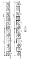
- Fig. 3 shows a first example of a frame and time-slots for Ethernet communication and broadcast/image signals, according to the present invention.
- a single frame 31 obtained by multiplexing broadcast/image signals and an Ethernet communication signal is divided into n time-slots 32-1, 32-2, ..., 32-n.
- the time-slots 32-1, 32-2, ..., 32-n are composed of broadcast/image sub-time-slots 32-1a, 32-2a, ..., 32-na and Ethernet sub-time-slots 32-1b, 32-2b, ..., 32-nb, respectively.
- the broadcast/image sub-time-slots 32-1a, 32-2a, ..., 32-na correspond to the subscribers, respectively.
- a broadcast/image sub-time-slot in an i-th time-slot is necessarily filled with only a broadcast/image signal selected by an i-th ONT, and it is left empty or filled with null data if there is no broadcast/image signal selected by the i-th ONT.
- communication data for every ONT may be positioned in the Ethernet sub-time-slots of all time-slots.
- a broadcast/image signal selected by the first ONT may be necessarily positioned in the broadcast/image sub-time-slot 32-1a of the first time-slot 32-1.
- An Ethernet communication signal of every ONT may be filled in the Ethernet sub-time-slot 32-1b of the first time-slot 32-1. The same is true for other time-slots 32-2, ..., 32-n.
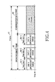
- Fig. 4 shows a second example of a frame and time-slots for Ethernet communication and broadcast/image signals, according to the present invention.
- a single frame 41 according to the present invention obtained by multiplexing broadcast/image signals and an Ethernet communication signal, is composed of a broadcast/image frame 42 and an Ethernet communication frame 43.
- the broadcast/image frame 42 is composed of time-slots 44-1, 44-2, ..., 44-n, fixedly assigned to the ONTs, respectively.
- Downstream communication (from the OLT to the ONTs) is performed in the following manner.
- MPEG digital broadcast and image channels are inputted to the broadcast/image channel selection switch 21.
- Each subscriber (or ONT) assigns a broadcast/image channel he or she desires to watch through a remote controller, and a signal thereof is transferred, as broadcast/image channel selection information 226, from the corresponding ONT to the broadcast/image channel selection controller 23 via the Ethernet-PON.
- the broadcast channel selection controller 23 provides a control signal 21-2 to the broadcast/image channel selection switch 21, and controls the switch 21 based on the broadcast/image channel selection information 226 to switch to digital broadcast/image signals 214-1, 214, ..., 214-n the subscribers (or ONTs) desire to watch, respectively.
- the broadcast/image signals 214-1, 214-2, ..., 214-n are selected by the first, second, ..., n-th ONTs, respectively.
- the switched broadcast/image signals are inputted to the broadcast/image time-slot multiplexer 22 to be formed according to the time-slot configuration defined in Fig. 3 .
- the frame and time-slot is configured as shown in Fig. 3 in the embodiments of the present invention. This frame and time-slot configuration is adopted only for illustrative purposes, and the present invention is not limited thereto, i.e., the present invention may also adopt the frame and time-slot configuration as shown in Fig. 4 .
- the broadcast/image time-slot multiplexer 22 multiplexes broadcast/image signals inputted at a predetermined speed of R [b/s] in a time-slot multiplexing scheme, as denoted by "51" in Fig. 5 , after converting it into a specific speed of 1.25 G/2k [b/s].
- This specific speed of 1.25 G/2k [b/s] is just an example, and the present invention is not limited thereto.
- the input speed of R [b/s] is 27M b/s in the case where the inputted signals are MPEG-TS streams.
- broadcast/image signals selected by the ONTs are positioned in the sub-time-slots uniquely assigned to the ONTs as defined in Fig. 3 , respectively.
- An Ethernet communication signal transmitted from an upper level IP network is subjected to Ethernet-PON function processes at the Ethernet-PON function processor 25 after passing through the IP router 24.
- the communication signal is then inputted to the Ethernet time-slot matching buffer 28 so as to satisfy the Ethernet frame and time-slot definition as shown in Fig. 3 .
- the Ethernet communication signal stored in the Ethernet time-slot matching buffer 28 is outputted only at the Ethernet sub-time-slots defined as shown in Fig. 3 , so as to have a format as denoted by "52" in Fig. 5 .
- the broadcast/image signal 51 outputted from the broadcast/image time-slot multiplexer 22 and the Ethernet communication signal 52 outputted from the Ethernet time-slot matching buffer 28 are frame-multiplexed by the frame multiplexer 27 as denoted by "53" in Fig. 5 .
- the frame-multiplexed broadcast/image and Ethernet communication signal is electro-optically converted into an optical signal having a wavelength ⁇ DOWN at the optical transmitter 29, and then transmitted to the ONTs via the WDM coupler 211 and the 1 x n optical splitter 216.
- the downstream optical signal inputted to the ONT is received and photoelectrically converted by the optical receiver 219 after passing through the WDM coupler 217.
- the converted signal is inputted to the frame and time-slot demultiplexer 220 to be separated into an Ethernet communication signal and a broadcast/image signal selected by the ONT.
- This demultiplexing operation is performed in the following manner. For example, in the first ONT, broadcast/image channels 62 and 63 selected by the first ONT are separated through a switching signal as denoted by "61" in Fig. 6 , since the channels 62 and 63 are positioned in the first time-slot of the frame.
- Ethernet communication signals 65-1 to 65-6 are separated through a switching signal as denoted by "64" in Fig. 6 .
- a synchronization problem occurring when separating the broadcast/image channel and communication data can be overcome by using a ranging-based synchronization, a function inherently provided by the Ethernet-PON.
- the separated communication signal 223 (denoted by "72" in Fig. 7 ) is transmitted, as downstream communication data 227, to a terminal device such as a computer after passing through the ONT function processor 221.
- the separated broadcast/image channel 224 (denoted by "71" in Fig. 7 ) is converted into the original speed of R [b/s] (27 Mb/s in the case of MPEG-TS stream signals), which is then transferred, as a digital broadcast/image signal 228, to an MPEG decoder, etc.
- upstream communication (from the ONTs to the OLT) is performed in the following manner.
- Each subscriber produces broadcast/image channel selection data or information 226 for watching a broadcast/image channel and IP communication data 225 through a computer, etc.
- the produced data is optically modulated into an optical signal having a wavelength ⁇ UP at the optical transmitter 218.
- the converted optical signal is transmitted to the OLT via the WDM coupler 217 and the optical splitter 216.
- Upstream data signals transmitted from the ONTs are photoelectrically modulated at the optical receiver 210 after passing through the WDM coupler 211 in the OLT.
- the modulated upstream signal is transferred to the Ethernet-PON OLT function processor 25.
- the broadcast/image channel selection information 21-3 is transferred from the Ethernet-PON OLT function processor 25 to the broadcast/image channel selection controller 23, and the IP communication data is transferred to an upper level IP network through the IP router 24.
- Fig. 8 shows the configuration of an example of a hybrid Ethernet-PON, including a plurality of Ethernet-PONs, for integrating broadcast and communication based on a TDM scheme, according to the present invention.
- the hybrid Ethernet-PON for integrating broadcast and communication includes L OLTs and L x n ONTs, which operates in the following manner.
- a digital broadcast signal transmitted from an SO (Service Operator) or DMC (Digital Medical Center) 81 is separated into N MPEG digital broadcast channels at a digital broadcast channel separator 83.
- Each separated MPEG digital broadcast channel is split into L signals at a corresponding one of N splitters 87-1 to 87-N, which are transferred to L Ethernet-PON OLTs 89-1, 89-2, ..., 89-L, respectively.
- Digital image data transmitted from a digital image source 82 is separated into M MPEG digital image channels at a digital image channel separator 84. Each separated channel is split into L signals at a corresponding one of M splitters 88-1 to 88-M, which are transferred to the L Ethernet-PON OLTs 89-1, 89-2, ..., 89-L, respectively.
- IP network 85 Communication data transmitted from an IP network 85 is inputted to an IP router 86, through which it is routed to the L OLTs 89-1 to 89-L.
- the digital broadcast/image and communication data is transmitted to the ONTs 812-1 to 812-16 via an optical cable 810 and an optical splitter 811, as described above in detail with reference to Figs. 2A and 2B .
- Figs 9A and 9B show the configuration of an Ethernet-PON employing an optical receiver and an optical transmitter separately provided for broadcast/image signals, according to another embodiment of the present invention.
- the Ethernet-PON in this embodiment employs the optical receiver and transmitter separately provided for broadcast/image signals in order to secure a wide broadcast/image bandwidth.
- This embodiment is different from the embodiment of Figs. 2A and 2B in that an Ethernet communication signal and broadcast/image signals are separately subjected to electro-optical conversion at an OLT so as to be transmitted, and time division multiplexing is thus required only for the broadcast/image signals. There is also no need for this embodiment to perform frame multiplexing, etc.
- upstream and downstream Ethernet communication signals are all subjected to the operation of an Ethernet-PON ONT function processor 99 without being demultiplexed, whereas broadcast/image signals are subjected to time division demultiplexing and broadcast/image adaptation through a time division demultiplexer & broadcast/image adapter 98.
- a broadcast/image frame 1000-1 or 1000-2 as shown in Fig. 10 is composed of time-slots 1000-1-1 to 1000-1-16 or 1000-2-1 to 1000-2-16, respectively, for broadcast/image signals of the ONTs.
- the time-slots 1000-1-1 to 1000-1-16 or 1000-2-1 to 1000-2-16 are each composed of a plurality of sub-time-slots (two sub-time-slots in this embodiment) 1000-1-1a/b to 1000-1-16a/b or 1000-2-1a/b to 1000-2-16a/b for accommodating broadcast/image signals.
- the i-th time-slots are assigned to the i-th ONT, and only broadcast/image signals selected by the i-th ONT are necessarily positioned in the i-th time-slots. At least one sub-time-slot of the i-th time-slot is left empty or filled with null data if there is only one or no broadcast/image channel selected by the i-th ONT.
- the broadcast/image signal speed may be determined based on the number of broadcast/image signals required to be accommodated, etc.
- broadcast/image signals selected by the first ONT are necessarily positioned in the broadcast/image sub-time-slots 1000-1-1a/b or 1000-2-1a/b of the first time-slot 1000-1-1 or 1000-2-1.
- broadcast/image signals selected by the sixteenth ONT are necessarily positioned in the broadcast/image sub-time-slots 1000-1-16a/b or 1000-2-16a/b of the sixteenth time-slot 1000-1-16 or 1000-2-16. The same is true for other time-slots.
- Fig. 11 illustrates how desired broadcast/image time-slots are separated from time-division-multiplexed frames, according to said another embodiment of the present invention shown in Figs. 9A and 9B .
- time-slots assigned to the corresponding ONT may be selected through a switching signal as denoted by "1001".
- Fig. 12 illustrates a broadcast/image signal separated from the signal shown in Fig. 11 through the switching signal 1001.
- Broadcast/image channels corresponding respectively to the subscribers, selected at a broadcast/image channel selection switch 21 are inputted to a broadcast/image time division multiplexer 91.
- the selected signals are multiplexed in a TDM scheme according to the time-slot location definition as shown in Fig. 10 .
- the broadcast/image signal speed is R [b/s]
- the TDM (Time Division multiplexed) broadcast/image signal speed is K [b/s].
- the TDM broadcast/image signal is optically modulated and transmitted to the ONTs.
- the transmitted signal is received by an optical receiver 97 in an ONT.
- the ONT must select a broadcast/image channel selected by it, since the received broadcast/image signal includes all broadcast/image channels selected by all the ONTs.
- a broadcast/image channel selected by the first ONT corresponding to the time-slots 1000-1-1 and 1000-2-1, is separated from broadcast/image data received by the first ONT, as shown in Fig. 12 , through the switching signal 2000 of Fig. 11 at a time division demultiplexer & broadcast/image adapter 98 in the first ONT, since the received broadcast/image data includes all the broadcast/image channels selected by all the ONTs, as shown in Fig. 11 .
- the separated broadcast/image signals are converted into an original data speed of R [b/s] at a broadcast/image adapter portion in the time division demultiplexer & broadcast/image adapter 98.
- the converted signals are transmitted to an MPEG decoder, etc.
- an Ethernet-PON for integrating broadcast and communication based on a TDM scheme has the following advantages. Since broadcast channels desired by users are selected at an OLT to be transmitted to ONTs, it is possible for the ONTs to use a low cost, low spec optical receiver for receiving broadcast signals, instead of an EDFA for a large amount of broadcast signals.
- broadcast information is transmitted through a communication data line in the Ethernet-PON, thereby enabling bi-directional broadcasting functions.
Landscapes
- Engineering & Computer Science (AREA)
- Computer Networks & Wireless Communication (AREA)
- Signal Processing (AREA)
- Small-Scale Networks (AREA)
- Optical Communication System (AREA)
Applications Claiming Priority (2)
| Application Number | Priority Date | Filing Date | Title |
|---|---|---|---|
| KR1020030067087A KR100594075B1 (ko) | 2003-09-26 | 2003-09-26 | 시간 분할 다중화를 이용한 방송 통신 융합을 위한 이더넷수동형 광 가입자 망 |
| KR2003067087 | 2003-09-26 |
Publications (3)
| Publication Number | Publication Date |
|---|---|
| EP1519616A2 EP1519616A2 (en) | 2005-03-30 |
| EP1519616A3 EP1519616A3 (en) | 2007-10-24 |
| EP1519616B1 true EP1519616B1 (en) | 2013-09-18 |
Family
ID=34192276
Family Applications (1)
| Application Number | Title | Priority Date | Filing Date |
|---|---|---|---|
| EP04013477.7A Expired - Lifetime EP1519616B1 (en) | 2003-09-26 | 2004-06-08 | Ethernet passive optical network integrating image broadcast and data communication based on time division multiplexing |
Country Status (5)
| Country | Link |
|---|---|
| US (1) | US7382982B2 (zh) |
| EP (1) | EP1519616B1 (zh) |
| JP (1) | JP4012532B2 (zh) |
| KR (1) | KR100594075B1 (zh) |
| CN (1) | CN1330142C (zh) |
Families Citing this family (36)
| Publication number | Priority date | Publication date | Assignee | Title |
|---|---|---|---|---|
| EP1271825A1 (en) * | 2001-06-25 | 2003-01-02 | Lucent Technologies Inc. | Method and system for multiplexed optical information transport |
| KR100582550B1 (ko) * | 2004-02-11 | 2006-05-22 | 한국전자통신연구원 | 수동형 광 네트워크에서의 방송 데이터 서비스 시스템 및서비스 방법 |
| KR100640475B1 (ko) * | 2004-07-22 | 2006-10-30 | 삼성전자주식회사 | 방송 통신 융합 시스템에 사용되는 통신 방송 다중화기 및역다중화기 |
| US20060171714A1 (en) * | 2005-02-02 | 2006-08-03 | Calix Networks, Inc. | Electrically shared passive optical network |
| KR100703379B1 (ko) * | 2005-02-16 | 2007-04-03 | 삼성전자주식회사 | 무선 송수신 장치 |
| DE102005026173B4 (de) * | 2005-06-06 | 2012-11-15 | Adva Ag Optical Networking | Verfahren und Zeitmultiplex-/Demultiplexeinheit zur Datenübertragung im Zeitmultiplex, insbesondere zur bandbreiten-optimierten Datenübertragung von IP Verkehr mit Broadcast- und Multicast-Anteilen in einem WDM-System |
| JP4687332B2 (ja) * | 2005-08-25 | 2011-05-25 | 日本電気株式会社 | 光アクセスネットワークのセンタ側装置および光アクセスネットワークのデータ信号送出方法 |
| US8600238B2 (en) * | 2005-11-01 | 2013-12-03 | Technology Advancement Group, Inc. | Method and system for bi-directional communication over a single optical fiber |
| US7840138B2 (en) * | 2005-11-01 | 2010-11-23 | Technology Advancement Group, Inc. | Method and system for bi-directional communication over a single optical fiber |
| JP4634290B2 (ja) * | 2005-11-29 | 2011-02-16 | 富士通株式会社 | 伝送装置 |
| KR100723874B1 (ko) * | 2005-12-09 | 2007-05-31 | 한국전자통신연구원 | 방송 서비스를 위한 tdma pon olt 시스템 |
| CN1863013B (zh) * | 2005-12-28 | 2010-05-05 | 华为技术有限公司 | 无源光网络中的网络终端装置及其数据处理方法 |
| WO2007082478A1 (fr) * | 2006-01-18 | 2007-07-26 | Huawei Technologies Co., Ltd. | Procédé permettant d'établir une correspondance entre un flux de service et un canal de transmission de service, système et terminateur de réseau optique associés |
| US20070211755A1 (en) * | 2006-03-10 | 2007-09-13 | Siemens Aktiengesellschaft | Communications network and method of increasing bandwidth in a cable network |
| US7561801B2 (en) * | 2006-03-31 | 2009-07-14 | Applied Micro Circuits Corporation | Optical transceiver with electrical ring distribution interface |
| CN1976477B (zh) * | 2006-12-11 | 2011-12-28 | 中兴通讯股份有限公司 | 一种移动多媒体广播数据的传输方法 |
| US7970281B2 (en) * | 2007-01-26 | 2011-06-28 | Fujitsu Limited | System and method for managing different transmission architectures in a passive optical network |
| JP4823110B2 (ja) * | 2007-03-15 | 2011-11-24 | 富士通株式会社 | 受動光網システムおよび受動光網におけるデータ伝送方法 |
| US7894362B2 (en) * | 2007-04-30 | 2011-02-22 | Futurewei Technologies, Inc. | Passive optical network topology estimation |
| US8059962B2 (en) * | 2007-05-30 | 2011-11-15 | Futurewei Technologies, Inc. | Interleaving for 10G GPON |
| US20090052901A1 (en) * | 2007-08-20 | 2009-02-26 | Knology, Inc. | Hybrid fiber coax (hfc) circuit |
| US8086104B2 (en) * | 2008-02-15 | 2011-12-27 | Alcatel Lucent | System, method and computer readable medium for providing dual rate transmission on a gigabit passive optical network |
| CN102026047A (zh) * | 2009-09-10 | 2011-04-20 | 华为技术有限公司 | 复位信号和速率指示信号的传送方法、装置及系统 |
| CN102546017A (zh) * | 2010-12-14 | 2012-07-04 | 大屯有线电视股份有限公司 | 分时多工光纤网络系统及其方法 |
| WO2013185111A2 (en) | 2012-06-07 | 2013-12-12 | Apple Inc. | Methods and apparatus for synchronization among integrated circuits within a wireless network |
| US9979505B2 (en) * | 2012-09-10 | 2018-05-22 | Tellabs Enterprise, Inc. | Delivery of GPON technology |
| US10102175B2 (en) * | 2013-03-15 | 2018-10-16 | Apple Inc. | Methods and apparatus for multi-drop digital bus |
| US9602311B2 (en) * | 2014-02-06 | 2017-03-21 | The Board Of Trustees Of The Leland Stanford Junior University | Dual-mode network |
| US9811991B2 (en) * | 2014-06-27 | 2017-11-07 | Harman International Industries, Incorporated | Do-not-disturb system and apparatus |
| US10250353B2 (en) | 2014-11-10 | 2019-04-02 | Perfectvision Manufacturing, Inc. | Electromagnetic signal transport and distribution systems |
| US9806844B2 (en) * | 2014-11-10 | 2017-10-31 | Perfectvision Manufacturing, Inc. | Electromagnetic signal transport and distribution system |
| US10085224B2 (en) | 2014-11-19 | 2018-09-25 | Apple Inc. | Methods and apparatus for synchronization of media playback within a wireless network |
| CN104486695B (zh) * | 2014-12-03 | 2018-01-12 | 中国航空工业集团公司第六三一研究所 | 一种光波分复用机载全光交换网络结构 |
| US11350061B1 (en) * | 2021-11-11 | 2022-05-31 | Frontier Communications Holdings, Llc | Systems and methods for collecting information regarding optical connections in a fiber distribution hub of a passive optical network |
| US11391894B1 (en) | 2021-11-11 | 2022-07-19 | Frontier Communications Holdings, Llc | Passive optical couplers having passive optical activity indicators and methods of operating the same |
| US11356177B1 (en) | 2021-11-11 | 2022-06-07 | Frontier Communications Holdings, Llc | Systems and methods for mapping optical connections in a fiber distribution hub of a passive optical network |
Family Cites Families (25)
| Publication number | Priority date | Publication date | Assignee | Title |
|---|---|---|---|---|
| DE3045875A1 (de) * | 1980-12-05 | 1982-09-09 | Licentia Patent-Verwaltungs-Gmbh, 6000 Frankfurt | Dienstintegriertes, digitales uebertragungssystem |
| US4994909A (en) * | 1989-05-04 | 1991-02-19 | Northern Telecom Limited | Video signal distribution system |
| US5150247A (en) * | 1989-10-30 | 1992-09-22 | Broadband Technologies, Inc. | Fiber optic telecommunication system employing continuous downlink, burst uplink transmission format with preset uplink guard band |
| US5576874A (en) * | 1991-07-31 | 1996-11-19 | Alcatel Network Systems, Inc. | Optical distribution shelf for a remote terminal of an optical fiber telecommunications network |
| DE4417771A1 (de) * | 1994-05-20 | 1995-11-23 | Siemens Ag | Optisches TDM/TDMA-System mit erhöhtem Reichweitenbereich |
| US5680234A (en) * | 1994-10-20 | 1997-10-21 | Lucent Technologies Inc. | Passive optical network with bi-directional optical spectral slicing and loop-back |
| NZ331915A (en) * | 1996-03-18 | 1999-05-28 | Gen Instrument Corp | Dynamic bandwidth allocation for a communication network |
| GB9704587D0 (en) * | 1997-03-05 | 1997-04-23 | Fujitsu Ltd | Wavelength-division multiplexing in passive optical networks |
| DE19727547A1 (de) * | 1997-06-28 | 1999-01-07 | Bosch Gmbh Robert | Verfahren für eine Signalübertragung in einem Netz |
| US6684031B1 (en) * | 1998-06-18 | 2004-01-27 | Lucent Technologies Inc. | Ethernet fiber access communications system |
| CN1244751A (zh) | 1998-08-06 | 2000-02-16 | 深圳市华为技术有限公司 | 无源光纤网络系统 |
| US6796555B1 (en) * | 1999-07-19 | 2004-09-28 | Lucent Technologies Inc. | Centralized video controller for controlling distribution of video signals |
| US6498667B1 (en) * | 1999-09-10 | 2002-12-24 | Quantum Bridge Communications, Inc. | Method and system for packet transmission over passive optical network |
| US6778550B1 (en) * | 2000-02-29 | 2004-08-17 | Lucent Technologies Inc. | Method and apparatus for TDM/TDMA communications |
| US7031343B1 (en) * | 2000-11-17 | 2006-04-18 | Alloptic, Inc. | Point-to-multipoint passive optical network that utilizes variable-length packets |
| US7212540B2 (en) * | 2001-04-05 | 2007-05-01 | Nortel Networks Limited | Time slot scheduling for shared-medium communications networks |
| JP3636679B2 (ja) | 2001-07-03 | 2005-04-06 | 松下電器産業株式会社 | コンテンツ配信方法および端末管理サーバ装置 |
| US20030007724A1 (en) * | 2001-07-05 | 2003-01-09 | Broadcom Corporation | System, method, and computer program product for optimizing video service in ethernet-based fiber optic TDMA networks |
| US6804256B2 (en) * | 2001-07-24 | 2004-10-12 | Glory Telecommunications Co., Ltd. | Automatic bandwidth adjustment in a passive optical network |
| JP2003092583A (ja) | 2001-09-19 | 2003-03-28 | Fujitsu Ltd | 通信帯域を有効利用できる受動光ネットワークシステム |
| JP4776835B2 (ja) | 2001-09-20 | 2011-09-21 | シンクレイヤ株式会社 | 光ファイバネットワークシステムの伝送方式 |
| US6697374B1 (en) * | 2001-12-05 | 2004-02-24 | Flexlight Networks | Optical network communication system |
| KR100606102B1 (ko) * | 2002-08-03 | 2006-07-28 | 삼성전자주식회사 | 방송/통신 통합형 수동 광네트웍 시스템 |
| US7221685B2 (en) * | 2002-12-13 | 2007-05-22 | Sbc Properties, L.P. | Method and system relating to bandwidth utilization |
| JP3880994B2 (ja) * | 2003-03-04 | 2007-02-14 | 富士通株式会社 | コンテンツ情報の配信方法並びに配信システムおよびそのセンタ局 |
-
2003
- 2003-09-26 KR KR1020030067087A patent/KR100594075B1/ko not_active IP Right Cessation
-
2004
- 2004-03-29 US US10/811,600 patent/US7382982B2/en not_active Expired - Fee Related
- 2004-04-26 CN CNB2004100369949A patent/CN1330142C/zh not_active Expired - Fee Related
- 2004-06-08 EP EP04013477.7A patent/EP1519616B1/en not_active Expired - Lifetime
- 2004-09-24 JP JP2004276807A patent/JP4012532B2/ja not_active Expired - Fee Related
Also Published As
| Publication number | Publication date |
|---|---|
| CN1601986A (zh) | 2005-03-30 |
| US7382982B2 (en) | 2008-06-03 |
| JP2005110247A (ja) | 2005-04-21 |
| EP1519616A2 (en) | 2005-03-30 |
| KR100594075B1 (ko) | 2006-06-30 |
| EP1519616A3 (en) | 2007-10-24 |
| US20050069318A1 (en) | 2005-03-31 |
| JP4012532B2 (ja) | 2007-11-21 |
| CN1330142C (zh) | 2007-08-01 |
| KR20050030511A (ko) | 2005-03-30 |
Similar Documents
| Publication | Publication Date | Title |
|---|---|---|
| EP1519616B1 (en) | Ethernet passive optical network integrating image broadcast and data communication based on time division multiplexing | |
| US7366415B2 (en) | Wavelength division multiplexing-passive optical network capable of integrating broadcast and communication services | |
| KR100557144B1 (ko) | 시간 분할 다중화를 이용한 방송 통신 융합을 위한 이더넷수동형 광 가입자 망 | |
| KR101879850B1 (ko) | 확장된 도달거리 및 용량을 갖는 twdm 패시브 네트워크 | |
| EP1619815A2 (en) | Broadcast multiplexer and demultiplexer in an integrated communication system | |
| US7684706B2 (en) | System and method for traffic distribution in an optical network | |
| US8548329B2 (en) | Apparatus and method for relaying in gigabit passive optical network | |
| KR100605855B1 (ko) | 방송 스위칭을 통한 방송 통신 융합 ftth망 | |
| EP1387511B1 (en) | Broadcast/communication unified passive optical network system | |
| US20020196491A1 (en) | Passive optical network employing coarse wavelength division multiplexing and related methods | |
| EP2656527B1 (en) | A passive optical network arrangement and method | |
| KR100506201B1 (ko) | 방송 통신 융합을 위한 이더넷 수동형 광 가입자 망 | |
| KR20030076762A (ko) | 파장분할다중 방식의 수동형 광네트웍 시스템 | |
| KR20110053973A (ko) | Wdm pon rf/비디오 브로드캐스트 오버레이 | |
| EP1511202B1 (en) | Optical subscriber network system | |
| WO2007083384A1 (ja) | 受動光網システムにおける片方向伝送信号分配方法、局側装置及び加入者宅側装置 |
Legal Events
| Date | Code | Title | Description |
|---|---|---|---|
| PUAI | Public reference made under article 153(3) epc to a published international application that has entered the european phase |
Free format text: ORIGINAL CODE: 0009012 |
|
| 17P | Request for examination filed |
Effective date: 20040608 |
|
| AK | Designated contracting states |
Kind code of ref document: A2 Designated state(s): AT BE BG CH CY CZ DE DK EE ES FI FR GB GR HU IE IT LI LU MC NL PL PT RO SE SI SK TR |
|
| AX | Request for extension of the european patent |
Extension state: AL HR LT LV MK |
|
| PUAL | Search report despatched |
Free format text: ORIGINAL CODE: 0009013 |
|
| AK | Designated contracting states |
Kind code of ref document: A3 Designated state(s): AT BE BG CH CY CZ DE DK EE ES FI FR GB GR HU IE IT LI LU MC NL PL PT RO SE SI SK TR |
|
| AX | Request for extension of the european patent |
Extension state: AL HR LT LV MK |
|
| AKX | Designation fees paid |
Designated state(s): DE FR GB |
|
| 17Q | First examination report despatched |
Effective date: 20110502 |
|
| RAP1 | Party data changed (applicant data changed or rights of an application transferred) |
Owner name: SAMSUNG ELECTRONICS CO., LTD. |
|
| GRAP | Despatch of communication of intention to grant a patent |
Free format text: ORIGINAL CODE: EPIDOSNIGR1 |
|
| INTG | Intention to grant announced |
Effective date: 20130404 |
|
| GRAS | Grant fee paid |
Free format text: ORIGINAL CODE: EPIDOSNIGR3 |
|
| GRAA | (expected) grant |
Free format text: ORIGINAL CODE: 0009210 |
|
| AK | Designated contracting states |
Kind code of ref document: B1 Designated state(s): DE FR GB |
|
| REG | Reference to a national code |
Ref country code: GB Ref legal event code: FG4D |
|
| REG | Reference to a national code |
Ref country code: DE Ref legal event code: R096 Ref document number: 602004043348 Country of ref document: DE Effective date: 20131114 |
|
| REG | Reference to a national code |
Ref country code: DE Ref legal event code: R097 Ref document number: 602004043348 Country of ref document: DE |
|
| PLBE | No opposition filed within time limit |
Free format text: ORIGINAL CODE: 0009261 |
|
| STAA | Information on the status of an ep patent application or granted ep patent |
Free format text: STATUS: NO OPPOSITION FILED WITHIN TIME LIMIT |
|
| 26N | No opposition filed |
Effective date: 20140619 |
|
| REG | Reference to a national code |
Ref country code: DE Ref legal event code: R097 Ref document number: 602004043348 Country of ref document: DE Effective date: 20140619 |
|
| REG | Reference to a national code |
Ref country code: FR Ref legal event code: ST Effective date: 20150227 |
|
| PG25 | Lapsed in a contracting state [announced via postgrant information from national office to epo] |
Ref country code: FR Free format text: LAPSE BECAUSE OF NON-PAYMENT OF DUE FEES Effective date: 20140630 |
|
| PGFP | Annual fee paid to national office [announced via postgrant information from national office to epo] |
Ref country code: GB Payment date: 20170522 Year of fee payment: 14 Ref country code: DE Payment date: 20170522 Year of fee payment: 14 |
|
| REG | Reference to a national code |
Ref country code: DE Ref legal event code: R119 Ref document number: 602004043348 Country of ref document: DE |
|
| GBPC | Gb: european patent ceased through non-payment of renewal fee |
Effective date: 20180608 |
|
| PG25 | Lapsed in a contracting state [announced via postgrant information from national office to epo] |
Ref country code: GB Free format text: LAPSE BECAUSE OF NON-PAYMENT OF DUE FEES Effective date: 20180608 Ref country code: DE Free format text: LAPSE BECAUSE OF NON-PAYMENT OF DUE FEES Effective date: 20190101 |