EP1519391A2 - Transformateur encapsulé en résine - Google Patents
Transformateur encapsulé en résine Download PDFInfo
- Publication number
- EP1519391A2 EP1519391A2 EP20040090341 EP04090341A EP1519391A2 EP 1519391 A2 EP1519391 A2 EP 1519391A2 EP 20040090341 EP20040090341 EP 20040090341 EP 04090341 A EP04090341 A EP 04090341A EP 1519391 A2 EP1519391 A2 EP 1519391A2
- Authority
- EP
- European Patent Office
- Prior art keywords
- taps
- winding
- regions
- winding parts
- transformer according
- Prior art date
- Legal status (The legal status is an assumption and is not a legal conclusion. Google has not performed a legal analysis and makes no representation as to the accuracy of the status listed.)
- Granted
Links
- 239000011347 resin Substances 0.000 title claims abstract description 8
- 229920005989 resin Polymers 0.000 title claims abstract description 8
- 238000004804 winding Methods 0.000 claims abstract description 108
- 238000001816 cooling Methods 0.000 claims description 6
- 238000010079 rubber tapping Methods 0.000 claims description 3
- 239000004020 conductor Substances 0.000 description 5
- 238000004519 manufacturing process Methods 0.000 description 2
- 230000001419 dependent effect Effects 0.000 description 1
- 238000011161 development Methods 0.000 description 1
- 230000018109 developmental process Effects 0.000 description 1
- 238000010586 diagram Methods 0.000 description 1
- 230000000694 effects Effects 0.000 description 1
Images

Classifications
-
- H—ELECTRICITY
- H01—ELECTRIC ELEMENTS
- H01F—MAGNETS; INDUCTANCES; TRANSFORMERS; SELECTION OF MATERIALS FOR THEIR MAGNETIC PROPERTIES
- H01F27/00—Details of transformers or inductances, in general
- H01F27/28—Coils; Windings; Conductive connections
- H01F27/29—Terminals; Tapping arrangements for signal inductances
-
- H—ELECTRICITY
- H01—ELECTRIC ELEMENTS
- H01F—MAGNETS; INDUCTANCES; TRANSFORMERS; SELECTION OF MATERIALS FOR THEIR MAGNETIC PROPERTIES
- H01F27/00—Details of transformers or inductances, in general
- H01F27/28—Coils; Windings; Conductive connections
- H01F27/32—Insulating of coils, windings, or parts thereof
- H01F27/327—Encapsulating or impregnating
Definitions
- the invention relates to a cast resin transformer according to the preamble of claim 1.
- From DE 198 09 572 C2 is a cast resin transformer with a low voltage winding and with a coaxially surrounding this High-voltage winding with an axial cooling channel known between two winding parts.
- the two winding parts are connected in parallel and exist in each case from two axial part windings, each with several coils contain.
- Each winding part consists of a radially inner Partial winding and a radially outer part of the winding, the arranged axially one behind the other and electrically connected in series are. Because the exact adjustment of the upper voltage only via winding taps on the radially outer part windings can take place, this voltage setting to the two winding parts at different voltage values instead of. Therefore, it must be done separately for them, so that for each winding part a separate tap changer is required.
- the areas provided with the taps are the two winding parts by a partial winding with each formed a number of coils and these partial windings coaxial with those not provided with the taps Regions of the two winding parts and in the axial direction arranged one behind the other.
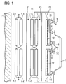
- Fig. 1 shows the extending in the axial direction right outer edge 1 of a core of, for example, three core legs provided cast resin transformer.
- the cores are each equipped with the same winding arrangement. Coaxial are guided around the core on the radially inner side a low voltage winding and on the radially outer side a high voltage winding.
- the undervoltage winding and the high voltage winding are in the radial direction at a distance arranged one another and thus form an axial Cooling channel 2.
- the low voltage winding consists of two in axial Direction extending, electrically connected in parallel Winding parts, each consisting of two in the axial direction successive partial windings 3.1, 3.2 and 4.1, 4.2 are formed.
- the partial winding 3.1 of the first Winding parts spatially within the partial winding 4.1 of second winding part and the part winding 3.2 of the first Winding parts spatially outside of the partial winding 4.2 of second winding part arranged.
- the high-voltage winding also has two in axial Direction extending, electrically connected in parallel Winding on, each two in the axial direction one behind the other lying partial windings 5.1, 5.2 and 6.1, 6.2 contain. Their spatial assignment is the same as with the low-voltage winding such that the two partial windings 5.1 and 5.2 or 6.1 and 6.2 of a winding part axially one behind the other lie and that the partial winding 5.1 of the first Winding parts concentric of the partial winding 6.1 of second winding part and the partial winding 6.2 of the second Winding parts concentric of the partial winding 5.2 of the first Winding parts are surrounded.
- the winding parts contain the high-voltage winding additionally in each case a third sub-winding 5.3 or 6.3.
- These partial windings 5.3 and 6.3 are on the one hand with the other partial windings 5.1 and 5.2 or 6.1 and 6.2 their winding part connected in series, on the other hand at their respective two ends by conductors 7 and 8 directly connected together so that they are directly parallel to each other are switched.
- the connections 9 and 10 of the high voltage winding are on the one hand with one the upper ends of the Partial windings 5.1 and 6.1 connecting conductors 11 and on the other connected to the conductor 8.
- the partial windings 5.3 and 6.3 are each, as shown in FIG. 1 shows, from several, in the example shown ten, one behind the other each coil 12 is shown in FIG. 2 provided with a tap 13; however, the coils can 12 each have a plurality of taps 13.
- the taps 13 are opposite to the leads shown in Fig. 1 to sub-windings 5.3 and 6.3 in their circumferential direction Offset 180 ° and therefore not shown in Fig. 1.
- the partial windings 5.3 and 6.3 are identical to each other, so that each coil 12 or tapping 13 of the partial winding 5.3 a coil 12 or tapping 13 of the partial winding 6.3 corresponds, which is at the same potential.
- the taps 13 are connected to terminals of a switching strip 14. These contains internal connection lines 15 such that the both lying at the same potential taps 13 of the partial windings 5.3 and 6.3 are connected to each other.
- Each with two taps at the same potential 13 connected connection line 15 is to an outer Connection of the switching strip 14 out, which in turn with a Connection of a tap changer 16 is connected.
- the partial windings are 5.3 and 6.3 also concentric with the core and the partial windings 6.1 and 5.2 arranged surrounding, wherein in axial Direction behind each other.
- the two conductors 7 and 8 connect each the opposite and the one another facing ends of the partial windings 5.3 and 6.3 on Terminal supports 17, 18, 19 and 20.
- An auxiliary support 21 is used for fixing a conductor 22 between the terminal 9 and the leader 11.
Landscapes
- Engineering & Computer Science (AREA)
- Power Engineering (AREA)
- Coils Of Transformers For General Uses (AREA)
- Ac-Ac Conversion (AREA)
- Coils Or Transformers For Communication (AREA)
Applications Claiming Priority (2)
| Application Number | Priority Date | Filing Date | Title |
|---|---|---|---|
| DE2003145659 DE10345659B4 (de) | 2003-09-25 | 2003-09-25 | Gießharz-Transformator |
| DE10345659 | 2003-09-25 |
Publications (3)
| Publication Number | Publication Date |
|---|---|
| EP1519391A2 true EP1519391A2 (fr) | 2005-03-30 |
| EP1519391A3 EP1519391A3 (fr) | 2006-03-01 |
| EP1519391B1 EP1519391B1 (fr) | 2016-11-02 |
Family
ID=34178036
Family Applications (1)
| Application Number | Title | Priority Date | Filing Date |
|---|---|---|---|
| EP04090341.1A Expired - Lifetime EP1519391B1 (fr) | 2003-09-25 | 2004-09-06 | Transformateur encapsulé en résine |
Country Status (2)
| Country | Link |
|---|---|
| EP (1) | EP1519391B1 (fr) |
| DE (1) | DE10345659B4 (fr) |
Citations (2)
| Publication number | Priority date | Publication date | Assignee | Title |
|---|---|---|---|---|
| DE263421C (fr) | 1911-07-04 | 1913-09-05 | ||
| DE19809572C2 (de) | 1998-03-05 | 2000-06-21 | Siemens Ag | Gießharz-Transformator |
Family Cites Families (3)
| Publication number | Priority date | Publication date | Assignee | Title |
|---|---|---|---|---|
| EP0097367A1 (fr) * | 1982-06-23 | 1984-01-04 | Hitachi, Ltd. | Transformateur avec bobines partagées |
| DE3338149A1 (de) * | 1983-10-20 | 1985-05-02 | Transformatoren Union Ag, 7000 Stuttgart | Schaltungsanordnung fuer leistungsgrosstransformatoren |
| DE3936937A1 (de) * | 1989-11-06 | 1991-05-08 | Siemens Ag | Wicklungsanordnung fuer giessharztransformatoren |
-
2003
- 2003-09-25 DE DE2003145659 patent/DE10345659B4/de not_active Expired - Fee Related
-
2004
- 2004-09-06 EP EP04090341.1A patent/EP1519391B1/fr not_active Expired - Lifetime
Patent Citations (2)
| Publication number | Priority date | Publication date | Assignee | Title |
|---|---|---|---|---|
| DE263421C (fr) | 1911-07-04 | 1913-09-05 | ||
| DE19809572C2 (de) | 1998-03-05 | 2000-06-21 | Siemens Ag | Gießharz-Transformator |
Also Published As
| Publication number | Publication date |
|---|---|
| EP1519391A3 (fr) | 2006-03-01 |
| DE10345659A1 (de) | 2005-04-28 |
| EP1519391B1 (fr) | 2016-11-02 |
| DE10345659B4 (de) | 2005-11-10 |
Similar Documents
| Publication | Publication Date | Title |
|---|---|---|
| EP0102513A1 (fr) | Transformateur à sec avec enroulements fondus dans une résine de coulée | |
| DE3718383A1 (de) | Hochfrequenz-leistungsuebertrager | |
| DE19809572C2 (de) | Gießharz-Transformator | |
| DE102014100949A1 (de) | Laststufenschalter nach dem Reaktorschaltprinzip | |
| WO2012159691A1 (fr) | Enroulement auxiliaire de transformateur | |
| DE2112489A1 (de) | Stromwandleraufbau | |
| DE102015226097B3 (de) | Wicklungsanordnung, Transformator und Spule | |
| EP0561839B1 (fr) | Transformateur h.t. pour postes recepteurs de television | |
| EP1519391B1 (fr) | Transformateur encapsulé en résine | |
| WO2009146835A2 (fr) | Transformateur | |
| DE2301519A1 (de) | Netztransformator | |
| DE102004008961B4 (de) | Spulenkörper für geschlossenen magnetischen Kern und daraus hergestellte Entstördrossel | |
| EP2780918B1 (fr) | Composant inductif | |
| DE3126972C2 (de) | Schaltungsanordnung für die Wicklungen eines Doppelstocktransformators | |
| DE2651734A1 (de) | Spulenkoerper | |
| DE19901172C2 (de) | Hochspannungstransformator und Verfahren zum Herstellen des Hochspannungstransformators | |
| DE2904746C3 (de) | Wicklung für einen luftgekühlten Trockentransformator | |
| WO1995011514A1 (fr) | Transformateur de puissance | |
| EP0166952B1 (fr) | Transformateur à forte intensité avec ajustement indirect de tension par circuit intermédiaire | |
| DE950310C (de) | Drosselspule | |
| DE10353529A1 (de) | Transformator mit Spulenmodulen und Verfahren zur Herstellung eines solchen Transformators | |
| EP0605412A1 (fr) | Procede de fabrication d'enroulements de bobines. | |
| DE1282172B (de) | Mehrgaengige oder aus aufeinanderfolgenden Windungsgruppen bestehende Anzapfwicklung fuer Stufentransformatoren | |
| EP0312973A1 (fr) | Elément de bobinage pour transformateur et dispositifs semblables | |
| EP0166951A1 (fr) | Transformateur avec une traversée à forte intensité |
Legal Events
| Date | Code | Title | Description |
|---|---|---|---|
| PUAI | Public reference made under article 153(3) epc to a published international application that has entered the european phase |
Free format text: ORIGINAL CODE: 0009012 |
|
| AK | Designated contracting states |
Kind code of ref document: A2 Designated state(s): AT BE BG CH CY CZ DE DK EE ES FI FR GB GR HU IE IT LI LU MC NL PL PT RO SE SI SK TR |
|
| AX | Request for extension of the european patent |
Extension state: AL HR LT LV MK |
|
| PUAL | Search report despatched |
Free format text: ORIGINAL CODE: 0009013 |
|
| AK | Designated contracting states |
Kind code of ref document: A3 Designated state(s): AT BE BG CH CY CZ DE DK EE ES FI FR GB GR HU IE IT LI LU MC NL PL PT RO SE SI SK TR |
|
| AX | Request for extension of the european patent |
Extension state: AL HR LT LV MK |
|
| 17P | Request for examination filed |
Effective date: 20060522 |
|
| AKX | Designation fees paid |
Designated state(s): DE FR IT |
|
| 17Q | First examination report despatched |
Effective date: 20070608 |
|
| RAP1 | Party data changed (applicant data changed or rights of an application transferred) |
Owner name: SIEMENS AKTIENGESELLSCHAFT |
|
| RAP1 | Party data changed (applicant data changed or rights of an application transferred) |
Owner name: SIEMENS AKTIENGESELLSCHAFT |
|
| GRAP | Despatch of communication of intention to grant a patent |
Free format text: ORIGINAL CODE: EPIDOSNIGR1 |
|
| INTG | Intention to grant announced |
Effective date: 20160512 |
|
| GRAS | Grant fee paid |
Free format text: ORIGINAL CODE: EPIDOSNIGR3 |
|
| GRAA | (expected) grant |
Free format text: ORIGINAL CODE: 0009210 |
|
| AK | Designated contracting states |
Kind code of ref document: B1 Designated state(s): DE FR IT |
|
| REG | Reference to a national code |
Ref country code: DE Ref legal event code: R096 Ref document number: 502004015360 Country of ref document: DE |
|
| REG | Reference to a national code |
Ref country code: DE Ref legal event code: R097 Ref document number: 502004015360 Country of ref document: DE |
|
| RAP2 | Party data changed (patent owner data changed or rights of a patent transferred) |
Owner name: SIEMENS AKTIENGESELLSCHAFT |
|
| PLBE | No opposition filed within time limit |
Free format text: ORIGINAL CODE: 0009261 |
|
| STAA | Information on the status of an ep patent application or granted ep patent |
Free format text: STATUS: NO OPPOSITION FILED WITHIN TIME LIMIT |
|
| 26N | No opposition filed |
Effective date: 20170803 |
|
| REG | Reference to a national code |
Ref country code: DE Ref legal event code: R119 Ref document number: 502004015360 Country of ref document: DE |
|
| REG | Reference to a national code |
Ref country code: FR Ref legal event code: ST Effective date: 20180531 |
|
| PG25 | Lapsed in a contracting state [announced via postgrant information from national office to epo] |
Ref country code: DE Free format text: LAPSE BECAUSE OF NON-PAYMENT OF DUE FEES Effective date: 20180404 |
|
| PG25 | Lapsed in a contracting state [announced via postgrant information from national office to epo] |
Ref country code: FR Free format text: LAPSE BECAUSE OF NON-PAYMENT OF DUE FEES Effective date: 20171002 Ref country code: IT Free format text: LAPSE BECAUSE OF NON-PAYMENT OF DUE FEES Effective date: 20170906 |