EP1519086B1 - Véhicule avec une boîte de vitesse et un elément de commande pour ouvrir un dispositif de fermeture afin de placer la boîte de vitesse à l'état de stationnement - Google Patents
Véhicule avec une boîte de vitesse et un elément de commande pour ouvrir un dispositif de fermeture afin de placer la boîte de vitesse à l'état de stationnement Download PDFInfo
- Publication number
- EP1519086B1 EP1519086B1 EP20040020595 EP04020595A EP1519086B1 EP 1519086 B1 EP1519086 B1 EP 1519086B1 EP 20040020595 EP20040020595 EP 20040020595 EP 04020595 A EP04020595 A EP 04020595A EP 1519086 B1 EP1519086 B1 EP 1519086B1
- Authority
- EP
- European Patent Office
- Prior art keywords
- locking device
- vehicle according
- transmission
- state
- actuator
- Prior art date
- Legal status (The legal status is an assumption and is not a legal conclusion. Google has not performed a legal analysis and makes no representation as to the accuracy of the status listed.)
- Expired - Lifetime
Links
- 230000005540 biological transmission Effects 0.000 claims description 68
- 230000008878 coupling Effects 0.000 claims description 18
- 238000010168 coupling process Methods 0.000 claims description 18
- 238000005859 coupling reaction Methods 0.000 claims description 18
- 230000003213 activating effect Effects 0.000 claims 2
- 230000000903 blocking effect Effects 0.000 description 3
- 238000011161 development Methods 0.000 description 3
- 230000018109 developmental process Effects 0.000 description 3
- 230000006835 compression Effects 0.000 description 1
- 238000007906 compression Methods 0.000 description 1
- 230000001419 dependent effect Effects 0.000 description 1
- 238000004091 panning Methods 0.000 description 1
- 238000005096 rolling process Methods 0.000 description 1
- 230000008054 signal transmission Effects 0.000 description 1
- 238000004804 winding Methods 0.000 description 1
Images

Classifications
-
- F—MECHANICAL ENGINEERING; LIGHTING; HEATING; WEAPONS; BLASTING
- F16—ENGINEERING ELEMENTS AND UNITS; GENERAL MEASURES FOR PRODUCING AND MAINTAINING EFFECTIVE FUNCTIONING OF MACHINES OR INSTALLATIONS; THERMAL INSULATION IN GENERAL
- F16H—GEARING
- F16H63/00—Control outputs from the control unit to change-speed- or reversing-gearings for conveying rotary motion or to other devices than the final output mechanism
- F16H63/02—Final output mechanisms therefor; Actuating means for the final output mechanisms
- F16H63/30—Constructional features of the final output mechanisms
- F16H63/34—Locking or disabling mechanisms
- F16H63/3416—Parking lock mechanisms or brakes in the transmission
- F16H63/3491—Emergency release or engagement of parking locks or brakes
-
- F—MECHANICAL ENGINEERING; LIGHTING; HEATING; WEAPONS; BLASTING
- F16—ENGINEERING ELEMENTS AND UNITS; GENERAL MEASURES FOR PRODUCING AND MAINTAINING EFFECTIVE FUNCTIONING OF MACHINES OR INSTALLATIONS; THERMAL INSULATION IN GENERAL
- F16H—GEARING
- F16H61/00—Control functions within control units of change-speed- or reversing-gearings for conveying rotary motion ; Control of exclusively fluid gearing, friction gearing, gearings with endless flexible members or other particular types of gearing
- F16H61/22—Locking of the control input devices
-
- F—MECHANICAL ENGINEERING; LIGHTING; HEATING; WEAPONS; BLASTING
- F16—ENGINEERING ELEMENTS AND UNITS; GENERAL MEASURES FOR PRODUCING AND MAINTAINING EFFECTIVE FUNCTIONING OF MACHINES OR INSTALLATIONS; THERMAL INSULATION IN GENERAL
- F16H—GEARING
- F16H63/00—Control outputs from the control unit to change-speed- or reversing-gearings for conveying rotary motion or to other devices than the final output mechanism
- F16H63/02—Final output mechanisms therefor; Actuating means for the final output mechanisms
- F16H63/30—Constructional features of the final output mechanisms
- F16H63/34—Locking or disabling mechanisms
- F16H63/3416—Parking lock mechanisms or brakes in the transmission
- F16H63/3458—Parking lock mechanisms or brakes in the transmission with electric actuating means, e.g. shift by wire
- F16H63/3475—Parking lock mechanisms or brakes in the transmission with electric actuating means, e.g. shift by wire using solenoids
Definitions
- the present invention relates to a vehicle with a transmission and a control according to the preamble of claim 1, and as it is known from the document DE 198 20 920 A1 is known.
- the object of the invention is to provide a vehicle with a transmission in which both in normal operation and in an emergency operation, the parking brake can be inserted in a simple and secure manner.
- the basic idea of the invention is now to provide a single operating element with which the locking device can be unlocked both in normal operation and in emergency operation.
- the unlocking is done electromechanically via an electrical control, which can be attributed to the "transmission control”.
- the control element acts in normal operation as a "signal generator” for the electrical control or a cooperating electromechanical unlocking or an electromechanical actuator.
- a mechanical "unblocking force" is transmitted to the locking device via the operating element. It is then not electrically or electromechanically, but purely mechanically unlocked, which is required, for example, when the electrical control has failed or out is inactive for a reason. Even with a failure of the electrical control so the parking condition can be engaged and the vehicle safely parked.
- a significant advantage for the driver is that he can "insert" the parking brake on one and the same control in normal operation and emergency operation.
- the transmission is connected via a coupling device, for example via a cable with the locking device.
- the locking device can be locked in the blocking state with the coupling device or locked or otherwise coupled, such that an automatic or unintentional switching of the transmission is prevented in the park state by the coupling device.
- a spring mechanism which, when the transmission is in a certain "hydraulic" state, for example in the above-mentioned hydraulic pressure-free state and the locking device is unlocked, pulls the coupling device or the cable in a park state position.
- the operating element may be formed by an arm of a pivoting lever.
- the pivot lever In the locked state, the pivot lever is locked to the coupling device, wherein a provided on the pivot lever locking element, for example a pawl, is engaged in a cooperating recess of the coupling device.
- the locking device is formed in this case by the blocking element or by the pawl and the recess provided on the coupling device.
- control element may also be formed by a pushbutton, which acts, for example, on a pivoting lever.
- the pivot lever In the locked state, the pivot lever is locked to the coupling device.
- the Locking device by a provided on the pivot lever locking element, for example, a pawl, and a cooperating recess of the coupling device may be formed.
- the operating element is arranged in the passenger compartment of the vehicle, for example in the region of the center console, on the steering wheel or in the region of the steering wheel, on the driver's door or in other areas that are ergonomically accessible to the driver.
- the operating element acts as a signal transmitter for an electromechanical actuator, which is provided for the electromechanical unlocking of the blocking device, at least in some operating states.
- the actuator is preferably connected to the pivot lever, that the pivot lever is pivotable by the actuator in the locking and / or unlocking.
- the actuator may be an electric motor, for example a linear motor or a rotary motor.
- the actuator can be coupled via a spring element and a drawbar with the pivot lever.
- a spring element Upon actuation of the pivot lever by hand in an unlocking the pivot lever can be pivoted without the actuator is moved. Thus, only the spring element is compressed or pulled apart.
- the drawbar is designed so that the pivot lever can be pulled by the actuator in the unlocking direction.
- other mechanical couplings between the actuator and the pivot lever are conceivable.
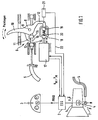
- FIG. 1 shows a transmission 1, which may be for example an automatic transmission or an automated manual transmission.
- the transmission is controlled by an electronic transmission control 2.
- Momentary switching or operating state signals of the transmission 1 are fed via the electronic transmission control 2 a combination element 3 and displayed there to the driver.
- a pivot lever 4 On the gear 1, a pivot lever 4 is provided, which is connected via a cable 5 with a locking device 6. About the pivot lever 4, the cable 5 and the locking device 6 can be prevented or allowed that the transmission 1 switches to a parked state. In the position of the pivot lever shown here, the transmission 1 is not in the park state, but in a different operating state, for example, in idle mode, in the driving mode or in the return mode. In these operating conditions prevails in the transmission 1, a hydraulic pressure, a pivoting of the pivot lever 4 from the in FIG. 1 shown position prevented.
- the electronic transmission control 2 switches the transmission 1 into an operating state in which the hydraulic pressure in the parking lock valve has dropped. In such or other situations in which the hydraulic pressure in the transmission 1 has dropped, switching to the park state is basically possible.
- the park state of the pivot lever 4 is pivoted in the dashed line indicated parking position P, which is designated by the reference numeral 7.
- the locking device 6 is provided.
- a pivot lever 8 is provided, which is arranged pivotably about a pivot axis 9.
- the pivot lever 8 has a lever arm 10 functioning as a "control element”, a pawl 11 and a further lever arm 12.
- a lever arm 10 functioning as a "control element”
- a pawl 11 engages the pawl 11 in a recess 13 of the cable 5 a.
- the recess 13 is formed by two spaced-apart ring members 14, 15, which are interconnected by a central portion 16.
- the cable 5 is pressed by the pressurized hydraulic pressure lever 4 completely to the "right", so that between the pawl 11 and the ring member 15 is a small gap.
- the pawl 11 is thus not or only slightly on the ring member 15 at.
- the pivot lever 8 has a further lever arm 12.
- the further lever arm 12 is mechanically coupled to an electric motor 17 via a drawbar 18 into which a spherical element 19 of the lever arm 12 engages.
- the spherical element 19 is displaceable in the drawbar 18 against the force of a compression spring 20.
- the electric motor 17 is driven by the electronic transmission control 2.
- a position sensor 21 shown here only schematically is provided, which is likewise connected to the electrical transmission control 2 via an electrical line 22.
- the trigger signal for switching to the park state may be, for example, an "engine off signal” in combination with another signal, such as a speed signal, or an "ignition off signal” alone or in combination with other signals.
- the driver can also switch to the parking state "manually".
- “manual” means that the transmission 1 is actively switched automatically into the park state by the driver and not as described above depending on the operating state. This can be done for example by operating a conventional gear selector lever, a park button or a parking lever (not shown).
- a "manual" switching of the transmission 1 in the park state by pressing the pivot lever 8 on the lever arm 10 is possible.
- a hydraulic pressure prevails in the transmission 1 when the transmission is in idling mode, in the driving state or in the reversing state.
- the hydraulic pressure causes the pivoting lever 4 counteracted with a force counterclockwise, whereby the cable 5 is "shifted to the right", so that the pawl 11 is not or only very slightly rests against the ring element 15.
- the driver can thus pivot with a relatively small force, which is determined primarily by the pressure force of the spring 20, the pivot lever 8 in a clockwise direction.
- the drawbar 18 is initially not moved.
- the pivoting movement of the pivoting lever 8 is sensed by the position sensor 21.
- the position sensor 21 supplies a corresponding panning signal to the electronic transmission control 2.
- the electronic transmission control 2 in turn controls the electric motor 17. Instead of an electric motor and an electromagnet can be provided. This pulls the pivot lever 8 on the drawbar 18 to the left, so that the pawl 11, the cable 5 releases. Simultaneously with the signal supplied from the position sensor 21 to the electronic transmission control 2, the electronic transmission control 2 shuts off the hydraulic pressure in the transmission 1 so that the transmission 1 can shift to the park state.
- the electronic transmission control controls the electric motor 17 accordingly, the drawbar shifted to the right and the pivot lever 8 is pivoted back to its original position ,
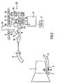
- FIG. 2 shows an embodiment which, in terms of its function, the embodiment of the FIG. 1 is very similar, but which has an additional actuator 23, which can be referred to as “emergency release” for the transmission 1 or as “emergency lock” for the locking device 6.
- the vehicle can safely, that is turned off against rolling away. If the vehicle is subsequently to be towed, however, the parking state must again be "deactivated", ie the cable 5 must be pulled to the "right".
- the cable While in normal operation when building a hydraulic pressure in the transmission 1, the cable is automatically shifted to the right by the hydraulic pressure, in a fault, the pivot lever must be "manually” pulled to the right to disable the park state.
- the cable is connected via a cable pull section, for example via an elastic band 24 with a winding device 25 which can be wound in an emergency, for example via an Allen 26, a hand wheel or the like.
- the pawl 11 engages in the recess 13th and holds the transmission 1 in an unlocked state, for example, in the idle state.
- FIG. 3 shows an embodiment in which the pivot lever 8 is not, as in the embodiments of FIGS. 1 and 2 , is directly operable by a lever arm connected to the pivot lever 8, but by a pushbutton 27.
- a lever arm connected to the pivot lever 8
- a pushbutton 27 a lever arm connected to the pivot lever 8
- FIGS. 1 and 2 explained functions also represented by such a variant with a push button 27.
Landscapes
- Engineering & Computer Science (AREA)
- General Engineering & Computer Science (AREA)
- Mechanical Engineering (AREA)
- Gear-Shifting Mechanisms (AREA)
Claims (16)
- Véhicule équipé d'une boîte de vitesses (1) ainsi que d'une installation de verrouillage (6) coopérant avec la boîte de vitesses (1), et qui à l'état verrouillé, interdit le passage de la boîte de vitesses en mode de stationnement ou qui, à l'état déverrouillé, permet le passage de la boîte de vitesses (1) en mode de stationnement,- un élément de manoeuvre (10, 27) déverrouillant l'installation de verrouillage (6),véhicule caractérisé en ce que
l'élément de manoeuvre (10, 27) fonctionne comme générateur de signal pour un actionneur électromécanique (17) qui déverrouille l'installation de verrouillage (6) de manière électromécanique, et l'élément de manoeuvre (10, 27) fonctionne en outre comme élément de manoeuvre purement mécanique pour déverrouiller l'installation de verrouillage (6) de manière purement mécanique, notamment si l'actionneur électromécanique (17) n'est pas actif. - Véhicule selon la revendication 1,
selon lequel
la boîte de vitesses (1) est reliée à l'installation de verrouillage (6) par une installation de couplage (5), mécanique. - Véhicule selon la revendication 2,
selon lequel
l'installation de couplage (5) est un câble de traction. - Véhicule selon l'une des revendications 2 ou 3,
selon lequel
l'installation de verrouillage (6) est accrochée à l'installation de couplage (5) à l'état verrouillé et interdit à la boîte de vitesses (1) de commuter en mode de stationnement. - Véhicule selon l'une des revendications 2 à 4, comportant un mécanisme à ressort qui, si la boîte de vitesses (1) est à l'état hors pression hydraulique et si l'installation de verrouillage (6) est déverrouillée, déplace l'installation de couplage (5) pour la mettre en mode de stationnement.
- Véhicule selon l'une des revendications 1 à 5,
selon lequel- l'élément de manoeuvre (10, 27) est constitué par le bras de levier d'un levier pivotant (8) accroché à l'installation de couplage (5) à l'état verrouillé, et- l'installation de verrouillage (6) est formée par un élément de verrouillage (11) du levier pivotant (8) et une cavité (13) de l'installation de couplage (5) coopère avec cet élément. - Véhicule selon l'une des revendications 1 à 5,
selon lequel- l'élément de manoeuvre (10, 27) est constitué par un bouton poussoir agissant sur un levier pivotant (8) accroché à l'installation de couplage (5) en position verrouillée, et- l'installation de verrouillage (6) est formée par un élément de verrouillage (11) prévu sur le levier pivotant (8) et une cavité (13) de l'installation de couplage (5) coopère avec cet élément. - Véhicule selon l'une des revendications 1 à 7,
selon lequel
l'élément de manoeuvre (10, 27) se trouve dans l'habitacle du véhicule. - Véhicule selon l'une des revendications 1 à 8,
selon lequel
l'actionneur (17) est couplé au levier pivotant (8) pour que le levier pivotant (8) puisse être pivoté au moins dans le sens du déverrouillage par l'actionneur (17). - Véhicule selon l'une des revendications 1 à 9,
selon lequel
l'actionneur est un moteur électrique (17) ou un électroaimant. - Véhicule selon l'une des revendications 1 à 10,
selon lequel
l'actionneur (17) est couplé au levier pivotant (8) par un élément à ressort (20) de façon que le levier pivotant puisse être pivoté manuellement dans le sens du déverrouillage sans participation de l'actionneur. - Véhicule selon l'une des revendications 1 à 11,
selon lequel
la boîte de vitesses (1) comporte une électronique de commande (2) à laquelle est relié l'élément de manoeuvre (10, 27) fonctionnant comme générateur de signal et l'actionneur (17). - Véhicule selon l'une des revendications 1 à 12,
selon lequel
l'élément de manoeuvre (10, 27) fonctionne comme commutateur de l'actionneur électromécanique. - Véhicule selon l'une des revendications 1 à 13, comportant un capteur de position (21) qui détecte la position de l'installation de verrouillage (6) et qui, lors du déverrouillage de l'installation de verrouillage (6) par l'actionnement de l'élément de manoeuvre (10, 27), génère un signal électrique fourni à l'électronique de commande (2) pour commander l'actionneur (17).
- Véhicule selon l'une des revendications 12 à 14,
selon lequel
l'électronique de commande (2) commute l'installation de verrouillage (6) en commandant l'actionneur (17) vers l'état déverrouillé lorsque le moteur du véhicule est arrêté. - Véhicule selon l'une des revendications 12 à 15,
selon lequel
l'électronique de commande (2) commute l'installation de verrouillage (6) en commandant l'actionneur (17) à l'état déverrouillé lors de la coupure de l'allumage du moteur du véhicule.
Applications Claiming Priority (2)
| Application Number | Priority Date | Filing Date | Title |
|---|---|---|---|
| DE2003144398 DE10344398A1 (de) | 2003-09-25 | 2003-09-25 | Fahrzeug mit einem Getriebe und einem Bedienelement, das zum Entsperren einer Sperreinrichtung vorgesehen ist, um das Getriebe in einen Parkzustand zu schalten |
| DE10344398 | 2003-09-25 |
Publications (3)
| Publication Number | Publication Date |
|---|---|
| EP1519086A2 EP1519086A2 (fr) | 2005-03-30 |
| EP1519086A3 EP1519086A3 (fr) | 2010-09-15 |
| EP1519086B1 true EP1519086B1 (fr) | 2011-10-05 |
Family
ID=34177934
Family Applications (1)
| Application Number | Title | Priority Date | Filing Date |
|---|---|---|---|
| EP20040020595 Expired - Lifetime EP1519086B1 (fr) | 2003-09-25 | 2004-08-31 | Véhicule avec une boîte de vitesse et un elément de commande pour ouvrir un dispositif de fermeture afin de placer la boîte de vitesse à l'état de stationnement |
Country Status (2)
| Country | Link |
|---|---|
| EP (1) | EP1519086B1 (fr) |
| DE (1) | DE10344398A1 (fr) |
Families Citing this family (10)
| Publication number | Priority date | Publication date | Assignee | Title |
|---|---|---|---|---|
| GB2437091A (en) * | 2006-04-10 | 2007-10-17 | Ford Global Tech Llc | Electric park brake system for vehicle with no ignition key |
| DE102006049639B4 (de) * | 2006-10-20 | 2017-04-27 | Audi Ag | Parksperrvorrichtung für Kraftfahrzeuge sowie Verfahren zur Aktivierung und Deaktivierung einer Parksperrvorrichtung |
| JP4833097B2 (ja) | 2007-01-23 | 2011-12-07 | 株式会社デンソー | シフトバイワイヤ装置 |
| JP4412355B2 (ja) * | 2007-06-08 | 2010-02-10 | 株式会社デンソー | シフトレンジ切替装置 |
| DE102009028340A1 (de) | 2009-08-07 | 2011-02-10 | Zf Friedrichshafen Ag | Einrichtung zur Notentriegelung einer Parksperre eines Automatgetriebes eines Kraftfahrzeugs |
| KR101317375B1 (ko) * | 2011-07-21 | 2013-10-10 | 현대자동차주식회사 | 주차 브레이크 시스템 |
| DE102014225603A1 (de) * | 2014-12-11 | 2016-06-16 | Zf Friedrichshafen Ag | Vorrichtung mit einer mechanisch und hydraulisch betätigbaren Parksperre in einem Getriebe |
| EP3067591B1 (fr) * | 2015-03-13 | 2017-10-18 | GETRAG B.V. & Co. KG | Ensemble de verrouillage de stationnement pour boîte de vitesses de véhicule automobile |
| KR102440594B1 (ko) * | 2017-12-11 | 2022-09-05 | 현대자동차 주식회사 | 중립 유지 잠금/해제 장치를 구비하는 변속기 파킹 시스템 |
| CN113028043B (zh) * | 2021-02-03 | 2022-03-22 | 浙江吉利控股集团有限公司 | 一种挡杆式电子换挡器机械出p挡装置 |
Family Cites Families (3)
| Publication number | Priority date | Publication date | Assignee | Title |
|---|---|---|---|---|
| DE19820920B4 (de) * | 1998-05-09 | 2008-07-03 | Bayerische Motoren Werke Aktiengesellschaft | Parksperreneinrichtung für ein automatisches Kraftfahrzeuggetriebe |
| DE10045953B4 (de) * | 2000-09-16 | 2009-07-30 | Volkswagen Ag | Parksperrvorrichtung |
| DE10052260A1 (de) * | 2000-10-19 | 2002-06-13 | Deere & Co | Steuereinrichtung für die Parksperre eines Kraftfahrzeugs |
-
2003
- 2003-09-25 DE DE2003144398 patent/DE10344398A1/de not_active Withdrawn
-
2004
- 2004-08-31 EP EP20040020595 patent/EP1519086B1/fr not_active Expired - Lifetime
Also Published As
| Publication number | Publication date |
|---|---|
| EP1519086A2 (fr) | 2005-03-30 |
| DE10344398A1 (de) | 2005-05-25 |
| EP1519086A3 (fr) | 2010-09-15 |
Similar Documents
| Publication | Publication Date | Title |
|---|---|---|
| EP0246353B1 (fr) | Dispositif de commande pour une boîte de vitesses automatique pour véhicules automobiles | |
| EP2115329B1 (fr) | Dispositif d'actionnement avec actionneur de levier sélecteur | |
| EP0972667B1 (fr) | Véhicule avec transmission automatique à commande électronique et freinage de stationnement commandé par force externe | |
| EP1199234B1 (fr) | Dispositif de déverrouillage de secours pour un frein de stationnement dans un véhicule automobile | |
| DE10212038B4 (de) | Parksperre | |
| EP2927540B1 (fr) | Système de frein de stationnement pour une boîte de vitesses de véhicule et boîte de vitesses en étant équipée | |
| EP1199233B1 (fr) | Dispositif de commande pour un frein de stationnement pour véhicule automobile | |
| EP1190190B1 (fr) | Dispositif de changement de vitesses pour une boite de vehicule automobile | |
| DE10045953B4 (de) | Parksperrvorrichtung | |
| EP2181278A1 (fr) | Procédé de commande de la position neutre d'une boîte automatique ou automatisée d'un véhicule automobile, et véhicule automobile correspondant | |
| DE4125162A1 (de) | Anordnung zur betaetigung einer reibungskupplung eines kraftfahrzeugs, insbesondere eines lastkraftwagens | |
| EP1519086B1 (fr) | Véhicule avec une boîte de vitesse et un elément de commande pour ouvrir un dispositif de fermeture afin de placer la boîte de vitesse à l'état de stationnement | |
| WO2021094347A1 (fr) | Dispositif pour actionner un frein de stationnement dans une boîte de vitesses automatique d'un véhicule automobile | |
| EP1419327B1 (fr) | Unite de commande destinee a la selection de programmes de changements de vitesses ou de rapports d'une boite de vitesses automatique de vehicule | |
| DE19940029B4 (de) | Fahrstufenwähleinrichtung | |
| DE19818864C1 (de) | Wähleinrichtung für ein automatisches Kraftfahrzeuggetriebe | |
| EP1836418B1 (fr) | Dispositif de selection conçu pour une boite de vitesses de vehicule | |
| WO2009010395A1 (fr) | Procédé de commande d'une phase de fonctionnement dans une boîte de vitesse automatique ou automatisée d'un véhicule et véhicule correspondant | |
| DE102007011614A1 (de) | Getriebenotentriegelung | |
| EP1611375A2 (fr) | Changement de vitesses du type shift-by-wire avec position p | |
| DE10131433A1 (de) | Schaltvorrichtung für ein Kraftfahrzeuggetriebe | |
| DE102005046278A1 (de) | Kraftfahrzeug mit einer elektronisch ansteuerbaren Parksperre und mit einer elektronisch ansteuerbaren Feststellbremse | |
| EP0816191B1 (fr) | Dispositif avec sélecteur de vitesse pour boíte de vitesse automatique pour véhicule | |
| DE3744761C2 (de) | Betätigungsvorrichtung für ein automatisches Getriebe in einem Kraftfahrzeug | |
| DE3422056C2 (fr) |
Legal Events
| Date | Code | Title | Description |
|---|---|---|---|
| PUAI | Public reference made under article 153(3) epc to a published international application that has entered the european phase |
Free format text: ORIGINAL CODE: 0009012 |
|
| AK | Designated contracting states |
Kind code of ref document: A2 Designated state(s): AT BE BG CH CY CZ DE DK EE ES FI FR GB GR HU IE IT LI LU MC NL PL PT RO SE SI SK TR |
|
| AX | Request for extension of the european patent |
Extension state: AL HR LT LV MK |
|
| PUAL | Search report despatched |
Free format text: ORIGINAL CODE: 0009013 |
|
| AK | Designated contracting states |
Kind code of ref document: A3 Designated state(s): AT BE BG CH CY CZ DE DK EE ES FI FR GB GR HU IE IT LI LU MC NL PL PT RO SE SI SK TR |
|
| AX | Request for extension of the european patent |
Extension state: AL HR LT LV MK |
|
| 17P | Request for examination filed |
Effective date: 20101005 |
|
| GRAP | Despatch of communication of intention to grant a patent |
Free format text: ORIGINAL CODE: EPIDOSNIGR1 |
|
| RIC1 | Information provided on ipc code assigned before grant |
Ipc: F16H 63/38 20060101AFI20101220BHEP |
|
| GRAS | Grant fee paid |
Free format text: ORIGINAL CODE: EPIDOSNIGR3 |
|
| GRAA | (expected) grant |
Free format text: ORIGINAL CODE: 0009210 |
|
| AK | Designated contracting states |
Kind code of ref document: B1 Designated state(s): DE FR GB IT |
|
| REG | Reference to a national code |
Ref country code: GB Ref legal event code: FG4D Free format text: NOT ENGLISH |
|
| REG | Reference to a national code |
Ref country code: DE Ref legal event code: R096 Ref document number: 502004012923 Country of ref document: DE Effective date: 20111229 |
|
| PLBE | No opposition filed within time limit |
Free format text: ORIGINAL CODE: 0009261 |
|
| STAA | Information on the status of an ep patent application or granted ep patent |
Free format text: STATUS: NO OPPOSITION FILED WITHIN TIME LIMIT |
|
| 26N | No opposition filed |
Effective date: 20120706 |
|
| REG | Reference to a national code |
Ref country code: DE Ref legal event code: R097 Ref document number: 502004012923 Country of ref document: DE Effective date: 20120706 |
|
| REG | Reference to a national code |
Ref country code: FR Ref legal event code: PLFP Year of fee payment: 13 |
|
| REG | Reference to a national code |
Ref country code: FR Ref legal event code: PLFP Year of fee payment: 14 |
|
| REG | Reference to a national code |
Ref country code: FR Ref legal event code: PLFP Year of fee payment: 15 |
|
| P01 | Opt-out of the competence of the unified patent court (upc) registered |
Effective date: 20230503 |
|
| PGFP | Annual fee paid to national office [announced via postgrant information from national office to epo] |
Ref country code: IT Payment date: 20230831 Year of fee payment: 20 Ref country code: GB Payment date: 20230824 Year of fee payment: 20 |
|
| PGFP | Annual fee paid to national office [announced via postgrant information from national office to epo] |
Ref country code: FR Payment date: 20230822 Year of fee payment: 20 Ref country code: DE Payment date: 20230801 Year of fee payment: 20 |
|
| REG | Reference to a national code |
Ref country code: DE Ref legal event code: R071 Ref document number: 502004012923 Country of ref document: DE |
|
| REG | Reference to a national code |
Ref country code: GB Ref legal event code: PE20 Expiry date: 20240830 |
|
| PG25 | Lapsed in a contracting state [announced via postgrant information from national office to epo] |
Ref country code: GB Free format text: LAPSE BECAUSE OF EXPIRATION OF PROTECTION Effective date: 20240830 |
|
| PG25 | Lapsed in a contracting state [announced via postgrant information from national office to epo] |
Ref country code: GB Free format text: LAPSE BECAUSE OF EXPIRATION OF PROTECTION Effective date: 20240830 |