EP1519086B1 - Vehicle with a gearbox and an operating element for unlocking a locking device in order to set the gearbox to parking state - Google Patents
Vehicle with a gearbox and an operating element for unlocking a locking device in order to set the gearbox to parking state Download PDFInfo
- Publication number
- EP1519086B1 EP1519086B1 EP20040020595 EP04020595A EP1519086B1 EP 1519086 B1 EP1519086 B1 EP 1519086B1 EP 20040020595 EP20040020595 EP 20040020595 EP 04020595 A EP04020595 A EP 04020595A EP 1519086 B1 EP1519086 B1 EP 1519086B1
- Authority
- EP
- European Patent Office
- Prior art keywords
- locking device
- vehicle according
- transmission
- state
- actuator
- Prior art date
- Legal status (The legal status is an assumption and is not a legal conclusion. Google has not performed a legal analysis and makes no representation as to the accuracy of the status listed.)
- Expired - Lifetime
Links
- 230000005540 biological transmission Effects 0.000 claims description 68
- 230000008878 coupling Effects 0.000 claims description 18
- 238000010168 coupling process Methods 0.000 claims description 18
- 238000005859 coupling reaction Methods 0.000 claims description 18
- 230000003213 activating effect Effects 0.000 claims 2
- 230000000903 blocking effect Effects 0.000 description 3
- 238000011161 development Methods 0.000 description 3
- 230000018109 developmental process Effects 0.000 description 3
- 230000006835 compression Effects 0.000 description 1
- 238000007906 compression Methods 0.000 description 1
- 230000001419 dependent effect Effects 0.000 description 1
- 238000004091 panning Methods 0.000 description 1
- 238000005096 rolling process Methods 0.000 description 1
- 230000008054 signal transmission Effects 0.000 description 1
- 238000004804 winding Methods 0.000 description 1
Images

Classifications
-
- F—MECHANICAL ENGINEERING; LIGHTING; HEATING; WEAPONS; BLASTING
- F16—ENGINEERING ELEMENTS AND UNITS; GENERAL MEASURES FOR PRODUCING AND MAINTAINING EFFECTIVE FUNCTIONING OF MACHINES OR INSTALLATIONS; THERMAL INSULATION IN GENERAL
- F16H—GEARING
- F16H63/00—Control outputs from the control unit to change-speed- or reversing-gearings for conveying rotary motion or to other devices than the final output mechanism
- F16H63/02—Final output mechanisms therefor; Actuating means for the final output mechanisms
- F16H63/30—Constructional features of the final output mechanisms
- F16H63/34—Locking or disabling mechanisms
- F16H63/3416—Parking lock mechanisms or brakes in the transmission
- F16H63/3491—Emergency release or engagement of parking locks or brakes
-
- F—MECHANICAL ENGINEERING; LIGHTING; HEATING; WEAPONS; BLASTING
- F16—ENGINEERING ELEMENTS AND UNITS; GENERAL MEASURES FOR PRODUCING AND MAINTAINING EFFECTIVE FUNCTIONING OF MACHINES OR INSTALLATIONS; THERMAL INSULATION IN GENERAL
- F16H—GEARING
- F16H61/00—Control functions within control units of change-speed- or reversing-gearings for conveying rotary motion ; Control of exclusively fluid gearing, friction gearing, gearings with endless flexible members or other particular types of gearing
- F16H61/22—Locking of the control input devices
-
- F—MECHANICAL ENGINEERING; LIGHTING; HEATING; WEAPONS; BLASTING
- F16—ENGINEERING ELEMENTS AND UNITS; GENERAL MEASURES FOR PRODUCING AND MAINTAINING EFFECTIVE FUNCTIONING OF MACHINES OR INSTALLATIONS; THERMAL INSULATION IN GENERAL
- F16H—GEARING
- F16H63/00—Control outputs from the control unit to change-speed- or reversing-gearings for conveying rotary motion or to other devices than the final output mechanism
- F16H63/02—Final output mechanisms therefor; Actuating means for the final output mechanisms
- F16H63/30—Constructional features of the final output mechanisms
- F16H63/34—Locking or disabling mechanisms
- F16H63/3416—Parking lock mechanisms or brakes in the transmission
- F16H63/3458—Parking lock mechanisms or brakes in the transmission with electric actuating means, e.g. shift by wire
- F16H63/3475—Parking lock mechanisms or brakes in the transmission with electric actuating means, e.g. shift by wire using solenoids
Definitions
- the present invention relates to a vehicle with a transmission and a control according to the preamble of claim 1, and as it is known from the document DE 198 20 920 A1 is known.
- the object of the invention is to provide a vehicle with a transmission in which both in normal operation and in an emergency operation, the parking brake can be inserted in a simple and secure manner.
- the basic idea of the invention is now to provide a single operating element with which the locking device can be unlocked both in normal operation and in emergency operation.
- the unlocking is done electromechanically via an electrical control, which can be attributed to the "transmission control”.
- the control element acts in normal operation as a "signal generator” for the electrical control or a cooperating electromechanical unlocking or an electromechanical actuator.
- a mechanical "unblocking force" is transmitted to the locking device via the operating element. It is then not electrically or electromechanically, but purely mechanically unlocked, which is required, for example, when the electrical control has failed or out is inactive for a reason. Even with a failure of the electrical control so the parking condition can be engaged and the vehicle safely parked.
- a significant advantage for the driver is that he can "insert" the parking brake on one and the same control in normal operation and emergency operation.
- the transmission is connected via a coupling device, for example via a cable with the locking device.
- the locking device can be locked in the blocking state with the coupling device or locked or otherwise coupled, such that an automatic or unintentional switching of the transmission is prevented in the park state by the coupling device.
- a spring mechanism which, when the transmission is in a certain "hydraulic" state, for example in the above-mentioned hydraulic pressure-free state and the locking device is unlocked, pulls the coupling device or the cable in a park state position.
- the operating element may be formed by an arm of a pivoting lever.
- the pivot lever In the locked state, the pivot lever is locked to the coupling device, wherein a provided on the pivot lever locking element, for example a pawl, is engaged in a cooperating recess of the coupling device.
- the locking device is formed in this case by the blocking element or by the pawl and the recess provided on the coupling device.
- control element may also be formed by a pushbutton, which acts, for example, on a pivoting lever.
- the pivot lever In the locked state, the pivot lever is locked to the coupling device.
- the Locking device by a provided on the pivot lever locking element, for example, a pawl, and a cooperating recess of the coupling device may be formed.
- the operating element is arranged in the passenger compartment of the vehicle, for example in the region of the center console, on the steering wheel or in the region of the steering wheel, on the driver's door or in other areas that are ergonomically accessible to the driver.
- the operating element acts as a signal transmitter for an electromechanical actuator, which is provided for the electromechanical unlocking of the blocking device, at least in some operating states.
- the actuator is preferably connected to the pivot lever, that the pivot lever is pivotable by the actuator in the locking and / or unlocking.
- the actuator may be an electric motor, for example a linear motor or a rotary motor.
- the actuator can be coupled via a spring element and a drawbar with the pivot lever.
- a spring element Upon actuation of the pivot lever by hand in an unlocking the pivot lever can be pivoted without the actuator is moved. Thus, only the spring element is compressed or pulled apart.
- the drawbar is designed so that the pivot lever can be pulled by the actuator in the unlocking direction.
- other mechanical couplings between the actuator and the pivot lever are conceivable.
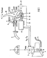
- FIG. 1 shows a transmission 1, which may be for example an automatic transmission or an automated manual transmission.
- the transmission is controlled by an electronic transmission control 2.
- Momentary switching or operating state signals of the transmission 1 are fed via the electronic transmission control 2 a combination element 3 and displayed there to the driver.
- a pivot lever 4 On the gear 1, a pivot lever 4 is provided, which is connected via a cable 5 with a locking device 6. About the pivot lever 4, the cable 5 and the locking device 6 can be prevented or allowed that the transmission 1 switches to a parked state. In the position of the pivot lever shown here, the transmission 1 is not in the park state, but in a different operating state, for example, in idle mode, in the driving mode or in the return mode. In these operating conditions prevails in the transmission 1, a hydraulic pressure, a pivoting of the pivot lever 4 from the in FIG. 1 shown position prevented.
- the electronic transmission control 2 switches the transmission 1 into an operating state in which the hydraulic pressure in the parking lock valve has dropped. In such or other situations in which the hydraulic pressure in the transmission 1 has dropped, switching to the park state is basically possible.
- the park state of the pivot lever 4 is pivoted in the dashed line indicated parking position P, which is designated by the reference numeral 7.
- the locking device 6 is provided.
- a pivot lever 8 is provided, which is arranged pivotably about a pivot axis 9.
- the pivot lever 8 has a lever arm 10 functioning as a "control element”, a pawl 11 and a further lever arm 12.
- a lever arm 10 functioning as a "control element”
- a pawl 11 engages the pawl 11 in a recess 13 of the cable 5 a.
- the recess 13 is formed by two spaced-apart ring members 14, 15, which are interconnected by a central portion 16.
- the cable 5 is pressed by the pressurized hydraulic pressure lever 4 completely to the "right", so that between the pawl 11 and the ring member 15 is a small gap.
- the pawl 11 is thus not or only slightly on the ring member 15 at.
- the pivot lever 8 has a further lever arm 12.
- the further lever arm 12 is mechanically coupled to an electric motor 17 via a drawbar 18 into which a spherical element 19 of the lever arm 12 engages.
- the spherical element 19 is displaceable in the drawbar 18 against the force of a compression spring 20.
- the electric motor 17 is driven by the electronic transmission control 2.
- a position sensor 21 shown here only schematically is provided, which is likewise connected to the electrical transmission control 2 via an electrical line 22.
- the trigger signal for switching to the park state may be, for example, an "engine off signal” in combination with another signal, such as a speed signal, or an "ignition off signal” alone or in combination with other signals.
- the driver can also switch to the parking state "manually".
- “manual” means that the transmission 1 is actively switched automatically into the park state by the driver and not as described above depending on the operating state. This can be done for example by operating a conventional gear selector lever, a park button or a parking lever (not shown).
- a "manual" switching of the transmission 1 in the park state by pressing the pivot lever 8 on the lever arm 10 is possible.
- a hydraulic pressure prevails in the transmission 1 when the transmission is in idling mode, in the driving state or in the reversing state.
- the hydraulic pressure causes the pivoting lever 4 counteracted with a force counterclockwise, whereby the cable 5 is "shifted to the right", so that the pawl 11 is not or only very slightly rests against the ring element 15.
- the driver can thus pivot with a relatively small force, which is determined primarily by the pressure force of the spring 20, the pivot lever 8 in a clockwise direction.
- the drawbar 18 is initially not moved.
- the pivoting movement of the pivoting lever 8 is sensed by the position sensor 21.
- the position sensor 21 supplies a corresponding panning signal to the electronic transmission control 2.
- the electronic transmission control 2 in turn controls the electric motor 17. Instead of an electric motor and an electromagnet can be provided. This pulls the pivot lever 8 on the drawbar 18 to the left, so that the pawl 11, the cable 5 releases. Simultaneously with the signal supplied from the position sensor 21 to the electronic transmission control 2, the electronic transmission control 2 shuts off the hydraulic pressure in the transmission 1 so that the transmission 1 can shift to the park state.
- the electronic transmission control controls the electric motor 17 accordingly, the drawbar shifted to the right and the pivot lever 8 is pivoted back to its original position ,
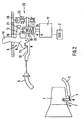
- FIG. 2 shows an embodiment which, in terms of its function, the embodiment of the FIG. 1 is very similar, but which has an additional actuator 23, which can be referred to as “emergency release” for the transmission 1 or as “emergency lock” for the locking device 6.
- the vehicle can safely, that is turned off against rolling away. If the vehicle is subsequently to be towed, however, the parking state must again be "deactivated", ie the cable 5 must be pulled to the "right".
- the cable While in normal operation when building a hydraulic pressure in the transmission 1, the cable is automatically shifted to the right by the hydraulic pressure, in a fault, the pivot lever must be "manually” pulled to the right to disable the park state.
- the cable is connected via a cable pull section, for example via an elastic band 24 with a winding device 25 which can be wound in an emergency, for example via an Allen 26, a hand wheel or the like.
- the pawl 11 engages in the recess 13th and holds the transmission 1 in an unlocked state, for example, in the idle state.
- FIG. 3 shows an embodiment in which the pivot lever 8 is not, as in the embodiments of FIGS. 1 and 2 , is directly operable by a lever arm connected to the pivot lever 8, but by a pushbutton 27.
- a lever arm connected to the pivot lever 8
- a pushbutton 27 a lever arm connected to the pivot lever 8
- FIGS. 1 and 2 explained functions also represented by such a variant with a push button 27.
Landscapes
- Engineering & Computer Science (AREA)
- General Engineering & Computer Science (AREA)
- Mechanical Engineering (AREA)
- Gear-Shifting Mechanisms (AREA)
Description
Die vorliegende Erfindung betrifft ein Fahrzeug mit einem Getriebe und einem Bedienelement gemäß dem Oberbegriff des Patentanspruches 1, und wie es aus dem Dokument
Aus der
Aufgabe der Erfindung ist es, ein Fahrzeug mit einem Getriebe zu schaffen, bei dem sowohl im Normalbetrieb als auch in einem Notbetrieb die Parksperre in einfacher und sicherer Weise eingelegt werden kann.The object of the invention is to provide a vehicle with a transmission in which both in normal operation and in an emergency operation, the parking brake can be inserted in a simple and secure manner.
Diese Aufgabe wird durch die Merkmale des Patentanspruches 1 gelöst. Vorteilhafte Ausgestaltungen und Weiterbildungen der Erfindung sind den Unteransprüchen zu entnehmen.This object is solved by the features of claim 1. Advantageous embodiments and further developments of the invention can be found in the dependent claims.
Die Erfindung geht von einem Fahrzeug mit einem Getriebe aus, das sich in einem Zustand befinden kann, in dem es unter Hydraulikdruck steht oder in einem hydraulikdrucklosen Zustand. Wenn das Getriebe unter Hydraulikdruck steht, wird ein Einlegen der Parksperre durch den Hydraulikdruck verhindert, was im normalen Fahrbetrieb, im Rückfahrbetrieb und im Leerlauf der Fall ist. Wenn es sich im hydraulikdrucklosen Zustand befindet, kann es in einen Parkzustand geschaltet werden. Um zu verhindern, dass das Getriebe selbsttätig in den Parkzustand "fällt", sobald der Hydraulikdruck abfällt, ist eine "Sperreinrichtung" vorgesehen. Die Sperreinrichtung kann sich in einem "Sperrzustand" oder in einem "entsperrten Zustand" befinden. Im Sperrzustand verhindert die Sperreinrichtung, dass das Getriebe in den Parkzustand schaltet bzw. in den Parkzustand fällt. Im entsperrten Zustand gestattet die Sperreinrichtung ein Schalten in den Parkzustand. Ferner ist ein Bedienelement zum Entsperren der Sperreinrichtung vorgesehen.The invention is based on a vehicle with a transmission, which may be in a state in which it is under hydraulic pressure or in a hydraulic pressure-free state. When the transmission is under hydraulic pressure, engagement of the parking brake is prevented by the hydraulic pressure, which is the case in normal driving, in return and idle. If it is in the hydraulic pressure-free state, it can be switched to a park state. In order to prevent the transmission automatically "falling" into the park state as soon as the hydraulic pressure drops, a "locking device" is provided. The locking device may be in a "locked state" or in an "unlocked state". In the locked state prevents the locking device that the transmission switches to the park state or falls into the park state. In the unlocked state, the locking device allows switching to the park state. Furthermore, an operating element for unlocking the locking device is provided.
Der Grundgedanke der Erfindung besteht nun darin, ein einziges Bedienelement vorzusehen, mit dem sowohl im Normalbetrieb als auch in einem Notbetrieb die Sperreinrichtung entsperrt werden kann. Im Normalbetrieb erfolgt die Entsperrung elektromechanisch über eine elektrische Steuerung, die der "Getriebesteuerung" zugerechnet werden kann. Das Bedienelement fungiert im Normalbetrieb als "Signalgeber" für die elektrische Steuerung bzw. eine damit zusammenwirkende elektromechanische Entsperreinrichtung bzw. einen elektromechanischen Aktor. Im Notbetrieb hingegen wird über das Bedienelement eine mechanische "Entsperrkraft" auf die Sperreinrichtung übertragen. Es wird dann also nicht elektrisch bzw. elektromechanisch, sondern rein mechanisch entsperrt, was beispielsweise dann erforderlich ist, wenn die elektrische Steuerung ausgefallen ist oder aus einem bestimmten Grund inaktiv ist. Selbst bei einem Ausfall der elektrischen Steuerung kann also der Parkzustand eingelegt und das Fahrzeug sicher abgestellt werden. Ein wesentlicher Vorteil für den Fahrer besteht darin, dass er im Normalbetrieb und im Notbetrieb die Parksperre über ein und dasselbe Bedienelement "einlegen" kann.The basic idea of the invention is now to provide a single operating element with which the locking device can be unlocked both in normal operation and in emergency operation. In normal operation, the unlocking is done electromechanically via an electrical control, which can be attributed to the "transmission control". The control element acts in normal operation as a "signal generator" for the electrical control or a cooperating electromechanical unlocking or an electromechanical actuator. In emergency mode, however, a mechanical "unblocking force" is transmitted to the locking device via the operating element. It is then not electrically or electromechanically, but purely mechanically unlocked, which is required, for example, when the electrical control has failed or out is inactive for a reason. Even with a failure of the electrical control so the parking condition can be engaged and the vehicle safely parked. A significant advantage for the driver is that he can "insert" the parking brake on one and the same control in normal operation and emergency operation.
Nach einer Weiterbildung der Erfindung ist das Getriebe über eine Kopplungseinrichtung, zum Beispiel über einen Seilzug mit der Sperreinrichtung verbunden. Die Sperreinrichtung ist im Sperrzustand mit der Kopplungseinrichtung verrastbar bzw. verriegelbar oder in sonstiger Weise koppelbar, derart, dass ein selbsttätiges bzw. unbeabsichtigtes Schalten des Getriebes in den Parkzustand durch die Kopplungseinrichtung verhindert wird.According to a development of the invention, the transmission is connected via a coupling device, for example via a cable with the locking device. The locking device can be locked in the blocking state with the coupling device or locked or otherwise coupled, such that an automatic or unintentional switching of the transmission is prevented in the park state by the coupling device.
Nach einer Weiterbildung der Erfindung ist ein Federmechanismus vorgesehen, der, wenn sich das Getriebe in einem bestimmen "hydraulischen" Zustand, zum Beispiel im oben erwähnten hydraulikdrucklosen Zustand befindet und die Sperreinrichtung entsperrt ist, die Kopplungseinrichtung bzw. den Seilzug in eine Parkzustandsstellung zieht.According to a development of the invention, a spring mechanism is provided, which, when the transmission is in a certain "hydraulic" state, for example in the above-mentioned hydraulic pressure-free state and the locking device is unlocked, pulls the coupling device or the cable in a park state position.
Das Bedienelement kann durch einen Arm eines Schwenkhebels gebildet sein. Im Sperrzustand ist der Schwenkhebel mit der Kopplungseinrichtung verrastet, wobei ein am Schwenkhebel vorgesehenes Sperrelement, zum Beispiel eine Sperrklinke, in eine damit zusammenwirkende Ausnehmung der Kopplungseinrichtung eingerastet ist. Die Sperreinrichtung ist in diesem Fall durch das Sperrelement bzw. durch die Sperrklinke und die an der Kopplungseinrichtung vorgesehene Ausnehmung gebildet.The operating element may be formed by an arm of a pivoting lever. In the locked state, the pivot lever is locked to the coupling device, wherein a provided on the pivot lever locking element, for example a pawl, is engaged in a cooperating recess of the coupling device. The locking device is formed in this case by the blocking element or by the pawl and the recess provided on the coupling device.
Alternativ dazu kann das Bedienelement auch durch eine Drucktaste gebildet sein, die zum Beispiel auf einen Schwenkhebel wirkt. Im Sperrzustand ist der Schwenkhebel mit der Kopplungseinrichtung verrastet. Auch hier kann die Sperreinrichtung durch ein am Schwenkhebel vorgesehenes Sperrelement, zum Beispiel eine Sperrklinke, und eine damit zusammenwirkende Ausnehmung der Kopplungseinrichtung gebildet sein.Alternatively, the control element may also be formed by a pushbutton, which acts, for example, on a pivoting lever. In the locked state, the pivot lever is locked to the coupling device. Again, the Locking device by a provided on the pivot lever locking element, for example, a pawl, and a cooperating recess of the coupling device may be formed.
Vorzugsweise ist das Bedienelement im Fahrgastraum des Fahrzeugs angeordnet, zum Beispiel im Bereich der Mittelkonsole, am Lenkrad oder im Bereich des Lenkrades, an der Fahrertür oder in anderen für den Fahrer ergonomisch erreichbaren Bereichen.Preferably, the operating element is arranged in the passenger compartment of the vehicle, for example in the region of the center console, on the steering wheel or in the region of the steering wheel, on the driver's door or in other areas that are ergonomically accessible to the driver.
Wie bereits erwähnt fungiert das Bedienelement zumindest in manchen Betriebszuständen als Signalgeber für einen elektromechanischen Aktor, der zum elektromechanischen Entsperren der Sperreinrichtung vorgesehen ist. Der Aktor ist vorzugsweise so mit dem Schwenkhebel verbunden, dass der Schwenkhebel durch den Aktor in Sperr- und/oder in Entsperrrichtung verschwenkbar ist. Der Aktor kann ein Elektromotor, zum Beispiel ein Linearmotor oder ein Drehmotor sein.As already mentioned, the operating element acts as a signal transmitter for an electromechanical actuator, which is provided for the electromechanical unlocking of the blocking device, at least in some operating states. The actuator is preferably connected to the pivot lever, that the pivot lever is pivotable by the actuator in the locking and / or unlocking. The actuator may be an electric motor, for example a linear motor or a rotary motor.
Der Aktor kann über ein Federelement und eine Zuggabel mit dem Schwenkhebel gekoppelt sein. Bei einer Betätigung des Schwenkhebels von Hand in einer Entsperrrichtung kann der Schwenkhebel verschwenkt werden, ohne dass der Aktor mitbewegt wird. Es wird also lediglich das Federelement zusammengedrückt bzw. auseinandergezogen. Die Zuggabel ist dazu vorgesehen, dass der Schwenkhebel vom Aktor in Entsperrrichtung gezogen werden kann. Selbstverständlich sind auch andere mechanische Kopplungen zwischen dem Aktor und dem Schwenkhebel denkbar.The actuator can be coupled via a spring element and a drawbar with the pivot lever. Upon actuation of the pivot lever by hand in an unlocking the pivot lever can be pivoted without the actuator is moved. Thus, only the spring element is compressed or pulled apart. The drawbar is designed so that the pivot lever can be pulled by the actuator in the unlocking direction. Of course, other mechanical couplings between the actuator and the pivot lever are conceivable.
Im folgenden wir die Erfindung im Zusammenhang mit der Zeichnung näher erläutert. Es zeigen:
-
Figuren 1-3 verschiedene Ausführungsbeispiele gemäß der Erfindung.
-
Figures 1-3 various embodiments according to the invention.
Am Getriebe 1 ist ein Schwenkhebel 4 vorgesehen, der über einen Seilzug 5 mit einer Sperreinrichtung 6 verbunden ist. Über den Schwenkhebel 4, den Seilzug 5 und die Sperreinrichtung 6 kann verhindert bzw. gestattet werden, dass das Getriebe 1 in einen Parkzustand schaltet. In der hier gezeigten Stellung des Schwenkhebels befindet sich das Getriebe 1 nicht im Parkzustand, sondern in einem anderen Betriebszustand, beispielsweise im Leerlaufbetrieb, im Fahrbetriebszustand oder im Rückfahrbetrieb. In diesen Betriebszuständen herrscht im Getriebe 1 ein Hydraulikdruck, der ein Verschwenken des Schwenkhebels 4 aus der in
Wird über einen Wählhebel (nicht dargestellt) der Parkzustand angewählt oder wird der Motor des Fahrzeugs ausgeschaltet, so schaltet die elektronische Getriebesteuerung 2 das Getriebe 1 in einen Betriebszustand, in dem der Hydraulikdruck im Parksperrventil abgefallen ist. In solchen oder anderen Situationen, in denen der Hydraulikdruck im Getriebe 1 abgefallen ist, ist grundsätzlich ein Schalten in den Parkzustand möglich. Im Parkzustand ist der Schwenkhebel 4 in die gestrichelt angedeuteten Parkstellung P geschwenkt, die mit dem Bezugszeichen 7 bezeichnet ist. Um zu verhindern, dass das Getriebe bei einem Abfall des Hydraulikdrucks "selbsttätig" in den Parkzustand "fällt", ist die Sperreinrichtung 6 vorgesehen. Abgesehen von Fällen, in denen der Fahrer den Motor und/oder die Zündung ausschaltet und vorgesehen sein kann, dass das Getriebe 1 "automatisch" in den Parkzustand schaltet, wird grundsätzlich durch die Sperreinrichtung 6 sichergestellt, dass das Getriebe nur dann in den Parkzustand schaltet, wenn der Fahrer die Sperreinrichtung 6 aktiv betätigt. Nur wenn die Sperreinrichtung 6 entsperrt ist kann der Schwenkhebel 4 in seine Parkstellung 7 schwenken.If the parking state is selected via a selector lever (not shown) or the engine of the vehicle is switched off, then the
Im folgenden wird die Sperreinrichtung 6 näher erläutert. Bei dem hier gezeigten Ausführungsbeispiel ist ein Schwenkhebel 8 vorgesehen, der um eine Schwenkachse 9 schwenkbar angeordnet ist. Der Schwenkhebel 8 weist einen als "Bedienelement" fungierenden Hebelarm 10, eine Sperrklinke 11 und einen weiteren Hebelarm 12 auf. In der in
Wie bereits erwähnt, weist der Schwenkhebel 8 einen weiteren Hebelarm 12 auf. Der weitere Hebelarm 12 ist mechanisch mit einem Elektromotor 17 gekoppelt und zwar über eine Zuggabel 18, in die ein kugelförmiges Element 19 des Hebelarms 12 eingreift. Das kugelförmige Element 19 ist in der Zuggabel 18 entgegen der Kraft einer Druckfeder 20 verschiebbar. Der Elektromotor 17 wird durch die elektronische Getriebesteuerung 2 angesteuert. Ferner ist ein hier nur schematisch dargestellter Positionssensor 21 vorgesehen, der über eine elektrische Leitung 22 ebenfalls mit der elektrischen Getriebesteuerung 2 verbunden ist.As already mentioned, the
Im folgenden wird die Funktionsweise näher erläutert. Wenn sich das Getriebe 1 im Leerlaufbetrieb, im Fahrzustand oder im Rückfahrzustand befindet und der Motor ausgeschaltet wird, fällt der Hydraulikdruck im Getriebe ab, was dazu führt, dass der Schwenkhebel 4 versucht in die gestrichelt dargestellte P-Stellung 7 zu schwenken. Dies ist jedoch nur dann möglich, wenn der Schwenkhebel 8 in Entsperrrichtung verschwenkt wird und die Sperrklinke 11 ausser Eingriff kommt. Das Abschalten des Motors wird von der elektronischen Getriebesteuerung 2 sensiert. Die elektronische Getriebesteuerung 2 steuert daraufhin den Elektromotor 17 an, der die Zuggabel 18 nach "links" zieht und den Schwenkhebel 8 im Uhrzeigersinn verschwenkt. Durch Verschwenken des Schwenkhebels 8 im Uhrzeigersinn gibt die Sperrklinke 11 den Seilzug 5 frei und das Getriebe 1 kann in den Parkzustand schalten. Auslösesignal für das Umschalten in den Parkzustand kann also beispielsweise ein "Motor-Aus-Signal" in Kombination mit einem weiteren Signal, wie zum Beispiel einem Geschwindigkeitssignal, sein, oder ein "Zündung-Aus-Signal" allein oder in Kombination mit weiteren Signalen.The following explains the functionality in more detail. When the transmission 1 is in the idling, in the driving state or in the reversing state and the engine is turned off, the hydraulic pressure in the transmission drops from what causes the pivot lever 4 tries to pivot in the dashed P-
Wenn sich das Getriebe 1 im Leerlaufzustand, im Fahrzustand oder im Rückfahrzustand befindet, kann der Fahrer auch "manuell" in den Parkzustand schalten. "Manuell" bedeutet in diesem Zusammenhang, dass das Getriebe 1 aktiv vom Fahrer und nicht wie oben beschrieben betriebszustandsabhängig automatisch in den Parkzustand geschaltet wird. Dies kann beispielsweise durch Betätigen eines herkömmlichen Getriebewählhebels, einer Park-Taste oder eines Park-Hebels (nicht dargestellt) erfolgen.When the transmission 1 is in the idling state, in the driving state or in the reversing state, the driver can also switch to the parking state "manually". In this context, "manual" means that the transmission 1 is actively switched automatically into the park state by the driver and not as described above depending on the operating state. This can be done for example by operating a conventional gear selector lever, a park button or a parking lever (not shown).
Alternativ oder ergänzend dazu ist ein "manuelles" Umschalten des Getriebes 1 in den Parkzustand durch Betätigen des Schwenkhebels 8 am Hebelarm 10 möglich. Wie bereits erwähnt herrscht im Getriebe 1 ein Hydraulikdruck, wenn sich das Getriebe im Leerlaufbetrieb, im Fahrzustand oder im Rückfahrzustand befindet. Der Hydraulikdruck bewirkt, dass der Schwenkhebel 4 entgegen den Uhrzeigersinn mit einer Kraft beaufschlagt wird, wodurch der Seilzug 5 "nach rechts" verschoben wird, so dass die Sperrklinke 11 nicht oder nur ganz leicht an dem Ringelement 15 anliegt.Alternatively or additionally, a "manual" switching of the transmission 1 in the park state by pressing the
Der Fahrer kann somit mit einer relativ geringen Kraft, die primär durch die Druckkraft der Feder 20 bestimmt ist, den Schwenkhebel 8 im Uhrzeigersinn verschwenken. Die Zuggabel 18 wird dabei zunächst nicht verschoben. Die Schwenkbewegung des Schwenkhebels 8 wird durch den Positionssensor 21 sensiert. Der Positionssensor 21 liefert ein entsprechendes Schwenksignal an die elektronische Getriebesteuerung 2. Die elektronische Getriebesteuerung 2 wiederum steuert den Elektromotor 17 an. Anstatt eines Elektromotors kann auch ein Elektromagnet vorgesehen sein. Dieser zieht den Schwenkhebel 8 über die Zuggabel 18 nach links, so dass die Sperrklinke 11 den Seilzug 5 freigibt. Gleichzeitig mit dem vom Positionssensor 21 an die elektronische Getriebesteuerung 2 gelieferten Signal schaltet die elektronische Getriebesteuerung 2 den Hydraulikdruck im Getriebe 1 ab, so dass das Getriebe 1 in den Parkzustand umschalten kann.The driver can thus pivot with a relatively small force, which is determined primarily by the pressure force of the
Wenn anschließend wieder über ein Wählelement (nicht dargestellt) in den Leerlaufbetrieb, in den Fahrzustand oder in den Rückfahrzustand umgeschaltet werden soll, steuert die elektronische Getriebesteuerung den Elektromotor 17 entsprechend an, wobei die Zuggabel nach rechts verschoben und der Schwenkhebel 8 in seine Ausgangsstellung zurückgeschwenkt wird.If subsequently to be switched over again via a selection element (not shown) in the idle mode, in the driving state or in the reverse state, the electronic transmission control controls the
Wie bereits angedeutet, betreffen die oben beschriebenen Funktionen den "Normalbetrieb", in dem insbesondere die elektronische Getriebesteuerung und der Motor 17 ordnungsgemäß arbeiten. Wenn der Motor und/oder die Zündung des Fahrzeugs ausgeschaltet ist, oder wenn eine Störung der elektronischen Getriebesteuerung vorliegt, fällt dem Getriebe 1 der Hydraulikdruck ab, was dazu führt, dass der Schwenkhebel 4 versucht, in die Parkstellung 7 zu schwenken. Dies wird jedoch grundsätzlich verhindert, da im Sperrzustand das ringartige Element 15 an der Sperrklinke 11 anliegt. Bei einem Ausfall der Elektronik bzw. bei abgeschaltetem Motor oder abgeschalteter Zündung kann der Schwenkhebel 8 jedoch nach wie vor von Hand im Uhrzeigersinn verschwenkt werden. Durch Verschwenken des Schwenkhebels 8 im Uhrzeigersinn kann der Seilzug 5 rein mechanisch entriegelt werden, so dass auch in solchen Fällen das Getriebe 1, wenn vom Fahrer gewünscht, in den Parkzustand schalten kann.As already indicated, the functions described above relate to "normal operation" in which, in particular, the electronic transmission control and the
Wie bereits im Zusammenhang mit
In diesem Zustand kann das Fahrzeug sicher, das heißt gegen Wegrollen gesichert abgestellt werden. Wenn das Fahrzeug anschließend abgeschleppt werden soll, muss jedoch der Parkzustand wieder "deaktiviert" werden, das heißt der Seilzug 5 muss nach "rechts" gezogen werden. Während im Normalbetrieb beim Aufbau eines Hydraulikdrucks im Getriebe 1 der Seilzug automatisch durch den Hydraulikdruck nach rechts verschoben wird, muss bei einer Störung der Schwenkhebel "manuell" nach rechts gezogen werden, um den Parkzustand zu deaktivieren. Hierzu ist der Seilzug über einen Seilzugabschnitt, zum Beispiel über ein elastisches Band 24 mit einer Aufwickelvorrichtung 25 verbunden, die im Notfall zum Beispiel über einen Inbus 26, ein Handrad oder ähnliches aufwickelbar ist. Wenn der Seilzug 5 wieder nach rechts gezogen wurde, rastet die Sperrklinke 11 in die Ausnehmung 13 ein und hält das Getriebe 1 in einem entsperrten Zustand z.B. im Leerlaufzustand.In this state, the vehicle can safely, that is turned off against rolling away. If the vehicle is subsequently to be towed, however, the parking state must again be "deactivated", ie the
Claims (16)
- A vehicle with a transmission (1), a locking device (6), which cooperates with the transmission (1) and which is in a locking state, in which it prevents the transmission being shifted into a parking state, or in an unlocked state, in which it allows a shifting of the transmission (1) into the parking state, an operating element (10, 27), which is provided to unlock the locking device (6), characterised in that the operating element (10, 27) acts as a signal transmitter for an electromechanical actuator (17), which is provided for the electromechanical unlocking of the locking device (6) and the operating element (10 27) additionally acts as a purely mechanical actuating element for the purely mechanical unlocking of the locking device (6), especially when the electromechanical actuator (17) is inactive.
- A vehicle according to claim 1, wherein the transmission (1) is connected by a mechanical coupling device (5) to the locking device (6).
- A vehicle according to claim 2, wherein the coupling device (5) is a cable pull.
- A vehicle according to either of claims 2 or 3, wherein the locking device (6) can be latched to the coupling device (5) in the locking state and prevents the transmission (1) being shifted into the parking state.
- A vehicle according to any one of claims 2 to 4, wherein a spring mechanism is provided which, when the transmission (1) is in a hydraulic pressureless state and the locking device (6) is unlocked, moves the coupling device (5) into a parking state position.
- A vehicle according to any one of claims 1 to 5, wherein the operating element (10, 27) is formed by a lever arm of a pivot lever (8), which, in the locking state, is latched to the coupling device (5), wherein the locking device (6) is formed by a locking element (11) provided on the pivot lever (8) and a recess (13), which cooperates therewith, of the coupling device (5).
- A vehicle according to any one of claims 1 to 5, wherein the operating element (10, 27) is formed by a push button, which acts on a pivot lever (8), which, in the locking state, is latched to the coupling device (5), wherein the locking device (6) is formed by a locking element (11) provided on the pivot lever (8) and a recess (13), which cooperates therewith, of the coupling device (5).
- A vehicle according to any one of claims 1 to 7, wherein the operating element (10, 27) is arranged in a passenger compartment of the vehicle.
- A vehicle according to any one of claims 1 to 8, wherein the actuator (17) is coupled to the pivot lever (8) in
such a way that the pivot lever (8) can be pivoted by the actuator (17) at least in an unlocking direction. - A vehicle according to any one of claims 1 to 9, wherein the actuator is an electric motor (17) or an electromagnet.
- A vehicle according to any one of claims 1 to 10, wherein the actuator (17) is coupled by a spring element (20) to the pivot lever (8) in such a way that the pivot lever can be pivoted by hand in an unlocking direction, without the actuator also being moved.
- A vehicle according to any one of claims 1 to 11, wherein an electronic control system (2) is provided for the transmission (1), to which the operating element (10, 27) acting as a signal transmitter and the actuator (17) are connected.
- A vehicle according to any one of claims 1 to 12, wherein the operating element (10, 27) acts as a switch for the electromechanical actuator.
- A vehicle according to any one of claims 1 to 13, wherein a position sensor (21) is provided, which senses the position of the locking device (6) and which when the locking device (6) is unlocked by actuating the operating element (10, 27), supplies an electric signal to the electronic control system (10) to activate the actuator (17).
- A vehicle according to any one of claims 12 to 14, wherein the electronic control system (2) shifts the locking device (6) into the unlocked state by activating the actuator (17) if a vehicle engine is switched off.
- A vehicle according to any one of claims :12 to 15, wherein the electronic control system (2) shifts the locking device (6) into the unlocked state by activating the actuator (17), if an ignition of the vehicle engine is switched off.
Applications Claiming Priority (2)
| Application Number | Priority Date | Filing Date | Title |
|---|---|---|---|
| DE2003144398 DE10344398A1 (en) | 2003-09-25 | 2003-09-25 | Vehicle having a transmission and a control element, which is provided for unlocking a locking device to switch the transmission in a park state |
| DE10344398 | 2003-09-25 |
Publications (3)
| Publication Number | Publication Date |
|---|---|
| EP1519086A2 EP1519086A2 (en) | 2005-03-30 |
| EP1519086A3 EP1519086A3 (en) | 2010-09-15 |
| EP1519086B1 true EP1519086B1 (en) | 2011-10-05 |
Family
ID=34177934
Family Applications (1)
| Application Number | Title | Priority Date | Filing Date |
|---|---|---|---|
| EP20040020595 Expired - Lifetime EP1519086B1 (en) | 2003-09-25 | 2004-08-31 | Vehicle with a gearbox and an operating element for unlocking a locking device in order to set the gearbox to parking state |
Country Status (2)
| Country | Link |
|---|---|
| EP (1) | EP1519086B1 (en) |
| DE (1) | DE10344398A1 (en) |
Families Citing this family (10)
| Publication number | Priority date | Publication date | Assignee | Title |
|---|---|---|---|---|
| GB2437091A (en) * | 2006-04-10 | 2007-10-17 | Ford Global Tech Llc | Electric park brake system for vehicle with no ignition key |
| DE102006049639B4 (en) * | 2006-10-20 | 2017-04-27 | Audi Ag | Parking lock device for motor vehicles and method for activating and deactivating a parking lock device |
| JP4833097B2 (en) | 2007-01-23 | 2011-12-07 | 株式会社デンソー | Shift-by-wire device |
| JP4412355B2 (en) * | 2007-06-08 | 2010-02-10 | 株式会社デンソー | Shift range switching device |
| DE102009028340A1 (en) | 2009-08-07 | 2011-02-10 | Zf Friedrichshafen Ag | Device for emergency release of a parking brake of an automatic transmission of a motor vehicle |
| KR101317375B1 (en) * | 2011-07-21 | 2013-10-10 | 현대자동차주식회사 | Parking brake system |
| DE102014225603A1 (en) * | 2014-12-11 | 2016-06-16 | Zf Friedrichshafen Ag | Device with a mechanically and hydraulically actuated parking brake in a transmission |
| EP3067591B1 (en) * | 2015-03-13 | 2017-10-18 | GETRAG B.V. & Co. KG | Parking lock assembly for a motor vehicle transmission |
| KR102440594B1 (en) * | 2017-12-11 | 2022-09-05 | 현대자동차 주식회사 | Transmission parking system including neutral state maintaining lock and release device |
| CN113028043B (en) * | 2021-02-03 | 2022-03-22 | 浙江吉利控股集团有限公司 | A lever-type electronic shifter mechanical P-block device |
Family Cites Families (3)
| Publication number | Priority date | Publication date | Assignee | Title |
|---|---|---|---|---|
| DE19820920B4 (en) * | 1998-05-09 | 2008-07-03 | Bayerische Motoren Werke Aktiengesellschaft | Parking lock device for an automatic motor vehicle transmission |
| DE10045953B4 (en) * | 2000-09-16 | 2009-07-30 | Volkswagen Ag | Parking lock device |
| DE10052260A1 (en) * | 2000-10-19 | 2002-06-13 | Deere & Co | Control device for the parking lock of a motor vehicle |
-
2003
- 2003-09-25 DE DE2003144398 patent/DE10344398A1/en not_active Withdrawn
-
2004
- 2004-08-31 EP EP20040020595 patent/EP1519086B1/en not_active Expired - Lifetime
Also Published As
| Publication number | Publication date |
|---|---|
| EP1519086A2 (en) | 2005-03-30 |
| DE10344398A1 (en) | 2005-05-25 |
| EP1519086A3 (en) | 2010-09-15 |
Similar Documents
| Publication | Publication Date | Title |
|---|---|---|
| EP0246353B1 (en) | Actuating device for an automatic gearbox in an automotive vehicle | |
| EP2115329B1 (en) | Actuating device having a selector lever actuator | |
| EP0972667B1 (en) | Vehicle with electronic controlled automatic transmission and power-assisted parking brake | |
| EP1199234B1 (en) | Emergency unlocking device for a parking brake in a motor vehicle | |
| DE10212038B4 (en) | parking lock | |
| EP2927540B1 (en) | Parking lock system for a motor vehicle transmission and motor vehicle transmission using the same | |
| EP1199233B1 (en) | Control device for a park-lock mechanism for motor vehicle | |
| EP1190190B1 (en) | Shifting device for an automobile gearbox | |
| DE10045953B4 (en) | Parking lock device | |
| EP2181278A1 (en) | Method for actuating the neutral position in an automatic or automated transmission of a motor vehicle, and corresponding motor vehicle | |
| DE4125162A1 (en) | ARRANGEMENT FOR ACTUATING A FRICTION COUPLING OF A MOTOR VEHICLE, IN PARTICULAR A TRUCK | |
| EP1519086B1 (en) | Vehicle with a gearbox and an operating element for unlocking a locking device in order to set the gearbox to parking state | |
| WO2021094347A1 (en) | Device for actuating a park lock in an automatic transmission of a motor vehicle | |
| EP1419327B1 (en) | Control unit gear or shift program selection of an automatic vehicle gearbox | |
| DE19940029B4 (en) | Fahrstufenwähleinrichtung | |
| DE19818864C1 (en) | Selector device for automatic or partially automatic gearbox in motor vehicle | |
| EP1836418B1 (en) | Shifting device for a vehicle transmission | |
| WO2009010395A1 (en) | Method for actuating a gear step in an automatic or automated transmission of a motor vehicle and corresponding motor vehicle | |
| DE102007011614A1 (en) | Gearing system for a vehicle comprises an emergency actuating unit coupled with a gear selector so that the parking gear is deactivated when the gear selector is actuated | |
| EP1611375A2 (en) | Shift-by-wire gearshift mechanism comprising a p-position | |
| DE10131433A1 (en) | Shift arrangement for motor vehicle gearbox has steering column shift lever movable along one direction into stable forward drive, neutral and reversing settings detected to operate gearbox | |
| DE102005046278A1 (en) | Vehicle comprises a device with a control unit and a central operating element assigned to the parking brake and to the locking brake | |
| EP0816191B1 (en) | Device with gear selector lever for an automobile automatic gearbox | |
| DE3744761C2 (en) | Actuator for an automatic transmission in a motor vehicle | |
| DE3422056C2 (en) |
Legal Events
| Date | Code | Title | Description |
|---|---|---|---|
| PUAI | Public reference made under article 153(3) epc to a published international application that has entered the european phase |
Free format text: ORIGINAL CODE: 0009012 |
|
| AK | Designated contracting states |
Kind code of ref document: A2 Designated state(s): AT BE BG CH CY CZ DE DK EE ES FI FR GB GR HU IE IT LI LU MC NL PL PT RO SE SI SK TR |
|
| AX | Request for extension of the european patent |
Extension state: AL HR LT LV MK |
|
| PUAL | Search report despatched |
Free format text: ORIGINAL CODE: 0009013 |
|
| AK | Designated contracting states |
Kind code of ref document: A3 Designated state(s): AT BE BG CH CY CZ DE DK EE ES FI FR GB GR HU IE IT LI LU MC NL PL PT RO SE SI SK TR |
|
| AX | Request for extension of the european patent |
Extension state: AL HR LT LV MK |
|
| 17P | Request for examination filed |
Effective date: 20101005 |
|
| GRAP | Despatch of communication of intention to grant a patent |
Free format text: ORIGINAL CODE: EPIDOSNIGR1 |
|
| RIC1 | Information provided on ipc code assigned before grant |
Ipc: F16H 63/38 20060101AFI20101220BHEP |
|
| GRAS | Grant fee paid |
Free format text: ORIGINAL CODE: EPIDOSNIGR3 |
|
| GRAA | (expected) grant |
Free format text: ORIGINAL CODE: 0009210 |
|
| AK | Designated contracting states |
Kind code of ref document: B1 Designated state(s): DE FR GB IT |
|
| REG | Reference to a national code |
Ref country code: GB Ref legal event code: FG4D Free format text: NOT ENGLISH |
|
| REG | Reference to a national code |
Ref country code: DE Ref legal event code: R096 Ref document number: 502004012923 Country of ref document: DE Effective date: 20111229 |
|
| PLBE | No opposition filed within time limit |
Free format text: ORIGINAL CODE: 0009261 |
|
| STAA | Information on the status of an ep patent application or granted ep patent |
Free format text: STATUS: NO OPPOSITION FILED WITHIN TIME LIMIT |
|
| 26N | No opposition filed |
Effective date: 20120706 |
|
| REG | Reference to a national code |
Ref country code: DE Ref legal event code: R097 Ref document number: 502004012923 Country of ref document: DE Effective date: 20120706 |
|
| REG | Reference to a national code |
Ref country code: FR Ref legal event code: PLFP Year of fee payment: 13 |
|
| REG | Reference to a national code |
Ref country code: FR Ref legal event code: PLFP Year of fee payment: 14 |
|
| REG | Reference to a national code |
Ref country code: FR Ref legal event code: PLFP Year of fee payment: 15 |
|
| P01 | Opt-out of the competence of the unified patent court (upc) registered |
Effective date: 20230503 |
|
| PGFP | Annual fee paid to national office [announced via postgrant information from national office to epo] |
Ref country code: IT Payment date: 20230831 Year of fee payment: 20 Ref country code: GB Payment date: 20230824 Year of fee payment: 20 |
|
| PGFP | Annual fee paid to national office [announced via postgrant information from national office to epo] |
Ref country code: FR Payment date: 20230822 Year of fee payment: 20 Ref country code: DE Payment date: 20230801 Year of fee payment: 20 |
|
| REG | Reference to a national code |
Ref country code: DE Ref legal event code: R071 Ref document number: 502004012923 Country of ref document: DE |
|
| REG | Reference to a national code |
Ref country code: GB Ref legal event code: PE20 Expiry date: 20240830 |
|
| PG25 | Lapsed in a contracting state [announced via postgrant information from national office to epo] |
Ref country code: GB Free format text: LAPSE BECAUSE OF EXPIRATION OF PROTECTION Effective date: 20240830 |
|
| PG25 | Lapsed in a contracting state [announced via postgrant information from national office to epo] |
Ref country code: GB Free format text: LAPSE BECAUSE OF EXPIRATION OF PROTECTION Effective date: 20240830 |