EP1519052A2 - Lüfter eines Kühlgebläses - Google Patents
Lüfter eines Kühlgebläses Download PDFInfo
- Publication number
- EP1519052A2 EP1519052A2 EP04021424A EP04021424A EP1519052A2 EP 1519052 A2 EP1519052 A2 EP 1519052A2 EP 04021424 A EP04021424 A EP 04021424A EP 04021424 A EP04021424 A EP 04021424A EP 1519052 A2 EP1519052 A2 EP 1519052A2
- Authority
- EP
- European Patent Office
- Prior art keywords
- fan
- hub
- fan according
- air passage
- passage openings
- Prior art date
- Legal status (The legal status is an assumption and is not a legal conclusion. Google has not performed a legal analysis and makes no representation as to the accuracy of the status listed.)
- Granted
Links
- 238000001816 cooling Methods 0.000 title claims abstract description 16
- 230000001419 dependent effect Effects 0.000 claims description 3
- 238000009825 accumulation Methods 0.000 claims 1
- 238000009423 ventilation Methods 0.000 abstract 1
- 239000003570 air Substances 0.000 description 31
- 239000002826 coolant Substances 0.000 description 4
- 238000011144 upstream manufacturing Methods 0.000 description 3
- 239000012080 ambient air Substances 0.000 description 1
- 230000000694 effects Effects 0.000 description 1
- 238000005265 energy consumption Methods 0.000 description 1
- 239000012530 fluid Substances 0.000 description 1
Images

Classifications
-
- F—MECHANICAL ENGINEERING; LIGHTING; HEATING; WEAPONS; BLASTING
- F04—POSITIVE - DISPLACEMENT MACHINES FOR LIQUIDS; PUMPS FOR LIQUIDS OR ELASTIC FLUIDS
- F04D—NON-POSITIVE-DISPLACEMENT PUMPS
- F04D29/00—Details, component parts, or accessories
- F04D29/26—Rotors specially for elastic fluids
- F04D29/32—Rotors specially for elastic fluids for axial flow pumps
- F04D29/325—Rotors specially for elastic fluids for axial flow pumps for axial flow fans
- F04D29/329—Details of the hub
-
- F—MECHANICAL ENGINEERING; LIGHTING; HEATING; WEAPONS; BLASTING
- F04—POSITIVE - DISPLACEMENT MACHINES FOR LIQUIDS; PUMPS FOR LIQUIDS OR ELASTIC FLUIDS
- F04D—NON-POSITIVE-DISPLACEMENT PUMPS
- F04D29/00—Details, component parts, or accessories
- F04D29/58—Cooling; Heating; Diminishing heat transfer
- F04D29/582—Cooling; Heating; Diminishing heat transfer specially adapted for elastic fluid pumps
Definitions
- the invention relates to a fan of a cooling fan for at least one back pressure applied heat exchanger of a motor vehicle after the Preamble of claim 1.
- Fans of cooling fans are usually designed as axial fans, in which Axial blades circumferentially arranged on a driven fan hub are.
- the fan is behind a heat exchanger, z. B. a coolant radiator, a charge air cooler or condenser or something called Cooling module arranged and sucks ambient air through the or the heat exchanger.
- a fan guard is arranged with a frame in which the Fan rotates.
- the axial fans Also designed as a so-called shell fan, as by DE 33 04 297 C2 known to the applicant.
- the fan runs in a frame a fan cover to. Also advantageous is an arrangement of the fan in the air flow direction behind the heat exchanger.
- the air passage openings arranged in the hub face and there preferably in Form of circular sectors formed.
- the closure elements are corresponding
- the openings also formed a circular sector, so they completely free, completely free or partially free.
- the fan hub thus consists of two mutually rotatable parts, between which advantageously springs and drivers are arranged.
- the closure elements arranged as a circular segment-shaped flaps, in the air flow direction swing out to the rear and thus a passage cross-section release for the ram air.
- the hinged flaps become stationary Fans are opened by a spring and close automatically with driven fan due to centrifugal effect on the pivoting flaps, which extends from an axial position to a radial position move.
- This arrangement also has the advantage of an automatic Adjustment of the flaps.
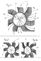
- Fig. 1 shows - in a view from the rear - an axial fan 1 partially with a hub 2, on whose circumference sickle-shaped fan blades 3 are arranged.
- the hub 2 has a hub end face 4, in which three circular sector-shaped cut-outs 5 are arranged as air passage openings.
- a drive shaft 6 is arranged, via which the fan 1 by a drive, not shown here, for. B. is driven by a belt drive.
- an aperture disk 8 with three circular sector-shaped aperture sections 7 is rotatably arranged.
- the illustration shows the fan hub 2 with half-opened or half-closed air passage openings 5; one half is thus covered in each case by the section 7 of the diaphragm disc 8.
- the fan 1, a so-called sickle fan is - as above the state of Engineering carried out - behind a heat exchanger, not shown, in particular behind a coolant radiator arranged in the front Engine compartment of a motor vehicle is arranged.
- the fan 1 sucks in cooling air through the upstream of him arranged, not shown heat exchanger and thus generates a cooling air flow.
- the fan 1 is - like known - temperature-controlled, d. H. he switches depending on the temperature the medium to be cooled on or off. At high speed of the motor vehicle the fan 1 is usually switched off, d. H. the one in front of him Cooling module or the coolant cooler are then acted upon by ram air and flows through.
- the air passage openings 5 is opened in the hub end face 4, so that the ram air can flow through the openings 5. From the back of the hub face 4 gets the air into the engine compartment and from there into the open air.
- the release of the air passage openings 5 takes place by rotating the diaphragm disc 8 clockwise, d. H. opposite to the direction of the arrow P, and automatically, as described below:
- the drive shaft 6 is in a manner not shown with the aperture disc 8, and between the diaphragm disc 8 and the hub face 4 and the hub 2 is a spring, not shown, for. B. a torsion spring interposed.
- This torsion spring causes the drive torque transmitted from the drive shaft 6 via the torsion spring on the fan hub 2 becomes.
- 7 drivers 9 are arranged on the edge of the diaphragm sections. This means that when driving the diaphragm disc 8 in the direction of the arrow P first, the openings 5 are closed until the driver 9 hit the hub face 4 and take this. Consequently there is an automatic closure of the air passage openings 5 with driven Fan 1.
- Fig. 2 shows the fan of FIG. 1 (same reference numerals are used) in a view from the rear, with fully closed hub face 4, ie the openings 5 are fully covered by the sections 7.
- FIG. 2 a shows the fan according to FIG. 2 in a view from the front with the completely visible diaphragm disc 8, which is rotatably arranged in front of the hub end face 4 in the air flow direction.
- FIG. 3 shows the fan according to FIG. 1 in a view from the rear, with half-opened hub end face 4, ie FIG. 3 corresponds to FIG. 1.
- Fig. 3a shows the fan of FIG. 3 in a front view with complete aperture disc 8, which consists of the three diaphragm sections 7 and a central hub portion 8a.
- Fig. 4 shows the fan of FIG. 1 in a view from the rear, with fully open hub, ie the air passage openings 5 are completely released.
- Fig. 4a shows the fan of FIG. 4 in a view from the front with the released air passage openings 5, which are thus fully flowed through by the ram air flow.
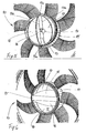
- Fig. 5 shows a second embodiment of the invention, namely a fan 10 with a cylindrical hub 11, which has a hub face 12.
- a fan 10 with a cylindrical hub 11, which has a hub face 12.
- the web 13 furthermore has longitudinal sides 13b, on which two flaps 15, 16 are arranged, each of which has a circular or arcuate axis (for example a film hinge).
- the flaps 15, 16 are folded backwards in the direction of travel, ie they release part of the hub end face 12. This position take the flaps 15, 16 with the fan stopped, so for example when driving fast of the motor vehicle.
- the flaps 15, 16 are preferably held together by a tension spring, not shown, acting on both flaps.
- FIG. 6 shows the fan 10 according to FIG. 5 in a front view, ie opposite to the direction of travel and in the direction of air flow.
- the hub end face 12 thus has two circular segment-shaped, almost semicircular air passage openings 17, 18, through which the ram air can flow.
- attack on the flaps 15, 16 centrifugal forces, which move the flaps 15, 16 in a radially oriented position, ie in a radial plane, and thus in the closed position.
- the above-mentioned tension spring opens the flaps 15, 16 again.
Landscapes
- Engineering & Computer Science (AREA)
- Mechanical Engineering (AREA)
- General Engineering & Computer Science (AREA)
- Physics & Mathematics (AREA)
- Thermal Sciences (AREA)
- Structures Of Non-Positive Displacement Pumps (AREA)
- Cooling, Air Intake And Gas Exhaust, And Fuel Tank Arrangements In Propulsion Units (AREA)
Abstract
Description
- Fig. 1
- eine Lüfternabe mit kreissektorförmigen Durchlassöffnungen,
- Fig. 2
- die Lüfternabe in einer Ansicht von hinten mit geschlossenen Öffnungen,
- Fig. 2a
- die Lüfternabe gemäß Fig. 2 in einer Ansicht von vorn,
- Fig. 3
- die Lüfternabe mit halb geschlossenen Öffnungen in einer Ansicht von hinten,
- Fig. 3a
- die Lüfternabe gemäß Fig. 3 in einer Ansicht von vorn,
- Fig. 4
- die Lüfternabe mit freigegebenen Öffnungen in einer Ansicht von hinten,
- Fig. 4a
- die Lüfternabe gemäß Fig. 4 in einer Ansicht von vorn,
- Fig. 5
- eine Lüfternabe mit kreissegmentförmigen Durchtrittsöffnungen in einer Ansicht von hinten und
- Fig. 6
- die Lüfternabe gemäß Fig. 5 in einer Ansicht von vorn.
Claims (11)
- Lüfter eines Kühlgebläses für mindestens einen stauluftbeaufschlagbaren Wärmeübertrager eines Kraftfahrzeuges, wobei der Lüfter insbesondere in Luftströmungsrichtung hinter dem Wärmeübertrager angeordnet ist, insbesondere in einer Zarge einer Lüfterhaube umläuft und eine Lüftemabe mit einer Nabenstimfläche sowie umfangsseitig angeordneten Lüfterschaufeln aufweist, dadurch gekennzeichnet, dass die Lüfternabe (2; 11) Luftdurchtrittsöffnungen (5; 17, 18) aufweist, die durch bewegliche Verschlusselemente (7; 15, 16) in ihrem Öffnungsquerschnitt veränderbar sind.
- Lüfter nach Anspruch 1, dadurch gekennzeichnet, dass die Luftdurchtrittsöffnungen (5; 17, 18) in der Nabenstimfläche (4; 12) angeordnet sind.
- Lüfter nach Anspruch 2, dadurch gekennzeichnet, dass die Luftdurchtrittsöffnungen (5) kreissektorförmig ausgebildet und über den Umfang gleichmäßig verteilt angeordnet sind.
- Lüfter nach Anspruch 2 oder 3, dadurch gekennzeichnet, dass die Verschlusselemente (7) ebenfalls kreissektorförmig ausgebildet und Abschnitte einer um die Nabenachse drehbaren Blendenscheibe (8) sind.
- Lüfter nach Anspruch 1 oder 2, dadurch gekennzeichnet, dass die Luftdurchtrittsöffnungen (17, 18) als Kreissegmente, insbesondere als angenäherte Halbkreise ausgebildet sind.
- Lüfter nach Anspruch 5, dadurch gekennzeichnet, dass die Verschlusselemente als kreissegmentförmige Schwenklappen (15, 16) ausgebildet sind, deren Schwenkachsen (13b) an einem mittleren Steg (13) in der Nabenstirnfläche (12) angeordnet sind.
- Lüfter nach einem der Ansprüche 1 bis 4, dadurch gekennzeichnet, dass zwischen der Lüfternabe (2) und den Verschlusselementen (7, 8) Federn angeordnet sind, die bei nicht angetriebenem Lüfter (1) ein Öffnen der Luftdurchtrittsöffnungen (5) bewirken.
- Lüfter nach Anspruch 7, dadurch gekennzeichnet, dass an den Verschlusselementen (7) Mitnehmer (9) angeordnet sind, welche die Nabe (2) bei angetriebenem Lüfter (1) mitnehmen und die Luftdurchtrittsöffnungen (5) verschließen.
- Lüfter nach Anspruch 5 oder 6, dadurch gekennzeichnet, dass die Schwenkklappen (15,16) fliehkraftabhängig öffnen.
- Lüfter nach Anspruch 9, dadurch gekennzeichnet, dass die Schwenkklappen (15, 16) durch Federn in Öffnungsrichtung belastet sind.
- Lüfter nach Anspruch 1, dadurch gekennzeichnet, dass die Verschlusselemente staudruckabhängig öffnen und schließen.
Applications Claiming Priority (2)
| Application Number | Priority Date | Filing Date | Title |
|---|---|---|---|
| DE10343894 | 2003-09-19 | ||
| DE2003143894 DE10343894A1 (de) | 2003-09-19 | 2003-09-19 | Lüfter eines Kühlgebläses |
Publications (3)
| Publication Number | Publication Date |
|---|---|
| EP1519052A2 true EP1519052A2 (de) | 2005-03-30 |
| EP1519052A3 EP1519052A3 (de) | 2005-07-20 |
| EP1519052B1 EP1519052B1 (de) | 2007-01-17 |
Family
ID=34177892
Family Applications (1)
| Application Number | Title | Priority Date | Filing Date |
|---|---|---|---|
| EP20040021424 Expired - Lifetime EP1519052B1 (de) | 2003-09-19 | 2004-09-09 | Lüfter eines Kühlgebläses |
Country Status (2)
| Country | Link |
|---|---|
| EP (1) | EP1519052B1 (de) |
| DE (2) | DE10343894A1 (de) |
Cited By (2)
| Publication number | Priority date | Publication date | Assignee | Title |
|---|---|---|---|---|
| WO2016121144A1 (ja) * | 2015-01-30 | 2016-08-04 | 三菱電機株式会社 | プロペラファン、送風機および冷凍サイクル装置の室外機 |
| US20180112675A1 (en) * | 2016-10-26 | 2018-04-26 | Man Truck & Bus Ag | Axial fan wheel |
Families Citing this family (2)
| Publication number | Priority date | Publication date | Assignee | Title |
|---|---|---|---|---|
| DE102009033668A1 (de) * | 2009-07-17 | 2011-01-20 | Kuhnke Automotive Gmbh & Co. Kg | Radiallüfter |
| DE102015112379A1 (de) | 2015-07-29 | 2017-02-02 | Halla Visteon Climate Control Corp. | Kompakte Wärmeübertrager-Gebläse-Einheit für Kraftfahrzeuge |
Family Cites Families (6)
| Publication number | Priority date | Publication date | Assignee | Title |
|---|---|---|---|---|
| US3449605A (en) * | 1966-03-30 | 1969-06-10 | Rotron Mfg Co | Cooling arrangement for fanmotor combination |
| US3385516A (en) * | 1966-03-31 | 1968-05-28 | Gen Electric | Fan construction |
| DE2951775A1 (de) * | 1978-12-26 | 1980-07-03 | Nissan Motor | Kuehlgeblaese |
| US4583911A (en) * | 1983-10-24 | 1986-04-22 | Minnesota Mining And Manufacturing Company | Multiple fluid pathway energy converter |
| JPH05256299A (ja) * | 1992-03-13 | 1993-10-05 | Toshiba Corp | 送風機 |
| FR2815676A1 (fr) * | 2000-10-23 | 2002-04-26 | Faurecia Ind | Vehicule automobile comprenant un ventilateur a helice |
-
2003
- 2003-09-19 DE DE2003143894 patent/DE10343894A1/de not_active Withdrawn
-
2004
- 2004-09-09 DE DE200450002659 patent/DE502004002659D1/de not_active Expired - Lifetime
- 2004-09-09 EP EP20040021424 patent/EP1519052B1/de not_active Expired - Lifetime
Cited By (4)
| Publication number | Priority date | Publication date | Assignee | Title |
|---|---|---|---|---|
| WO2016121144A1 (ja) * | 2015-01-30 | 2016-08-04 | 三菱電機株式会社 | プロペラファン、送風機および冷凍サイクル装置の室外機 |
| JPWO2016121144A1 (ja) * | 2015-01-30 | 2017-06-22 | 三菱電機株式会社 | プロペラファン、送風機および冷凍サイクル装置の室外機 |
| US20180112675A1 (en) * | 2016-10-26 | 2018-04-26 | Man Truck & Bus Ag | Axial fan wheel |
| US11060528B2 (en) | 2016-10-26 | 2021-07-13 | Man Truck & Bus Se | Axial fan wheel |
Also Published As
| Publication number | Publication date |
|---|---|
| EP1519052B1 (de) | 2007-01-17 |
| DE10343894A1 (de) | 2005-05-12 |
| EP1519052A3 (de) | 2005-07-20 |
| DE502004002659D1 (de) | 2007-03-08 |
Similar Documents
| Publication | Publication Date | Title |
|---|---|---|
| DE102012209681B4 (de) | Fahrzeug mit zwei kühlergrillöffnungen und einer vor einer der kühlergrillöffnungen angeordneten verschlussanordnung | |
| DE2414017C2 (de) | Flüssigkeitsreibungskupplung mit Füllungsregelung | |
| EP1753943B1 (de) | Kühlsystem | |
| DE3816242C2 (de) | ||
| DE19724728C2 (de) | Kühleranordnung und luftgekühlter Kühler | |
| EP1735527A1 (de) | Kühlsystem | |
| DE3838638A1 (de) | Temperaturgesteuerte ventilatorfluessigkeitskupplung | |
| DE102011112109A1 (de) | Lüftervorrichtung | |
| DE1284186B (de) | Fluessigkeitsreibungskupplung | |
| DE102013006499A1 (de) | Lüfterzarge | |
| EP1851443B1 (de) | Axiallüfter | |
| DE102004062689A1 (de) | Vorrichtung zur Regulierung eines Luftstroms | |
| DE4414893C2 (de) | Drosseleinrichtung für den Luftdurchsatz durch einen Flüssigkeit-Luft-Wärmetauscher einer Brennkraftmaschine, insbesondere in einem Kraftfahrzeug | |
| DE2750519A1 (de) | Fluessigkeitskupplung | |
| DE102015112379A1 (de) | Kompakte Wärmeübertrager-Gebläse-Einheit für Kraftfahrzeuge | |
| DE3102333C2 (de) | Außenläufermotor | |
| EP1519052B1 (de) | Lüfter eines Kühlgebläses | |
| DE102018214782A1 (de) | Lüfterzarge eines Kraftfahrzeugs | |
| DE102005024444A1 (de) | Kühlsystem | |
| DE60203682T2 (de) | Kraftfahrzeugklimaanlage | |
| DE3143280A1 (de) | "hydrodynamischer retarder fuer fahrzeuge" | |
| DE3121650C2 (de) | Kühlvorrichtung für eine ein Kraftfahrzeug antreibende Brennkraftmaschine | |
| DE3203927A1 (de) | Heiz- und belueftungseinrichtung fuer den fahrgastraum eines kraftfahrzeuges | |
| EP3051191B1 (de) | Ventileinrichtung, insbesondere zum einstellen eines kühlmittelstroms in einem kühlsystem für eine brennkraftmaschine eines kraftfahrzeugs | |
| DE1214936B (de) | Kuehleinrichtung fuer Fahrzeugbrennkraft-maschinen |
Legal Events
| Date | Code | Title | Description |
|---|---|---|---|
| PUAI | Public reference made under article 153(3) epc to a published international application that has entered the european phase |
Free format text: ORIGINAL CODE: 0009012 |
|
| AK | Designated contracting states |
Kind code of ref document: A2 Designated state(s): AT BE BG CH CY CZ DE DK EE ES FI FR GB GR HU IE IT LI LU MC NL PL PT RO SE SI SK TR |
|
| AX | Request for extension of the european patent |
Extension state: AL HR LT LV MK |
|
| PUAL | Search report despatched |
Free format text: ORIGINAL CODE: 0009013 |
|
| AK | Designated contracting states |
Kind code of ref document: A3 Designated state(s): AT BE BG CH CY CZ DE DK EE ES FI FR GB GR HU IE IT LI LU MC NL PL PT RO SE SI SK TR |
|
| AX | Request for extension of the european patent |
Extension state: AL HR LT LV MK |
|
| RIC1 | Information provided on ipc code assigned before grant |
Ipc: 7F 04D 29/32 B Ipc: 7F 04D 29/58 A |
|
| 17P | Request for examination filed |
Effective date: 20060120 |
|
| AKX | Designation fees paid |
Designated state(s): DE FR GB |
|
| GRAP | Despatch of communication of intention to grant a patent |
Free format text: ORIGINAL CODE: EPIDOSNIGR1 |
|
| RIN1 | Information on inventor provided before grant (corrected) |
Inventor name: ASCHERMANN, UWE, DIPL.-ING. |
|
| GRAS | Grant fee paid |
Free format text: ORIGINAL CODE: EPIDOSNIGR3 |
|
| GRAA | (expected) grant |
Free format text: ORIGINAL CODE: 0009210 |
|
| AK | Designated contracting states |
Kind code of ref document: B1 Designated state(s): DE FR GB |
|
| REG | Reference to a national code |
Ref country code: GB Ref legal event code: FG4D Free format text: NOT ENGLISH |
|
| REF | Corresponds to: |
Ref document number: 502004002659 Country of ref document: DE Date of ref document: 20070308 Kind code of ref document: P |
|
| ET | Fr: translation filed | ||
| PLBE | No opposition filed within time limit |
Free format text: ORIGINAL CODE: 0009261 |
|
| STAA | Information on the status of an ep patent application or granted ep patent |
Free format text: STATUS: NO OPPOSITION FILED WITHIN TIME LIMIT |
|
| 26N | No opposition filed |
Effective date: 20071018 |
|
| PGFP | Annual fee paid to national office [announced via postgrant information from national office to epo] |
Ref country code: FR Payment date: 20070914 Year of fee payment: 4 |
|
| GBPC | Gb: european patent ceased through non-payment of renewal fee |
Effective date: 20080909 |
|
| REG | Reference to a national code |
Ref country code: FR Ref legal event code: ST Effective date: 20090529 |
|
| PG25 | Lapsed in a contracting state [announced via postgrant information from national office to epo] |
Ref country code: FR Free format text: LAPSE BECAUSE OF NON-PAYMENT OF DUE FEES Effective date: 20080930 |
|
| PG25 | Lapsed in a contracting state [announced via postgrant information from national office to epo] |
Ref country code: GB Free format text: LAPSE BECAUSE OF NON-PAYMENT OF DUE FEES Effective date: 20080909 |
|
| REG | Reference to a national code |
Ref country code: DE Ref legal event code: R082 Ref document number: 502004002659 Country of ref document: DE Representative=s name: GRAUEL, ANDREAS, DIPL.-PHYS. DR. RER. NAT., DE |
|
| REG | Reference to a national code |
Ref country code: DE Ref legal event code: R082 Ref document number: 502004002659 Country of ref document: DE Representative=s name: GRAUEL, ANDREAS, DIPL.-PHYS. DR. RER. NAT., DE Effective date: 20150311 Ref country code: DE Ref legal event code: R081 Ref document number: 502004002659 Country of ref document: DE Owner name: MAHLE INTERNATIONAL GMBH, DE Free format text: FORMER OWNER: BEHR GMBH & CO. KG, 70469 STUTTGART, DE Effective date: 20150311 |
|
| PGFP | Annual fee paid to national office [announced via postgrant information from national office to epo] |
Ref country code: DE Payment date: 20181001 Year of fee payment: 15 |
|
| REG | Reference to a national code |
Ref country code: DE Ref legal event code: R119 Ref document number: 502004002659 Country of ref document: DE |
|
| PG25 | Lapsed in a contracting state [announced via postgrant information from national office to epo] |
Ref country code: DE Free format text: LAPSE BECAUSE OF NON-PAYMENT OF DUE FEES Effective date: 20200401 |