EP1518697A1 - Streifendruckgerät, Streifendruckgerätlader und Streifendruckgerätladesystem - Google Patents
Streifendruckgerät, Streifendruckgerätlader und Streifendruckgerätladesystem Download PDFInfo
- Publication number
- EP1518697A1 EP1518697A1 EP04021548A EP04021548A EP1518697A1 EP 1518697 A1 EP1518697 A1 EP 1518697A1 EP 04021548 A EP04021548 A EP 04021548A EP 04021548 A EP04021548 A EP 04021548A EP 1518697 A1 EP1518697 A1 EP 1518697A1
- Authority
- EP
- European Patent Office
- Prior art keywords
- printing apparatus
- tape printing
- section
- charger
- charging power
- Prior art date
- Legal status (The legal status is an assumption and is not a legal conclusion. Google has not performed a legal analysis and makes no representation as to the accuracy of the status listed.)
- Granted
Links
Images


Classifications
-
- B—PERFORMING OPERATIONS; TRANSPORTING
- B41—PRINTING; LINING MACHINES; TYPEWRITERS; STAMPS
- B41J—TYPEWRITERS; SELECTIVE PRINTING MECHANISMS, i.e. MECHANISMS PRINTING OTHERWISE THAN FROM A FORME; CORRECTION OF TYPOGRAPHICAL ERRORS
- B41J3/00—Typewriters or selective printing or marking mechanisms characterised by the purpose for which they are constructed
- B41J3/407—Typewriters or selective printing or marking mechanisms characterised by the purpose for which they are constructed for marking on special material
- B41J3/4075—Tape printers; Label printers
-
- H—ELECTRICITY
- H02—GENERATION; CONVERSION OR DISTRIBUTION OF ELECTRIC POWER
- H02J—ELECTRIC POWER NETWORKS; CIRCUIT ARRANGEMENTS OR SYSTEMS FOR SUPPLYING OR DISTRIBUTING ELECTRIC POWER; SYSTEMS FOR STORING ELECTRIC ENERGY
- H02J7/00—Circuit arrangements for charging or discharging batteries or for supplying loads from batteries
- H02J7/70—Circuit arrangements for charging or discharging batteries or for supplying loads from batteries characterised by the mechanical construction
- H02J7/731—Circuit arrangements for charging or discharging batteries or for supplying loads from batteries characterised by the mechanical construction specially adapted for holding portable devices containing batteries
Definitions
- the invention relates to a chargeable tape printing apparatus, a tape printing apparatus charger and a tape printing apparatus charging system using the tape printing apparatus and the tape printing apparatus charger.
- Japanese Patent Application Laid-Open No.SHO64-60232 discloses a charger for an electronic apparatus comprising a case and a rectifier provided within the case.
- a fitting section is formed in the case so that an electronic apparatus may be mounted therein.
- a pair of charging contact pieces which are movably supported in the insertion direction of the electronic apparatus, are disposed on the bottom of an insertion concave section thereby enabling the charging contact pieces to make contact with a pair of charging terminals of the electronic apparatus.
- An elastic member is provided to urge the charging contact pieces to the insertion concave section.
- the contact pieces are connected to an output of a rectifying section to constitute a switch when in contact with the charging contact pieces.
- the charging contact pieces are retracted when the electronic apparatus is inserted into the insertion concave section.
- a tape printing apparatus charging system comprising a tape printing apparatus and a tape printing apparatus charger.
- a fitting section of the tape printing apparatus charger is so constructed that a bottom face section and a first supporting section are formed in substantially an elongated rectangle, which is of substantially the same shape as a second side face section of the tape printing apparatus. Additionally, a case of the tape printing apparatus charger is also formed in a substantially elongated rectangle shape of substantially the same size as the first supporting section.
- this tape printing apparatus charging system allows the tape printing apparatus to be charged when the tape printing apparatus is stood on the tape printing apparatus charger with the second side face section of the tape printing apparatus facing downward. Consequently, the tape printing apparatus charger may be placed in a small space on a desk top to recharge the tape printing apparatus, thereby saving space for the tape printing apparatus charging system.
- the key input unit and display unit of the tape printing apparatus are exposed above the tape printing apparatus charger, key input, editing functions, and the like, are enabled when the tape printing apparatus is stood thereon. Further, because the tape discharge slot of the tape printing apparatus is provided in the first side face section perpendicular to the second side face section, printing of a tape is enabled with the tape printing apparatus loaded on the tape printing apparatus charger.
- the first supporting section of the tape printing apparatus charger in the tape printing apparatus charging system is formed to a predetermined height from four sides of the bottom face section in the fitting section for supporting the vicinity section of the second side face section of the tape printing apparatus, the depth of the fitting section can be decreased and the height of the tape printing apparatus charger can be reduced.
- the tape printing apparatus can be mounted by inserting a section inside a predetermined distance from each side of the top face section and outside of the key input unit and display unit, the tape printing apparatus can be set to the tape printing apparatus charger smoothly from a free angle, such as from obliquely upward, or forward direction. Further, when mounting or removing the tape printing apparatus on/from the tape printing apparatus charger, the tape printing apparatus can be mounted or removed on/from the tape printing apparatus charger easily by gripping the top face section and bottom face section and sliding the pieces in the appropriate direction.
- the tape printing apparatus is loaded from the forward direction with the second supporting section and third supporting section of the tape printing apparatus charger located on the deep side, the third side face section of the tape printing apparatus and the top face section and bottom face section in the vicinity of the third side face section are supported by the second supporting section and third supporting section. Consequently, the tape printing apparatus is supported stably and can be set in the tape printing apparatus charger from a free angle, such as from obliquely upward, forward direction. Additionally, because the charging power supply terminals of the tape printing apparatus charger are provided at a predetermined position in the bottom face section of the fitting section and the charging power receiving terminals of the tape printing apparatus are provided on the second side face section, the tape printing apparatus can be mounted securely in the fitting section of the tape printing apparatus charger to ensure complete charging.
- Fig. 1 is a front view showing the charging system according to an exemplary embodiment of the invention
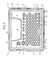
- Fig. 2 is a top view representation of the tape printing apparatus which constitutes the charging system of the embodiment
- Fig. 3 is a left side representation of the tape printing apparatus which constitutes the charging system of the embodiment
- Fig. 4 is a right side representation of the tape printing apparatus which constitutes the charging system of the embodiment
- Fig. 5 is a front side representation of the tape printing apparatus which constitutes the charging system of the embodiment
- Fig. 6 is a rear side representation of the tape printing apparatus which constitutes the charging system of the embodiment
- Fig. 7A is a rear view showing the structure of the tape printing apparatus charger which constitutes the charging system of the embodiment
- Fig. 7B is a plan view showing the structure of the tape printing apparatus charger which constitutes the charging system of the embodiment
- Fig. 7C is a front view showing the structure of the tape printing apparatus charger which constitutes the charging system of the embodiment
- Fig. 8A is a right side view showing the structure of the tape printing apparatus charger which constitutes the charging system of the embodiment
- Fig. 8B is a side sectional view showing the structure of the tape printing apparatus charger which constitutes the charging system of the embodiment;
- Fig. 9 is a perspective view showing an example of mounting the tape printing apparatus into the tape printing apparatus charger, in which the front edge on the front side face section of the tape printing apparatus is placed on the fitting section of the tape printing apparatus charger from obliquely upward of the tape printing apparatus charger;
- Fig. 10 is a side sectional view showing an example of mounting the tape printing apparatus into the tape printing apparatus charger, in which the front side face section of the tape printing apparatus is kept into contact with the top edge of the fitting section of the tape printing apparatus charger and inserted further to the deep side;
- Fig. 11 is a side sectional view showing an example of mounting the tape printing apparatus into the tape printing apparatus charger, in which the tape printing apparatus is inserted to the deep side so that the rib section on the front side face section of the tape printing apparatus rides on the protective rib section erected from the bottom face section of the tape printing apparatus charger;
- Fig. 12 is a side sectional view showing an example of mounting the tape printing apparatus into the tape printing apparatus charger, in which the tape printing apparatus is inserted to the deep side so that the rib section on the front side face section of the tape printing apparatus rides on the protruded section erected from the bottom face section of the tape printing apparatus charger;
- Fig. 13 is a side sectional view showing the tape printing apparatus mounted on the tape printing apparatus charger;
- Fig. 14 is a side sectional view showing an example of inserting the same tape printing apparatus to the deep side and mounting, with the rib section on the front side face section of the tape printing apparatus kept in contact with the front edge section of the tilted guide section of the tape printing apparatus charger;
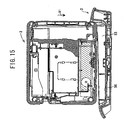
- Fig. 15 is a side sectional view showing an example of loading the tape printing apparatus from substantially just above the tape printing apparatus charger.
- a tape printing apparatus which has a substantially thin, box shape, comprising a key input unit having a plurality of input keys and a display unit disposed on a top face section, a tape discharge slot that discharges a tape on which characters input or edited with the key input unit, or the like, are printed is provided on a first side face section.
- a second side face section, perpendicular to the first side face section, is provided with a charging power receiving terminal.
- the key input unit and display unit are disposed at least within a section at a predetermined distance from each side of a top face section connected to the first side face section.
- a third side face section that opposes the first side face section and the second side face section, and a section thereof outside of the key input unit and display unit is inserted and loaded on the fitting section of the tape printing apparatus charger with the second side face section facing down and recharged in the mounted condition.
- the charging system 1 of this embodiment comprises a tape printing apparatus charger 2 and a tape printing apparatus 3 for charging a secondary battery incorporated therein when the tape printing apparatus 3 is mounted on the tape printing apparatus charger 2.
- the tape printing apparatus charger 2 is provided with a power adaptor, which will be described later, and supplied with electric power from a commercial power supply through this power adaptor to charge the secondary battery in the tape printing apparatus 3.
- the tape printing apparatus can be recharged when the tape printing apparatus is inserted in a fitting section of the tape printing apparatus charger.
- charging is enabled even in a narrow space on a desk, thereby saving installation space for charging.
- the key input unit and the display unit are exposed above the tape printing apparatus charger, key input, editing, and the like, are enabled when the tape printing apparatus is inserted in the tape printing apparatus charger. Still further, because the tape discharge slot is provided in the first side face section perpendicular to the second side face section, tape printing is enabled when the tape printing apparatus is mounted on the tape printing apparatus charger. Because the tape printing apparatus is mounted by inserting a section that is inside a predetermined distance from each side of the top face section and outside of the key input unit and display unit, the vertical width of the section to be inserted into the tape printing apparatus charger decreases. Thus, the tape printing apparatus can be set to the tape printing apparatus charger smoothly from a free angle, such as from an obliquely upward, forward direction. Further, when mounting or removing the tape printing apparatus on/from the tape printing apparatus charger, the tape printing apparatus can be mounted or removed on/from the tape printing apparatus charger easily by gripping its top face section and bottom face section with a single hand.
- a character input keys 5 for inputting text
- a print key 6 for instructing on print of a text
- a space key 7 for converting input characters from one language to another or other letters or inputting a space
- a return key 8 for line feed instruction, executing and selecting of various kinds of processes
- cursor keys 11 for moving a cursor vertically and horizontally on a display 10 which indicates characters, such as letters with several rows and the like, such that they are disposed inside of a predetermined distance from each side of the top face section 4.
- the top face section 4 is disposed outside the tape printing apparatus charger 2 when the tape printing apparatus 3 is loaded on the tape printing apparatus charger 2 as shown in Fig. 1.
- the left side face section 13 of the tape printing apparatus 3 has a tape discharge slot 14 for discharging a printed tape.
- the right side face section 17 of the tape printing apparatus 3 has an adapter connector 18 on which a power adaptor (not shown) is attached, a connector 19 to which a USB cable for connecting with a personal computer (not shown) is attached and so-on. Therefore, when the tape printing apparatus 3 is placed on a desk with its top face section 4 upward, the tape printing apparatus 3 can print a tape with the power adaptor inserted into the adapter connector 18 or using the incorporated secondary battery without inserting the power adaptor.
- a rib 27, which is substantially semi-circular in terms of its side section, is formed from the deep side of the tape discharge slot 14 of the left side face section 13 to the right side face section 17 through the deep side face section 26 at a central position in the thickness direction (vertical direction in Figs. 3 to 6) of the outer vicinity section of the tape printing apparatus 3 and both the right and left comers are formed substantially circularly as seen from the top.
- a rib 28, which is substantially semi-circular in terms of its side section, is formed on the comer sections from the front side section of the right side face section 17 to the right side section of the front side face section 21 such that it is formed semi-circularly as seen from the top and erected outwardly.
- the respective ribs 27-29 are provided such that they are erected in substantially the same height from the side face sections 13, 17, 21, 26.
- a rib 30, which is laterally long and rectangular as seen from the front, is provided on the front side face section 21 of the tape printing apparatus 3 such that it is erected surrounding the front side face section 21 between the respective ribs 28 and 29.
- the rib 30 is formed in a height of their top ends lower than that of the ribs 28, 29.
- Ribs 32, 33 which are substantially triangular in terms of the side view, are provided in sections above the respective ribs 28, 29 on both right and left sides of the rib 30 such that they are protruded in substantially the same height as the protruding heights of the ribs 28, 29.
- Substantially semi-circular protrusions 34 are provided on the right and left comers bottom of the rib 30 laterally long rectangular as seen from the front such that they are protruded in substantially the same height as the protruding height of the ribs 28, 29.
- a rib 36 which is substantially square as seen from the front, is provided around the negative electrode side charging power receiving terminal 23 on the front side face section 21 such that they are protruded in substantially the same height as the protruding height of the ribs 28, 29. Extending sections 36A are provided at a position which divides the charging power receiving terminal 23 in the vertical direction on the inside faces of the rib 36 such that they are extended inwardly.
- a rib 38 which is substantially square in terms of its front view, is protruded in substantially the same height as the protruding height of the ribs 28, 29 so that a groove section 37, which is substantially square in terms of its front view, is formed outside the rib 36.
- Substantially cylindrical bosses 42 for pressing a detection switch 77 (see Fig. 8B) of the tape printing apparatus charger 2 are provided in the center in the thickness direction (vertical direction in Fig. 5) at an equal distance from the charging power receiving terminal 23, between the respective ribs 28/29 and the negative electrode side charging power receiving terminal 23 on the front side face section 21 such that they are protruded in substantially the same height as the protruding height of the respective ribs 28, 29.
- Ribs 43 which are vertically long and rectangular as seen from the front, are provided around the respective bosses 42 such that they are protruded in substantially the same height as the protruding height of the respective ribs 28, 29.
- a tape printing apparatus charger comprising a case having a fitting section, in which a tape printing apparatus which has a substantially thin, box shape is fit, and charging power supply terminals provided in the fitting section for charging the tape printing apparatus when the tape printing apparatus is loaded on the fitting section.
- the fitting section is constituted of a bottom face section having a substantially elongated rectangle shape, on which a predetermined side face section of the tape printing apparatus is to be mounted.
- the fitting section also has a first supporting section, having a substantially elongated rectangle shape, which is formed of wall sections having a predetermined height from four sides of the bottom face section for supporting a section of the predetermined side face section of the tape printing apparatus.
- a second supporting section which is extended upward in a predetermined first length from the top edge of a short side of the first supporting section is provided for supporting one side face section perpendicular to the predetermined side face section of the tape printing apparatus.
- Third supporting sections which are extended in a predetermined second length from right and left side edges of the second supporting section along the top edge of each long side of the first supporting section, are provided for supporting sections in the vicinity of the second supporting section of a top face section and bottom face section of the tape printing apparatus.
- the charging power supply terminals are provided at a predetermined position in the bottom face section.
- the case is formed in the form of a substantially elongated rectangle, as seen in its plan view, of substantially the same size as the first supporting section.
- the tape printing apparatus charger 2 comprises a lower case 51, which has a substantially elongated rectangle shape as seen from the top while its top face section is open, an upper case 52 which is fit to the top face section of the lower case 51 and in which the tape printing apparatus 3 is mounted on a fitting section 53 having a substantially elongated rectangle shape as seen from the top, and a charging circuit section 54 which is accommodated in a backward section of the lower case 51.
- the fitting section 53 in the upper case 52 is constituted of a bottom face section 56, which has a substantially elongated rectangle shape as seen from the top and is substantially the same size as the front side face section 21 of the tape printing apparatus 3.
- the fitting section 53 has respective side wall sections 57A, 57B, 57C, 57D formed with a predetermined height from four sides of the bottom face section 56 and supporting the outer vicinity section below the space key 7, return key 8, respective cursor keys 11, and the like, of the tape printing apparatus 3 when the tape printing apparatus 3 is loaded with its front side face section 21 facing downward.
- the side wall section 57A on the front side is formed such that it is inclined at a predetermined angle outward (about 20 to 30 degrees with respect to a vertical direction, preferably about 25 degrees according to this embodiment) as shown in Fig. 8B.
- An extending section 58 which has substantially the same height as the side wall section 57C and is extended upward, is formed on a top edge section of the side wall section 57C on the deep side (upper in Fig. 7B).
- Extending sections 59 which are extended along the top edge of each of the right and left side wall sections 57B, 57D from the right and left side edge sections of the extending section 58, are provided to support the top face section 4 located outward of the cursor key 11 of the printing apparatus 3 and the like, and the bottom face section opposing the top face section 4 when the tape printing apparatus 3 is loaded with its front side face section 21 facing downward.
- a guide rib 61 which makes contact with the top face section 4 and the bottom face section 56 of the tape printing apparatus 3 when the tape printing apparatus 3 is loaded in the fitting section 53, is provided on each extending section 59 of each of the right and left side wall sections 57B, 57D such that guide rib 61 is erected inwardly.
- a cover section 62 for covering the lower case 51 is formed on the top edge section of each of the right and left side wall sections 57B, 57D and the extending sections 58, 59 such that the cover section 62 is extended substantially at a right angle in an outward direction.
- a tilted guide section 63 is extended outward such that it is tilted downward from the top edge section of the front side wall section 57A, (see Fig. 8A) so that the tilted guide section 63 covers the top face section of the tilted supporting section 64 which is extended outward such that tilted supporting section 64 is tilted downward from the top edge section of the front side face section of the lower case 51.
- a rib 65 is formed such that the rib 65 is extended forward along both of the right and the left side edge of the tilted supporting section 64 from the both of the right and the left side edge sections of the front side face section of the lower case 51 so as to increase the bending strength of the tilted supporting section 64.
- An adapter connector 67 which a power adaptor is to be attached to, is provided on the rear side face section of the lower case 51 and connected to the charging circuit 54.
- Four open holes 69 are made symmetrically along the width direction (right and left direction in Fig. 7B) in the center in the length direction (vertical direction in Fig. 7B) of the bottom face section 56 of the fitting section 53 in the upper case 52.
- Two negative electrode side charging power supply terminals 71 which are connected to the charging circuit section 54, are protruded through the two open holes 69 located in the center, which oppose the charging power receiving terminals 23 of the tape printing apparatus 3, such that they are protruded from the bottom face.
- Two positive electrode side charging power supply terminals 72 which are to be connected to the charging circuit section 54, are protruded through the two open holes 69 located outside, which oppose the charging power receiving terminals 24 of the tape printing apparatus 3, such that they are protruded from the bottom face section 56.
- the charging power supply terminals 71, 72 are formed of a coil spring 73. An end section thereof functions as a torsion coil spring as shown in Fig. 8B and the other end of this coil spring is fixed to the bottom face section 56 to urge each of the charging power supply terminals 71, 72 upward.
- a protective rib 75 having a substantially square shape as seen in terms of top view, which is to be inserted into the groove section 37 formed in the central section of the front side face section 21 of the tape printing apparatus 3, is provided around the negative electrode side charging power supply terminal 71 such that it is erected higher than the protruding height of each charging power supply terminal 71, so as to isolate from the charging power supply terminal 72.
- a laterally long rectangular protruded section 76 which is long in the width direction as seen in plan view and to be engaged in the rib 43 formed in the front side face section 21 of the tape printing apparatus 3, is provided at the central position in the length direction (vertical direction in Fig. 7B) defined by the charging power supply terminal 71 and side wall section 57C on the deep side and in the center in the width direction (right and left direction in Fig. 7B) such that it is protruded up to substantially the same height as the height of the protective rib 75. Further, a through hole 78 is made at the central position of this protruded section 76 so that the boss 42 erected from the front side face section 21 of the tape printing apparatus 3 is capable of being inserted into the same through hole 78.
- the detecting switch 77 is installed on the bottom face section through this through hole 78 and when the detecting switch 77 is pressed by the boss 42 provided on the front side face section 21 of the tape printing apparatus 3, the charging circuit section 54 is driven.
- a power adaptor (not shown) is connected to the adapter connector 67 in the tape printing apparatus charger 2 and the charger is placed on a desk (for example, a narrow gap between a personal computer and a book) with the tilted guide section 63 located forward.
- the top face section 4 and bottom face section of the tape printing apparatus 3 are carried with the hand such that its right side face section 17 is located in the forward direction and then, the bottom edge of the right side face section 17 of the tape printing apparatus 3 is engaged with a forward section (in the direction of an arrow 81) of the fitting section 53 from obliquely upward of the front section of the tape printing apparatus charger 2.
- the front side face section 21 of the tape printing apparatus 3 is brought into a contact with the top edge of the side wall section 57A on the front side of the fitting section 53 in the tape printing apparatus charger 2 and with the rib 28 formed on the bottom edge section of the right side face section 17 of the tape printing apparatus 3 kept in contact with the bottom face section 56 of the fitting section 53, this tape printing apparatus 3 is inserted in the direction of the front side (direction of an arrow 82).
- the tape printing apparatus 3 is inserted in the direction of the front side (direction of an arrow 83) with the front side face section 21 of the tape printing apparatus 3 kept in contact with the top edge section of the side wall section 57A on the front side of the fitting section 53 in the tape printing apparatus 3. Consequently, the rib 28 formed on the bottom edge section of the right side face section 17 of the tape printing apparatus 3 rides on the protective rib 75 erected on the bottom face section 56 of the fitting section 53. As a result, the front side face section 21 of the tape printing apparatus 3 is blocked from being in a direct contact with the charging power supply terminals 71, 72.
- the tape printing apparatus 3 is inserted in the direction of the front side (direction of the arrow 84) with the front side face section 21 of the tape printing apparatus 3 kept in contact with the top edge section of the side wall section 57A on the front side of the fitting section 53 of the tape printing apparatus charger 2. Consequently, the rib 28 formed on the front edge section of the front side face section 21 of the tape printing apparatus 3 rides on the protruded section 76 erected from the bottom face section 56 of the fitting section 53. As a result, the front side face section 21 of the tape printing apparatus 3 is blocked from making a direct contact with the detecting switch 77.
- the front side face section 21 of the tape printing apparatus 3 is mounted on the bottom face section 56 of the fitting section 53 in the tape printing apparatus charger 2.
- An outer vicinity section below the space key 7, the return key 8 and respective cursor keys 11 and the like of the tape printing apparatus 3, the bottom face section of the right side face section 17, and a section in the vicinity of both side edges on the bottom of the right side face section 17 are supported by the respective side wall sections 57A, 57B, 57C and 57D of the fitting section 53 of the tape printing apparatus charger 2, the extending section 58 and the extending sections 59 (see Fig. 1).
- characters, and the like may be printed on a tape by connecting the tape printing apparatus 3 to a personal computer (not shown) and inputting the characters through the character input key 5.
- the printed tape is then discharged through the tape discharge slot 14 located on the front side of the tape printing apparatus 3.
- the tape printing apparatus 3 can be mounted on the fitting section 53 of the tape printing apparatus charger 2 in the same procedure as indicated in Figs. 9-13 and recharged because the charging power receiving terminals 23, 24 of the tape printing apparatus 3 are provided at the central position in the length direction (right and left direction in Fig. 13) of the front side face section 21 and the respective bosses 42 are formed at an equal distance from each of the charging power receiving terminals 23, 24 and at the central position in the width direction.
- this tape printing apparatus charger can be easily installed in a narrow or small space on a desk, thereby saving desk space. Further, because the first supporting section of the tape printing apparatus charger is formed to have a predetermined height from four sides of the bottom face section of the fitting section for supporting the section of the predetermined side face section of the tape printing apparatus, the depth of the fitting section can be decreased and the height of the tape printing apparatus charger can be reduced. Consequently, the tape printing apparatus can be set easily to the tape printing apparatus charger from a free angle, such as from an obliquely upward, forward direction, for example.
- the tape printing apparatus is loaded from the forward direction with the second supporting section and third supporting section of the tape printing apparatus charger located on the deep side, the side face section on the deep side perpendicular to the predetermined side face section of the tape printing apparatus and the top face section and bottom face section in the vicinity of the side face section on the deep side are supported by the second supporting section and third supporting section of the tape printing apparatus charger. Consequently, the tape printing apparatus is supported stably and can be set to the tape printing apparatus charger from a free angle, such as from an obliquely upward, forward direction. Additionally, because the charging power supply terminals of the tape printing apparatus charger are provided at a predetermined position in the bottom face section of the fitting section, the tape printing apparatus can be mounted securely in the fitting section to ensure complete charging.
- the tape printing apparatus 3 As shown in Fig. 14, with the tape printing apparatus 3 lifted slightly up from a desk top, the rib 28 of the front side face section 21 of the tape printing apparatus 3 is kept in contact with the tilted guide section 63 on the front side of the tape printing apparatus charger 2 and the tape printing apparatus 3 is inserted in the direction to the deep side (directions of arrows 87, 88, 89), the tape printing apparatus 3 can be mounted on the fitting section 53 in the tape printing apparatus charger 2. Further, even if the tape printing apparatus 3 is reversed in its mounting direction, the tape printing apparatus 3 can be mounted on the fitting section 53 of the tape printing apparatus charger 2 in the same procedure as described in Fig.
- the charging power receiving terminals 23, 24 of the tape printing apparatus 3 are provided at the central position in the length direction (right and left direction in Fig. 14) of the front side face section 21 and the respective bosses 42 are formed at an equal distance in the length direction from the charging power receiving terminals 23, 24 and at the central position in the width direction.
- the tape printing apparatus 3 is engaged downward (direction of an arrow 91) from just above the fitting section 53 of the tape printing apparatus charger 2, the tape printing apparatus 3 can be loaded on the fitting section 53 in the tape printing apparatus charger 2.
- the fitting section 53 of the tape printing apparatus charger 2 is formed in a substantially elongated rectangle configuration as seen from above, which is substantially the same configuration as the front side face section 21 of the tape printing apparatus 3.
- the tape printing apparatus can be recharged when it is stood on the tape printing apparatus charger 2 with the front side face section 21 of the tape printing apparatus 3, which is substantially thin and box shaped, is in a downward orientation.
- the tape printing apparatus 3 can be recharged by installing the tape printing apparatus 3 onto the tape printing apparatus charger 2.
- the tape printing apparatus 3 allows key input, editing functions, and the like, when the tape printing apparatus 3 is stood on the tape printing apparatus charger 2. Further, because the tape discharge slot 14 of the tape printing apparatus 3 is provided in the left side face section 13, the tape printing apparatus is capable of printing on a tape when the tape printing apparatus 3 is loaded on the tape printing apparatus charger 2.
- the respective side wall sections 57A, 57B, 57C and 57D of the tape printing apparatus charger 2 in the charging system 1 are formed to a predetermined height, so as to support the vicinity section of the front side face section 21 of the tape printing apparatus 3 with four sides of the bottom face section 56 of the fitting section 53, the depth of the fitting section 53 can be reduced and at the same time, the height of the tape printing apparatus charger 2 can be reduced, so that the tape printing apparatus 3 can be loaded easily into the tape printing apparatus charger 2.
- the tape printing apparatus 3 can be loaded on the tape printing apparatus charger 2 by inserting a section of the tape printing apparatus 3 within a predetermined distance from each side of the top face section 4 and outside of the character input key 5, the print key 6, the space key 7, the return key 8, and the cursor key 11 into the tape printing apparatus charger 2, the tape printing apparatus 3 can be set smoothly on the tape printing apparatus charger 2 at a free angle such as from obliquely upward, forward direction.
- the tape printing apparatus 3 can be mounted or removed on/from the tape printing apparatus charger 2 easily.
- the tape printing apparatus 3 If with the respective extending sections 58, 59 of the tape printing apparatus charger 2 located on the deep side, the tape printing apparatus 3 is loaded from the forward side, the right side face section 17 of the tape printing apparatus 3 and the top face section 4 or the bottom face section 56 of the tape printing apparatus 3 in the vicinity of the right side face section 17 are supported by the respective extending sections 58, 59.
- the tape printing apparatus 3 can be supported stably and can be set from a free angle such as obliquely upward, forward direction.
- the tape printing apparatus 3 can be recharged securely when it is loaded in the fitting section 53 of the tape printing apparatus charger 2.
- the tape printing apparatus 3 is inserted into the tape printing apparatus charger 2 from obliquely upward or from the forward direction, such that the rib 28, makes engaging contact with the tape printing apparatus charger 2 and slides on the tape printing apparatus charger 2 so that it is loaded smoothly.
- the tape printing apparatus 3 can be set on the tape printing apparatus charger 2 smoothly at a free angle, such as from obliquely upward, from forward direction, for example.
- the tape printing apparatus 3 can be stood securely with the front side face section 21 down, thereby improving the stability when the tape printing apparatus 3 is loaded on the tape printing apparatus charger 2.
- the charging power receiving terminals 23, 24 of the tape printing apparatus 3 are provided along the thickness direction at the central position in the length direction of the front side face section 21 and the charging power supply terminals 71, 72 of the tape printing apparatus charger 2 are provided along the direction of the short side at the central position in the length direction of the bottom face section 56 of the fitting section 53, on which the tape printing apparatus 3 is to be loaded, when the tape printing apparatus 3 is loaded on the tape printing apparatus charger 2 with the front side face section 21 down, the tape printing apparatus 3 can be mounted on the tape printing apparatus charger 2 even if the left side face section 13 and the right side face section 17 of the tape printing apparatus 3 are reversed in the back and forth direction, so that the tape printing apparatus 3 can be loaded on the tape printing apparatus charger 2 smoothly.
- the tape printing apparatus 3 can be set from slightly below an entrance of the fitting section 53 in the tape printing apparatus charger 2, the tape printing apparatus 3 can be set from a free angle even if the tape printing apparatus charger 2 placed in a small space on a user's desk.
- the detecting switch 77 is disposed on the side of the extending sections 58, 59 with respect to the charging power supply terminals 71, 72 on the bottom face section 56 of the fitting section 53, if the tape printing apparatus is placed on a desk with the extending sections 58, 59 on the deep side and the tape printing apparatus 3 is loaded from the front side, the rib 28 on the deep side of the front side face section 21 of the tape printing apparatus 3 never contacts the detecting switch 77 until it rides over the charging power supply terminals 71, 72, even if it makes contact with the bottom face section 56 of the fitting section 53. Thus, when loading the tape printing apparatus 3 onto the fitting section 53, the apparatus 3 is never caught by anything and can be loaded on the tape printing apparatus charger 2 smoothly.
- the front side face section 21 of the tape printing apparatus 3 rides over the charging power supply terminals 71, 72.
- a short circuit caused by a metal piece, such as clip between the charging power supply terminals 71 and 72 of the tape printing apparatus charger 2 can be avoided.
- the protective rib 75 is provided higher than the protruding height of the charging power supply terminals 71 around the respective charging power supply terminals 71 on a negative electrode side, a short circuit caused by a metal piece, such as clip between the charging power supply terminals 71 and 72, can be avoided. Further, even if the tape printing apparatus 3 is loaded in a position deviated from a horizontal direction, a short circuit by the charging power receiving terminals 23, 24 of the tape printing apparatus 3 can be prevented because the charging power supply terminals 71, 72 on the tape printing apparatus charger 2 are isolated by the protective ribs 75.
- the invention is not limited to this exemplary embodiment but needless to say, the present invention may be improved or modified in various ways within a range not departing from the gist of the invention.
Landscapes
- Printers Characterized By Their Purpose (AREA)
- Charge And Discharge Circuits For Batteries Or The Like (AREA)
- Handling Of Sheets (AREA)
- Sheets, Magazines, And Separation Thereof (AREA)
- Controlling Sheets Or Webs (AREA)
Applications Claiming Priority (2)
| Application Number | Priority Date | Filing Date | Title |
|---|---|---|---|
| JP2003330850 | 2003-09-24 | ||
| JP2003330850A JP3938125B2 (ja) | 2003-09-24 | 2003-09-24 | テープ印字装置、充電器及び充電システム |
Publications (2)
| Publication Number | Publication Date |
|---|---|
| EP1518697A1 true EP1518697A1 (de) | 2005-03-30 |
| EP1518697B1 EP1518697B1 (de) | 2010-04-14 |
Family
ID=34191435
Family Applications (1)
| Application Number | Title | Priority Date | Filing Date |
|---|---|---|---|
| EP04021548A Expired - Lifetime EP1518697B1 (de) | 2003-09-24 | 2004-09-10 | Streifendruckgerät, Streifendruckgerätlader und Streifendruckgerätladesystem |
Country Status (6)
| Country | Link |
|---|---|
| US (2) | US7153051B2 (de) |
| EP (1) | EP1518697B1 (de) |
| JP (1) | JP3938125B2 (de) |
| CN (1) | CN1321824C (de) |
| AT (1) | ATE464187T1 (de) |
| DE (1) | DE602004026518D1 (de) |
Families Citing this family (12)
| Publication number | Priority date | Publication date | Assignee | Title |
|---|---|---|---|---|
| JP2006192777A (ja) * | 2005-01-14 | 2006-07-27 | Seiko Epson Corp | テープ印刷装置 |
| US9434191B2 (en) | 2010-04-12 | 2016-09-06 | Zih Corp. | Label peeling, universal printheads and related methods |
| WO2011130319A1 (en) | 2010-04-12 | 2011-10-20 | Zih Corp. | Mobile printer networking and interfacing |
| JP5601530B2 (ja) * | 2011-03-31 | 2014-10-08 | ブラザー工業株式会社 | 印刷装置 |
| USD700649S1 (en) * | 2012-10-15 | 2014-03-04 | Ross Kimble | Label printing device |
| JP2016028879A (ja) * | 2014-07-14 | 2016-03-03 | セイコーエプソン株式会社 | 充電装置および充電システム |
| JP6537856B2 (ja) * | 2015-03-13 | 2019-07-03 | 富士通コンポーネント株式会社 | 電子装置、給電装置及び電子装置システム |
| EP3661757A4 (de) * | 2017-07-31 | 2021-03-03 | Hewlett-Packard Development Company, L.P. | Verwendung von entladener energie |
| US10987942B2 (en) * | 2018-02-01 | 2021-04-27 | Fujitsu Component Limited | Printing apparatus |
| JP6764154B2 (ja) * | 2018-05-23 | 2020-09-30 | Necプラットフォームズ株式会社 | 携帯端末の充電台 |
| JP7602721B2 (ja) * | 2020-12-28 | 2024-12-19 | ブラザー工業株式会社 | 保持台、印刷装置、及び印刷装置保持体 |
| US12285959B2 (en) | 2022-04-06 | 2025-04-29 | David AMEGASHIE | Ultra-thin portable printer |
Citations (2)
| Publication number | Priority date | Publication date | Assignee | Title |
|---|---|---|---|---|
| JPS6460232A (en) | 1987-08-31 | 1989-03-07 | Matsushita Electric Industrial Co Ltd | Charging apparatus |
| US20020186293A1 (en) * | 2001-06-11 | 2002-12-12 | Masahiro Ando | Portable electronic device with printing mechanism |
Family Cites Families (22)
| Publication number | Priority date | Publication date | Assignee | Title |
|---|---|---|---|---|
| US5144217A (en) * | 1989-03-03 | 1992-09-01 | Black & Decker Inc. | Cordless tool battery housing and charging system |
| US5331580A (en) * | 1989-01-31 | 1994-07-19 | Norand Corporation | Data capture system with communicating and recharging docking apparatus, and modular printer and hand-held data terminal means cooperable therewith |
| US5186558A (en) * | 1990-11-21 | 1993-02-16 | Norand Corporation | Portable printer with receptacle for data communication terminal |
| JP2503137B2 (ja) * | 1991-10-30 | 1996-06-05 | 富士通株式会社 | 携帯電話機用充電器構造 |
| US5209583A (en) * | 1992-04-01 | 1993-05-11 | Telxon Corporation | Compact printer for portable computer |
| JP3416962B2 (ja) * | 1992-09-18 | 2003-06-16 | ソニー株式会社 | バッテリーパック |
| CA2107746A1 (en) * | 1992-10-06 | 1994-04-07 | Masahiko Nunokawa | Tape printing device and tape cartridge used therein |
| KR100268568B1 (ko) * | 1993-09-21 | 2000-10-16 | 소가 마사히로 | 오실로스코프의 하우징 구조체 |
| US5411339A (en) * | 1993-12-09 | 1995-05-02 | Kroy, Inc. | Portable printer and cartridge therefor |
| JP3249290B2 (ja) | 1994-04-27 | 2002-01-21 | 三洋電機株式会社 | 二次電池を内蔵する電池機器と充電器 |
| DE69634884T2 (de) * | 1995-04-11 | 2006-04-27 | Canon K.K. | Tintenstrahlaufzeichnungsgerät mit einem Bildlesekopf |
| EP0761454B1 (de) * | 1995-08-25 | 1999-10-06 | Esselte N.V. | Banddruckgerät |
| US5848401A (en) * | 1995-12-22 | 1998-12-08 | Goldberg; Robert M. | Hand-held portable postage meter that uses pre-printed tape |
| JP3733239B2 (ja) * | 1998-04-15 | 2006-01-11 | キヤノン株式会社 | 記録装置 |
| US6075341A (en) * | 1999-02-17 | 2000-06-13 | Black & Decker Inc. | Power pack charging system for a power tool |
| US6241407B1 (en) * | 1999-09-16 | 2001-06-05 | Monarch Marking Systems, Inc. | Portable printer |
| DE29922706U1 (de) * | 1999-12-23 | 2000-04-06 | Tempa Communication Inc., Hsin-tien, Taipeh | Batterieladegerät für ein Mobiltelefon |
| JP3871508B2 (ja) * | 2000-11-15 | 2007-01-24 | 株式会社荏原製作所 | 基板搬送容器の給電装置 |
| US6610941B2 (en) * | 2001-10-02 | 2003-08-26 | Jdp Innovations Inc. | Battery size detector for a battery charger |
| JP3678188B2 (ja) * | 2001-10-09 | 2005-08-03 | ソニー株式会社 | バッテリパック充電装置 |
| US6847190B2 (en) * | 2002-02-26 | 2005-01-25 | Linvatec Corporation | Method and apparatus for charging sterilizable rechargeable batteries |
| US6776542B1 (en) * | 2003-03-28 | 2004-08-17 | Keith Kearney | Ticket issuing system |
-
2003
- 2003-09-24 JP JP2003330850A patent/JP3938125B2/ja not_active Expired - Fee Related
-
2004
- 2004-08-27 US US10/927,144 patent/US7153051B2/en not_active Expired - Lifetime
- 2004-09-10 DE DE602004026518T patent/DE602004026518D1/de not_active Expired - Lifetime
- 2004-09-10 EP EP04021548A patent/EP1518697B1/de not_active Expired - Lifetime
- 2004-09-10 AT AT04021548T patent/ATE464187T1/de not_active IP Right Cessation
- 2004-09-21 CN CNB2004100119252A patent/CN1321824C/zh not_active Expired - Fee Related
-
2006
- 2006-11-17 US US11/600,726 patent/US7435026B2/en not_active Expired - Fee Related
Patent Citations (2)
| Publication number | Priority date | Publication date | Assignee | Title |
|---|---|---|---|---|
| JPS6460232A (en) | 1987-08-31 | 1989-03-07 | Matsushita Electric Industrial Co Ltd | Charging apparatus |
| US20020186293A1 (en) * | 2001-06-11 | 2002-12-12 | Masahiro Ando | Portable electronic device with printing mechanism |
Non-Patent Citations (1)
| Title |
|---|
| PATENT ABSTRACTS OF JAPAN vol. 1996, no. 03 29 March 1996 (1996-03-29) * |
Also Published As
| Publication number | Publication date |
|---|---|
| US20070065221A1 (en) | 2007-03-22 |
| DE602004026518D1 (de) | 2010-05-27 |
| US7153051B2 (en) | 2006-12-26 |
| US7435026B2 (en) | 2008-10-14 |
| EP1518697B1 (de) | 2010-04-14 |
| ATE464187T1 (de) | 2010-04-15 |
| CN1321824C (zh) | 2007-06-20 |
| US20050063751A1 (en) | 2005-03-24 |
| JP2005102372A (ja) | 2005-04-14 |
| CN1600556A (zh) | 2005-03-30 |
| JP3938125B2 (ja) | 2007-06-27 |
Similar Documents
| Publication | Publication Date | Title |
|---|---|---|
| US7153051B2 (en) | Tape printing apparatus, tape printing apparatus charger and tape printing apparatus charging system | |
| US7151356B1 (en) | Retractable cord power adapter and battery pack | |
| US5059885A (en) | Battery charger with battery positioning and support apparatus | |
| CA2187584C (en) | Battery charger | |
| US7830116B2 (en) | Mobile electronic equipment and battery charger cradle | |
| JP4462112B2 (ja) | 電動工具 | |
| AU630742B2 (en) | Battery charger housing for batteries of differing dimensions | |
| EP0778627A1 (de) | Batteriesatz | |
| US20120177967A1 (en) | Battery case for portable electronic devices | |
| EP0572189A1 (de) | Batterieladegerät für ein schnurloses Telefon | |
| US20090315511A1 (en) | Charging system and charging apparatus thereof | |
| KR100425094B1 (ko) | 휴대용 단말기의 배터리 팩 착탈 구조 | |
| JP3089830B2 (ja) | バッテリパック | |
| US20080143294A1 (en) | Universal battery charger with adjustable pocket | |
| CN209805462U (zh) | 一种带数据线的移动电源 | |
| US20020182486A1 (en) | Battery cover for charging | |
| US6403254B1 (en) | Battery means for hand held electronic devices | |
| CN221240145U (zh) | 相机电池充电装置 | |
| JP6764154B2 (ja) | 携帯端末の充電台 | |
| JP3999892B2 (ja) | 充電器 | |
| JP3731836B2 (ja) | 充電用置き台 | |
| US11750028B2 (en) | Wireless charging device having an inclined surface to receive a charging rack | |
| US7121851B1 (en) | System and method for multi-positional power supply adaptor | |
| CN212304809U (zh) | 移动电源组件 | |
| JP2001224136A (ja) | 充電器 |
Legal Events
| Date | Code | Title | Description |
|---|---|---|---|
| PUAI | Public reference made under article 153(3) epc to a published international application that has entered the european phase |
Free format text: ORIGINAL CODE: 0009012 |
|
| AK | Designated contracting states |
Kind code of ref document: A1 Designated state(s): AT BE BG CH CY CZ DE DK EE ES FI FR GB GR HU IE IT LI LU MC NL PL PT RO SE SI SK TR |
|
| AX | Request for extension of the european patent |
Extension state: AL HR LT LV MK |
|
| 17P | Request for examination filed |
Effective date: 20050223 |
|
| AKX | Designation fees paid |
Designated state(s): AT BE BG CH CY CZ DE DK EE ES FI FR GB GR HU IE IT LI LU MC NL PL PT RO SE SI SK TR |
|
| GRAP | Despatch of communication of intention to grant a patent |
Free format text: ORIGINAL CODE: EPIDOSNIGR1 |
|
| GRAS | Grant fee paid |
Free format text: ORIGINAL CODE: EPIDOSNIGR3 |
|
| GRAA | (expected) grant |
Free format text: ORIGINAL CODE: 0009210 |
|
| AK | Designated contracting states |
Kind code of ref document: B1 Designated state(s): AT BE BG CH CY CZ DE DK EE ES FI FR GB GR HU IE IT LI LU MC NL PL PT RO SE SI SK TR |
|
| REG | Reference to a national code |
Ref country code: GB Ref legal event code: FG4D |
|
| REG | Reference to a national code |
Ref country code: CH Ref legal event code: EP |
|
| REG | Reference to a national code |
Ref country code: IE Ref legal event code: FG4D |
|
| REF | Corresponds to: |
Ref document number: 602004026518 Country of ref document: DE Date of ref document: 20100527 Kind code of ref document: P |
|
| REG | Reference to a national code |
Ref country code: NL Ref legal event code: VDEP Effective date: 20100414 |
|
| PG25 | Lapsed in a contracting state [announced via postgrant information from national office to epo] |
Ref country code: SE Free format text: LAPSE BECAUSE OF FAILURE TO SUBMIT A TRANSLATION OF THE DESCRIPTION OR TO PAY THE FEE WITHIN THE PRESCRIBED TIME-LIMIT Effective date: 20100414 Ref country code: NL Free format text: LAPSE BECAUSE OF FAILURE TO SUBMIT A TRANSLATION OF THE DESCRIPTION OR TO PAY THE FEE WITHIN THE PRESCRIBED TIME-LIMIT Effective date: 20100414 Ref country code: ES Free format text: LAPSE BECAUSE OF FAILURE TO SUBMIT A TRANSLATION OF THE DESCRIPTION OR TO PAY THE FEE WITHIN THE PRESCRIBED TIME-LIMIT Effective date: 20100725 |
|
| PG25 | Lapsed in a contracting state [announced via postgrant information from national office to epo] |
Ref country code: AT Free format text: LAPSE BECAUSE OF FAILURE TO SUBMIT A TRANSLATION OF THE DESCRIPTION OR TO PAY THE FEE WITHIN THE PRESCRIBED TIME-LIMIT Effective date: 20100414 Ref country code: SI Free format text: LAPSE BECAUSE OF FAILURE TO SUBMIT A TRANSLATION OF THE DESCRIPTION OR TO PAY THE FEE WITHIN THE PRESCRIBED TIME-LIMIT Effective date: 20100414 Ref country code: FI Free format text: LAPSE BECAUSE OF FAILURE TO SUBMIT A TRANSLATION OF THE DESCRIPTION OR TO PAY THE FEE WITHIN THE PRESCRIBED TIME-LIMIT Effective date: 20100414 |
|
| PG25 | Lapsed in a contracting state [announced via postgrant information from national office to epo] |
Ref country code: CY Free format text: LAPSE BECAUSE OF FAILURE TO SUBMIT A TRANSLATION OF THE DESCRIPTION OR TO PAY THE FEE WITHIN THE PRESCRIBED TIME-LIMIT Effective date: 20100421 Ref country code: GR Free format text: LAPSE BECAUSE OF FAILURE TO SUBMIT A TRANSLATION OF THE DESCRIPTION OR TO PAY THE FEE WITHIN THE PRESCRIBED TIME-LIMIT Effective date: 20100715 Ref country code: PL Free format text: LAPSE BECAUSE OF FAILURE TO SUBMIT A TRANSLATION OF THE DESCRIPTION OR TO PAY THE FEE WITHIN THE PRESCRIBED TIME-LIMIT Effective date: 20100414 |
|
| PG25 | Lapsed in a contracting state [announced via postgrant information from national office to epo] |
Ref country code: DK Free format text: LAPSE BECAUSE OF FAILURE TO SUBMIT A TRANSLATION OF THE DESCRIPTION OR TO PAY THE FEE WITHIN THE PRESCRIBED TIME-LIMIT Effective date: 20100414 Ref country code: PT Free format text: LAPSE BECAUSE OF FAILURE TO SUBMIT A TRANSLATION OF THE DESCRIPTION OR TO PAY THE FEE WITHIN THE PRESCRIBED TIME-LIMIT Effective date: 20100816 Ref country code: EE Free format text: LAPSE BECAUSE OF FAILURE TO SUBMIT A TRANSLATION OF THE DESCRIPTION OR TO PAY THE FEE WITHIN THE PRESCRIBED TIME-LIMIT Effective date: 20100414 |
|
| PLBE | No opposition filed within time limit |
Free format text: ORIGINAL CODE: 0009261 |
|
| STAA | Information on the status of an ep patent application or granted ep patent |
Free format text: STATUS: NO OPPOSITION FILED WITHIN TIME LIMIT |
|
| PG25 | Lapsed in a contracting state [announced via postgrant information from national office to epo] |
Ref country code: SK Free format text: LAPSE BECAUSE OF FAILURE TO SUBMIT A TRANSLATION OF THE DESCRIPTION OR TO PAY THE FEE WITHIN THE PRESCRIBED TIME-LIMIT Effective date: 20100414 Ref country code: RO Free format text: LAPSE BECAUSE OF FAILURE TO SUBMIT A TRANSLATION OF THE DESCRIPTION OR TO PAY THE FEE WITHIN THE PRESCRIBED TIME-LIMIT Effective date: 20100414 Ref country code: CZ Free format text: LAPSE BECAUSE OF FAILURE TO SUBMIT A TRANSLATION OF THE DESCRIPTION OR TO PAY THE FEE WITHIN THE PRESCRIBED TIME-LIMIT Effective date: 20100414 |
|
| 26N | No opposition filed |
Effective date: 20110117 |
|
| PG25 | Lapsed in a contracting state [announced via postgrant information from national office to epo] |
Ref country code: IT Free format text: LAPSE BECAUSE OF FAILURE TO SUBMIT A TRANSLATION OF THE DESCRIPTION OR TO PAY THE FEE WITHIN THE PRESCRIBED TIME-LIMIT Effective date: 20100414 |
|
| PG25 | Lapsed in a contracting state [announced via postgrant information from national office to epo] |
Ref country code: MC Free format text: LAPSE BECAUSE OF NON-PAYMENT OF DUE FEES Effective date: 20100930 |
|
| REG | Reference to a national code |
Ref country code: CH Ref legal event code: PL |
|
| PG25 | Lapsed in a contracting state [announced via postgrant information from national office to epo] |
Ref country code: CH Free format text: LAPSE BECAUSE OF NON-PAYMENT OF DUE FEES Effective date: 20100930 Ref country code: IE Free format text: LAPSE BECAUSE OF NON-PAYMENT OF DUE FEES Effective date: 20100910 Ref country code: LI Free format text: LAPSE BECAUSE OF NON-PAYMENT OF DUE FEES Effective date: 20100930 |
|
| PG25 | Lapsed in a contracting state [announced via postgrant information from national office to epo] |
Ref country code: BG Free format text: LAPSE BECAUSE OF FAILURE TO SUBMIT A TRANSLATION OF THE DESCRIPTION OR TO PAY THE FEE WITHIN THE PRESCRIBED TIME-LIMIT Effective date: 20100414 Ref country code: LU Free format text: LAPSE BECAUSE OF NON-PAYMENT OF DUE FEES Effective date: 20100910 Ref country code: HU Free format text: LAPSE BECAUSE OF FAILURE TO SUBMIT A TRANSLATION OF THE DESCRIPTION OR TO PAY THE FEE WITHIN THE PRESCRIBED TIME-LIMIT Effective date: 20101015 |
|
| PG25 | Lapsed in a contracting state [announced via postgrant information from national office to epo] |
Ref country code: TR Free format text: LAPSE BECAUSE OF FAILURE TO SUBMIT A TRANSLATION OF THE DESCRIPTION OR TO PAY THE FEE WITHIN THE PRESCRIBED TIME-LIMIT Effective date: 20100414 |
|
| PG25 | Lapsed in a contracting state [announced via postgrant information from national office to epo] |
Ref country code: BG Free format text: LAPSE BECAUSE OF FAILURE TO SUBMIT A TRANSLATION OF THE DESCRIPTION OR TO PAY THE FEE WITHIN THE PRESCRIBED TIME-LIMIT Effective date: 20100714 |
|
| REG | Reference to a national code |
Ref country code: FR Ref legal event code: PLFP Year of fee payment: 13 |
|
| REG | Reference to a national code |
Ref country code: FR Ref legal event code: PLFP Year of fee payment: 14 |
|
| REG | Reference to a national code |
Ref country code: FR Ref legal event code: PLFP Year of fee payment: 15 |
|
| PGFP | Annual fee paid to national office [announced via postgrant information from national office to epo] |
Ref country code: DE Payment date: 20190813 Year of fee payment: 16 Ref country code: FR Payment date: 20190819 Year of fee payment: 16 |
|
| PGFP | Annual fee paid to national office [announced via postgrant information from national office to epo] |
Ref country code: BE Payment date: 20190815 Year of fee payment: 16 |
|
| PGFP | Annual fee paid to national office [announced via postgrant information from national office to epo] |
Ref country code: GB Payment date: 20190827 Year of fee payment: 16 |
|
| REG | Reference to a national code |
Ref country code: DE Ref legal event code: R119 Ref document number: 602004026518 Country of ref document: DE |
|
| GBPC | Gb: european patent ceased through non-payment of renewal fee |
Effective date: 20200910 |
|
| REG | Reference to a national code |
Ref country code: BE Ref legal event code: MM Effective date: 20200930 |
|
| PG25 | Lapsed in a contracting state [announced via postgrant information from national office to epo] |
Ref country code: DE Free format text: LAPSE BECAUSE OF NON-PAYMENT OF DUE FEES Effective date: 20210401 Ref country code: FR Free format text: LAPSE BECAUSE OF NON-PAYMENT OF DUE FEES Effective date: 20200930 |
|
| PG25 | Lapsed in a contracting state [announced via postgrant information from national office to epo] |
Ref country code: GB Free format text: LAPSE BECAUSE OF NON-PAYMENT OF DUE FEES Effective date: 20200910 Ref country code: BE Free format text: LAPSE BECAUSE OF NON-PAYMENT OF DUE FEES Effective date: 20200930 |