EP1518574B1 - Kanüle zur Abgabe von flüssigen Produkten zur analen und vaginalen Anwendung - Google Patents
Kanüle zur Abgabe von flüssigen Produkten zur analen und vaginalen Anwendung Download PDFInfo
- Publication number
- EP1518574B1 EP1518574B1 EP04021121A EP04021121A EP1518574B1 EP 1518574 B1 EP1518574 B1 EP 1518574B1 EP 04021121 A EP04021121 A EP 04021121A EP 04021121 A EP04021121 A EP 04021121A EP 1518574 B1 EP1518574 B1 EP 1518574B1
- Authority
- EP
- European Patent Office
- Prior art keywords
- cannula
- tubular portion
- plunger
- stem
- cannula according
- Prior art date
- Legal status (The legal status is an assumption and is not a legal conclusion. Google has not performed a legal analysis and makes no representation as to the accuracy of the status listed.)
- Expired - Lifetime
Links
- 239000012530 fluid Substances 0.000 title claims abstract description 12
- 238000004806 packaging method and process Methods 0.000 claims abstract description 11
- 230000000295 complement effect Effects 0.000 claims description 8
- 230000014759 maintenance of location Effects 0.000 claims description 4
- 230000001419 dependent effect Effects 0.000 claims 4
- 238000007789 sealing Methods 0.000 claims 1
- 241001631457 Cannula Species 0.000 description 9
- 239000000463 material Substances 0.000 description 4
- 239000000344 soap Substances 0.000 description 3
- 239000007787 solid Substances 0.000 description 3
- 239000006071 cream Substances 0.000 description 2
- 239000003814 drug Substances 0.000 description 2
- 239000002674 ointment Substances 0.000 description 2
- 210000001215 vagina Anatomy 0.000 description 2
- 238000003466 welding Methods 0.000 description 2
- 238000004026 adhesive bonding Methods 0.000 description 1
- 238000000605 extraction Methods 0.000 description 1
- 230000000670 limiting effect Effects 0.000 description 1
- 229940126601 medicinal product Drugs 0.000 description 1
- 230000004048 modification Effects 0.000 description 1
- 238000012986 modification Methods 0.000 description 1
- 238000002360 preparation method Methods 0.000 description 1
Images

Classifications
-
- A—HUMAN NECESSITIES
- A61—MEDICAL OR VETERINARY SCIENCE; HYGIENE
- A61M—DEVICES FOR INTRODUCING MEDIA INTO, OR ONTO, THE BODY; DEVICES FOR TRANSDUCING BODY MEDIA OR FOR TAKING MEDIA FROM THE BODY; DEVICES FOR PRODUCING OR ENDING SLEEP OR STUPOR
- A61M31/00—Devices for introducing or retaining media, e.g. remedies, in cavities of the body
-
- A—HUMAN NECESSITIES
- A61—MEDICAL OR VETERINARY SCIENCE; HYGIENE
- A61M—DEVICES FOR INTRODUCING MEDIA INTO, OR ONTO, THE BODY; DEVICES FOR TRANSDUCING BODY MEDIA OR FOR TAKING MEDIA FROM THE BODY; DEVICES FOR PRODUCING OR ENDING SLEEP OR STUPOR
- A61M3/00—Medical syringes, e.g. enemata; Irrigators
- A61M3/02—Enemata; Irrigators
- A61M3/0279—Cannula; Nozzles; Tips; their connection means
-
- A—HUMAN NECESSITIES
- A61—MEDICAL OR VETERINARY SCIENCE; HYGIENE
- A61M—DEVICES FOR INTRODUCING MEDIA INTO, OR ONTO, THE BODY; DEVICES FOR TRANSDUCING BODY MEDIA OR FOR TAKING MEDIA FROM THE BODY; DEVICES FOR PRODUCING OR ENDING SLEEP OR STUPOR
- A61M25/00—Catheters; Hollow probes
- A61M25/01—Introducing, guiding, advancing, emplacing or holding catheters
- A61M2025/0175—Introducing, guiding, advancing, emplacing or holding catheters having telescopic features, interengaging nestable members movable in relations to one another
-
- A—HUMAN NECESSITIES
- A61—MEDICAL OR VETERINARY SCIENCE; HYGIENE
- A61M—DEVICES FOR INTRODUCING MEDIA INTO, OR ONTO, THE BODY; DEVICES FOR TRANSDUCING BODY MEDIA OR FOR TAKING MEDIA FROM THE BODY; DEVICES FOR PRODUCING OR ENDING SLEEP OR STUPOR
- A61M25/00—Catheters; Hollow probes
- A61M25/01—Introducing, guiding, advancing, emplacing or holding catheters
- A61M25/06—Body-piercing guide needles or the like
- A61M25/0662—Guide tubes
- A61M2025/0681—Systems with catheter and outer tubing, e.g. sheath, sleeve or guide tube
Definitions
- the present invention relates to a cannula for dispensing fluid products for vaginal and anal applications, particularly for the application of ointments, creams, medicinal pastes, or the like.
- Cannulas for dispensing fluid medicinal products are known which are used in particular for vaginal and anal applications and are generally sold in packages together with tubes or bottles containing one of said products.
- Known cannulas are constituted by a barrel that is suitable to contain the product and inside which a plunger, rigidly coupled to the end of a pusher rod, can slide.
- the barrel has an open end, which can be coupled to the dispensing outlet of the tube in order to introduce in the barrel the amount of product to be applied, and through which the introduced product is dispensed.
- the opposite end of the barrel is closed by a back wall, which is provided with a hole in which the pusher rod is inserted slidingly; said back wall acts as an element for stopping the plunger in order to prevent its extraction.
- the product introduced in the cannula is dispensed by acting on the pusher rod in the direction in which the plunger slides toward the open end of the barrel.
- Cannulas are also known which are constituted by a barrel, which has open opposite ends and inside which a plunger is inserted slidingly, and by a pusher rod, which is separate from the plunger and can be coupled detachably thereto.
- Undercuts or shoulders for abutment are formed at the opposite ends of the barrel and are suitable to stop the sliding of the plunger, preventing it from being extracted under the action of the pusher rod.
- cannulas can be sold in packages that contain a single pusher rod, a plurality of empty single-use barrels to be used for the various applications, and one or more tubes of product.
- one of the two ends of the barrels can be coupled to the dispensing outlet of the tube in order to introduce the product in said barrels, while the opposite end acts as a passage for the pusher rod.
- said cannulas can be sold in packages that contain a single pusher rod and a plurality of barrels that are already filled with the product to be applied and are provided, at their two opposite ends, with closure plugs that are removed upon use.
- Patent documents US 4,636,202 and US 2,630,804 disclose medicament applicators or dispensers which are provided with a plunger assembly having a telescopic structure, thereby when the applicator or dispenser is effectively used the plunger-is handled for assuming from a retracted configuration an elongated configuration suitable for the dispensing of the medicament.
- patent document US 5.045,058 which provides an apparatus, for the cleansing and antisepticising of the vagina, which can be operated as a syringe and which comprises an outer casing enclosing a solid soap material and a telescopic plunger fitted inside a hollow core formed in the solid soap material wherein the telescopic plunger is provided for slidably engaging with the casing for delivering into the vagina a lather obtained by moistening the solid soap material.
- the aim of the present invention is to eliminate the drawbacks noted above of known cannulas, by providing a cannula for dispensing fluid products for vaginal and anal applications that is compact and allows to facilitate its preparation and packaging, containing the associated costs.
- an object of the present invention is to provide a cannula that is simple and straightforward to use for user.
- Another object of the present invention is to provide a cannula that is simple, relatively easy to provide in practice, safe in use, effective in operation, and has a relatively low cost.
- the present cannula for dispensing fluid products for vaginal and anal applications comprising a tubular body for containing a fluid product, which is provided, at a first end, with an outlet for dispensing said product and, at a second end that lies opposite the first end, with a back wall in which there is an opening, a plunger, which is inserted so that it can slide axially in said tubular body, and a pusher rod, which is associable with said plunger and can be inserted slidingly within said opening, characterized in that said rod is of the telescopic type and is suitable to assume a retracted configuration, said cannula being in the closed packaging configuration, and at least one elongation configuration, said cannula being in the open configuration for use.
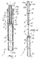
- the reference numeral 1 generally designates a cannula for dispensing fluid products P for vaginal and anal applications, particularly for the application of ointments, creams, medicinal pastes, or the like.
- the cannula 1 comprises a tubular body 2 for containing the product P, which is provided, at a first end 2a, with an outlet 3 for dispensing the product P and, at a second end 2b that lies opposite the first end, with a back wall 4 in which an opening 5 is formed.
- a plunger 6 is inserted in the tubular body 2 so that it can slide axially, and a pusher rod 7 is associated with said plunger and can be inserted slidingly in the opening 5.
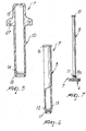
- the rod 7 is of the telescopic type; in the particular embodiment shown in the figures cited above, it comprises a stem 8, which has an end 8a that is formed monolithically with the plunger 6, an inner tubular body 9, which is fitted on the stem 8 substantially coaxially and so that it can slide axially, and an outer tubular portion 10, which is mounted substantially coaxially and so that it can slide axially on the inner tubular portion 9.
- the cannula 1 is sold full of product P in the closed packaging configuration, with the rod 7 in the retraction configuration, in which the stem 8 is retracted into the inner tubular portion 9, which is retracted into the outer tubular portion 10.
- the rod 7 assumes an elongation configuration, in which the stem 8 is extended outside the inner tubular portion 9, which is extended outside the outer tubular portion 10.
- the cannula 1 comprises means for temporarily retaining the stem 8, the inner tubular portion 9 and the outer tubular portion 10 in the retracted configuration of the rod 7, and means for locking the stem 8, the inner tubular portion 9 and the outer tubular portion 10 in the elongation configuration of the rod 7.
- the temporary retention means can be of the interlocking type and can be constituted for example by annular protrusions 11 and 12 formed so as to protrude respectively on the outer lateral surface of the stem 8 and of the inner tubular portion 9 and are coupled to complementary grooves 13 and 14 formed on the inner lateral surface of the inner tubular portion 9 and of the outer tubular portion 10 respectively.
- the locking means can be of the interlocking type and can be constituted for example by contoured heads 15 and 16, which are formed at the opposite ends, with respect to the plunger 6, of the stem 8 and of the inner tubular portion 9, respectively, and can be coupled to complementary seats 17 and 18 formed respectively in the inner tubular portion 9 and in the outer tubular portion 10.
- a grip is formed at the end of the outer tubular portion 10 that lies opposite with respect to the plunger 6 and is constituted for example by a knob 19 formed monolithically therewith.
- the cannula 1 further comprises means for capping the tubular body 2 and the rod 7 in the retraction configuration, which can be constituted for example by a covering sheath 20, which has a closed end 20a and an open opposite end 20b and which, when said cannula is in the closed packaging configuration, is fitted detachably over the tubular body 2 and on at least one portion of the rod 7 in the retraction configuration.
- a covering sheath 20 which has a closed end 20a and an open opposite end 20b and which, when said cannula is in the closed packaging configuration, is fitted detachably over the tubular body 2 and on at least one portion of the rod 7 in the retraction configuration.
- the dispensing outlet 3 is associated with detachable closure means, which can be constituted for example by a plug 21, which is formed inside the jacket 20 at its closed end 20a.
- the cannula 1 comprises detachable tamper-resistant means 22, which seal it in the closed packaging configuration.
- the tamper-resistant means 22 can comprise for example a tab 23, which can be removed by tearing, is wrapped around the outer tubular portion 10, and is associated, along respective tear lines 24 and 25 formed along its opposite longitudinal edges, with the sheath 20 and with a strip 26 that is rigidly coupled to the knob 19.
- the strip 26 comprises a fixing flap 26a, which is rigidly coupled to the knob 19, for example by interlocking in a seat 27 that is formed along the perimetric edge of said knob, and an indicator flap 26b, which protrudes from the seat 27 to indicate that the cannula 1 has been opened for the first time.
- the fixing flap 26a might be rigidly coupled to the knob 19 by way of systems other than interlocking, for example by gluing, welding, ultrasonic welding, or others.
- the cannula 1 is sold in the closed packaging configuration ( Figures 1 and 3 ), filled with product P; in this configuration, the rod 7 is locked temporarily in the retraction configuration by the annular protrusions 11 and 12 coupled to the corresponding grooves 13 and 14, while the sheath 20 caps the tubular body 2 and a portion of said rod and closes the dispensing outlet 3 with the plug 21.
- the sheath 20 is anchored temporarily to the knob 19 by way of tamper-resistant removable means 22.
- the sheath 20 is disengaged from the knob 19, while the strip 26 remains coupled to the knob 19, with the indicator flap 26b that protrudes from it so as to indicate that first opening has occurred.
- the interlocking of the heads 15 and 16 in the corresponding seats 17 and 18 locks the rod 7 in the elongation configuration; the rod 7 thus assumes a rigid configuration, which is capable of transmitting to the plunger 6 the thrust action that the user applies to it by means of the knob 19 in the direction for sliding toward the dispensing outlet 3 for the application of the product P.
- the cannula according to the invention is in fact compact, particularly with respect to known cannulas provided with a pusher rod formed by means of a single rigid body, and this compactness makes it easier to prepare, package and handle.
Landscapes
- Health & Medical Sciences (AREA)
- Engineering & Computer Science (AREA)
- Anesthesiology (AREA)
- Biomedical Technology (AREA)
- Heart & Thoracic Surgery (AREA)
- Hematology (AREA)
- Life Sciences & Earth Sciences (AREA)
- Animal Behavior & Ethology (AREA)
- General Health & Medical Sciences (AREA)
- Public Health (AREA)
- Veterinary Medicine (AREA)
- Infusion, Injection, And Reservoir Apparatuses (AREA)
- Measurement Of The Respiration, Hearing Ability, Form, And Blood Characteristics Of Living Organisms (AREA)
- External Artificial Organs (AREA)
Claims (19)
- Kanüle (1) zur Abgabe von flüssigen Produkten (P) für vaginale und anale Anwendungen mit:einem Röhrenkörper (2) zum Aufbewahren eines flüssigen Produktes, der - an einem ersten Ende (2a) - mit einem Auslass (3) zur Abgabe des Produktes bereitgestellt ist, und - an einem zweiten Ende (2b), welches dem ersten Ende (2a) gegenüber liegt - mit einer Rückwand (4) versehen ist, in der sich eine Öffnung (5) befindet,einem Plungerkolben (6), der so eingesetzt ist, dass er sich in den Röhrenkörper (2) axial verschieben kann, und miteinem Stößelstab (7, 8, 9, 10, 19), der mit dem Plungerkolben (6) in Verbindung steht und in die genannte Öffnung (5) verschiebbar eingesetzt wird,gekennzeichnet dadurch, dass der genannte Stößelstab (7, 8, 9, 10) teleskopisch ausziehbar und so ausgelegt ist, um eine eingezogene Betriebskonfiguration anzunehmen, wobei sich die Kanüle (1) in der geschlossenen Packanordnung befindet, und gekennzeichnet durch mindestens eine Verlängerungsanordnung, wobei sich die Kanüle (1) in der geöffneten Betriebskonfiguration für eine Anwendung befindet,und die Kanüle (1) dadurch gekennzeichnet ist, dass sie abnehmbare, manipulationssichere Mittel (22, 23, 24, 26) zum versiegeln der Kanüle (1) in der geschlossenen Packanordnung aufweist,worin die abnehmbaren, manipulationssicheren Mittel (22, 23) mit einem Griff (19) starr verbunden sind, der am Ende eines äußeren Röhrenabschnitts (10) des Stößelstab (7) ausgebildet ist, das zum Plungerkolben (6) gegenüberliegend angeordnet ist.
- Kanüle (1) gemäß Anspruch 1, dadurch gekennzeichnet, dass der Stößelstab (7) einen Schaft (8) aufweist, der mit einem Ende (8a) versehen ist, das mit dem Plungerkolben (6) monolithisch ausgebildet ist, und dadurch gekennzeichnet, dass der äußere Röhrenabschnitt (10) über dem Schaft (8) im Wesentlichen so koaxial eingepasst ist, dass er axial gleiten kann.
- Kanüle gemäß Anspruch 2, dadurch gekennzeichnet, dass der Stößelstab (7) mindestens einen röhrenförmigen Innenabschnitt (9) aufweist, der sich zwischen dem äußeren Röhrenabschnitt (10) und dem Schaft (8) befindet und mit diesem im Wesentlichen so koaxial verbunden ist, dass er axial gleiten kann.
- Kanüle gemäß den Ansprüchen 2 oder 3, dadurch gekennzeichnet, dass sie Mittel (11, 12, 13, 14) zum temporären Befestigen des Schaftes (8) und der Röhrenabschnitte (9, 10) des Stößelstabs (7) in der eingezogenen Betriebskonfiguration aufweist.
- Kanüle gemäß Anspruch 4, dadurch gekennzeichnet, dass die temporären Befestigungsmittel (11, 12, 13, 14) einen ineinandergreifenden Sperrmechanismus aufweisen.
- Kanüle gemäß Anspruch 5 in Abhängigkeit von Anspruch 2, dadurch gekennzeichnet, dass die temporären Befestigungsmittel mindestens einen vorsprung aufweisen, der so ausgebildet ist, dass er an der seitlichen Außenfläche des Schaftes (8) hervorsteht und mit einer komplementären Kerbe gekoppelt wird, die an der seitlichen Innenfläche des äußeren Röhrenabschnitts (10) ausgestaltet ist.
- Kanüle gemäß Anspruch 5 in Abhängigkeit von Anspruch 3, dadurch gekennzeichnet, dass die temporären Befestigungsmittel mindestens einen Vorsprung (11) aufweisen, der so ausgebildet ist, dass er an der seitlichen Außenfläche des Schaftes (8) hervorsteht und mit einer komplementären Kerbe (13) gekoppelt wird, die an der seitlichen Innenfläche des inneren Röhrenabschnitts (9) ausgestaltet ist, und mit mindestens einem Vorsprung (12) versehen ist, der so ausgestaltet ist, dass er an der seitlichen Außenfläche des inneren Röhrenabschnitts (9) hervorsteht und mit einer komplementären Kerbe (14) gekoppelt wird, die an der seitlichen Innenfläche des äußeren Röhrenabschnitts (10) ausgebildet ist.
- Kanüle gemäß den Ansprüchen 2 oder 3, dadurch gekennzeichnet, dass sie Mittel (15, 16, 17, 18) zum Fixieren des Schaftes (8) und der Röhrenabschnitte (9, 10) des Stößelstab (7) in der verlängerten Betriebskonfiguration aufweist.
- Kanüle gemäß Anspruch 8, dadurch gekennzeichnet, dass die Fixiermittel (15, 16, 17, 18) einen ineinandergreifenden Sperrmechanismus aufweisen.
- Kanüle gemäß Anspruch 9 in Abhängigkeit von Anspruch 2, dadurch gekennzeichnet, dass die Fixiermittel ein passend profiliertes Kopfteil aufweisen, das am Ende des Schaftes (8) ausgebildet ist, das zum Plungerkolben (6) gegenüberliegend angeordnet ist und das mit einem komplementären Einpasssitz gekoppelt werden kann, der in dem äußeren Röhrenabschnitt (10) ausgebildet ist.
- Kanüle gemäß Anspruch 9 in Abhängigkeit von Anspruch 3,
dadurch gekennzeichnet, dass die Fixiermittel ein passend profiliertes Kopfteil (15) aufweisen, das am Ende des Schaftes (8) ausgebildet ist, das zum Plungerkolben (6) gegenüberliegend angeordnet ist und mit einem komplementären Einpasssitz (17) gekoppelt werden kann, der in dem inneren Röhrenabschnitt (19) ausgestaltet ist, und ein konturierte Kopfteil (16), das am Ende des inneren Röhrenabschnitts (9) ausgebildet ist, das zum Plungerkolben (6) gegenüberliegend angeordnet ist und mit einem komplementären Einpasssitz (18) gekoppelt werden kann, der in dem äußeren Röhrenabschnitt (10) ausgebildet ist. - Kanüle gemäß den Ansprüchen 2 oder 3, dadurch gekennzeichnet, dass der Griff einen Knauf (19) aufweist, der am Ende des äußeren Röhrenabschnitts monolithisch ausgebildet ist, welcher zum Plungerkolben (6) gegenüberliegend angeordnet ist.
- Kanüle gemäß einem oder mehreren der vorhergehenden Ansprüche, dadurch gekennzeichnet, dass sie Mittel (20) zum Verkappen des Röhrenkörpers (2) und des Stößelstab (7) in der eingezogenen Betriebskonfiguration aufweist.
- Kanüle gemäß Anspruch 13, dadurch gekennzeichnet, dass die Verkappungsmittel eine Ummantelung (20) aufweisen, die ein geschlossenes Ende (20a) und ein entgegengesetzt offenes Ende (20b) umfasst, und die in der eingezogenen Betriebskonfiguration über dem Röhrenkörper (2) und über mindestens einem Abschnitt des Stößelstabs (7) entfernbar eingepasst ist.
- Kanüle gemäß Anspruch 14, dadurch gekennzeichnet, dass die abnehmbaren, manipulationssicheren Mittel (22) eine Lasche (23) aufweisen, die durch Abriss entfernt werden kann, die um den äußeren Röhrenabschnitt (10) gewunden ist und die längs der jeweiligen Reißlinien (24, 25), welche entlang den sich gegenüberliegenden Längsrändern des äußeren Röhrenabschnitts ausgebildet sind, mit der Ummantelung (20) und mit einem Bundring (26) verbunden ist, wobei dieser mit dem Griff (19) starr verbunden ist.
- Kanüle gemäß Anspruch 15, dadurch gekennzeichnet, dass der Bundring (26) eine Befestigungsklappe (26a) aufweist, die mit dem Perimeterrand des Griffes (19) starr verbunden ist, und eine Indikatorklappe (26b) umfasst, die von dem Rand hervorsteht.
- Kanüle (1) gemäß Anspruch 13, dadurch gekennzeichnet, dass sie abnehmbare Mittel (21) aufweist, die mit den Verkappungsmitteln (20) in Verbindung stehen, um die Spenderausgabe (3) zu verschließen.
- Kanüle gemäß Anspruch 17, dadurch gekennzeichnet, dass die abnehmbaren Verschlussmittel einen Abdichtstopfen (21) umfassen, welcher im Innern der Ummantelung (20) der Verkappungsmittel an deren geschlossenem Ende (20a) ausgestaltet ist.
- Kanüle gemäß einem oder mehreren der vorhergehenden Ansprüche, gekennzeichnet dadurch, dass der Stößelstab (7) einen Schaft (8) aufweist, der mit einem Ende (8a) versehen ist, das mit dem Plungerkolben (6) verbunden ist, dadurch gekennzeichnet, dass das Ende (8a) des Schaftes (8), das mit dem Plungerkolben (6) verbunden ist, mit diesem monolithisch ausgebildet ist.
Applications Claiming Priority (2)
| Application Number | Priority Date | Filing Date | Title |
|---|---|---|---|
| IT000264A ITMO20030264A1 (it) | 2003-09-26 | 2003-09-26 | Cannula per l'erogazione di prodotti fluidi |
| ITMO20030264 | 2003-09-26 |
Publications (3)
| Publication Number | Publication Date |
|---|---|
| EP1518574A2 EP1518574A2 (de) | 2005-03-30 |
| EP1518574A3 EP1518574A3 (de) | 2006-03-08 |
| EP1518574B1 true EP1518574B1 (de) | 2009-08-26 |
Family
ID=34179339
Family Applications (1)
| Application Number | Title | Priority Date | Filing Date |
|---|---|---|---|
| EP04021121A Expired - Lifetime EP1518574B1 (de) | 2003-09-26 | 2004-09-06 | Kanüle zur Abgabe von flüssigen Produkten zur analen und vaginalen Anwendung |
Country Status (4)
| Country | Link |
|---|---|
| EP (1) | EP1518574B1 (de) |
| AT (1) | ATE440634T1 (de) |
| DE (1) | DE602004022749D1 (de) |
| IT (1) | ITMO20030264A1 (de) |
Cited By (1)
| Publication number | Priority date | Publication date | Assignee | Title |
|---|---|---|---|---|
| US10640276B2 (en) | 2017-06-12 | 2020-05-05 | Bio-Techne Corporation | Dual chamber storage device |
Families Citing this family (8)
| Publication number | Priority date | Publication date | Assignee | Title |
|---|---|---|---|---|
| CN101175526B (zh) * | 2005-05-13 | 2011-02-02 | 科洛普拉斯特公司 | 伸缩式装置,其制备方法及其保持元件的使用方法 |
| WO2006119781A1 (en) * | 2005-05-13 | 2006-11-16 | Coloplast A/S | Retention element for telescopic device |
| WO2008117320A1 (en) * | 2007-03-28 | 2008-10-02 | Bormioli Rocco & Figlio S.P.A. | An applicator assembly for hygienic-medical irrigation, in particular for vaginal irrigation |
| US8172813B2 (en) * | 2008-02-28 | 2012-05-08 | Becton, Dickinson And Company | Syringe with two piece plunger rod |
| US7976510B2 (en) | 2008-02-28 | 2011-07-12 | Becton, Dickinson And Company | Syringe with adjustable two piece plunger rod |
| IT1393142B1 (it) | 2009-02-09 | 2012-04-11 | Lameplast Spa | Cannula per l'erogazione di prodotti fluidi, particolarmente per applicazioni vaginali e rettali |
| IT1393383B1 (it) | 2009-02-09 | 2012-04-20 | Lameplast Spa | Cannula per l'erogazione di prodotti fluidi, particolarmente per applicazioni vaginali e rettali |
| CN108888843B (zh) * | 2018-08-10 | 2023-06-27 | 中国人民解放军总医院 | 用于人体空腔伤口的粉末止血剂推进器 |
Family Cites Families (8)
| Publication number | Priority date | Publication date | Assignee | Title |
|---|---|---|---|---|
| US2630804A (en) * | 1948-02-24 | 1953-03-10 | Ortho Pharma Corp | Single dose cavity dispenser |
| FR2409761A1 (fr) * | 1977-11-29 | 1979-06-22 | Hache Claude | Seringue a course demultipliee |
| US4300678A (en) * | 1980-04-07 | 1981-11-17 | Becton, Dickinson And Company | Syringe package with evidence of opening |
| US4636202A (en) * | 1984-07-27 | 1987-01-13 | Syntex (U.S.A.) Inc. | Medicament applicator with plunger assembly and automatically-openable closure therefor |
| GB8702069D0 (en) * | 1987-01-30 | 1987-03-04 | High Trees Agriculture Ltd | Cleaning agricultural sprayers |
| ES2133090B1 (es) * | 1997-02-21 | 2000-04-01 | Uriach & Cia Sa J | Nuevo aplicador para la administracion de medicaciones semisolidas. |
| FR2821563B1 (fr) * | 2001-03-05 | 2004-05-14 | Becton Dickinson France | Seringue, ou dispositif similaire, a securite renforcee |
| DE60302335T2 (de) * | 2002-01-25 | 2006-08-10 | Novo Nordisk A/S | Linearantrieb und medizinische abgabevorrichtung mit einem solchen linearantrieb |
-
2003
- 2003-09-26 IT IT000264A patent/ITMO20030264A1/it unknown
-
2004
- 2004-09-06 AT AT04021121T patent/ATE440634T1/de not_active IP Right Cessation
- 2004-09-06 EP EP04021121A patent/EP1518574B1/de not_active Expired - Lifetime
- 2004-09-06 DE DE602004022749T patent/DE602004022749D1/de not_active Expired - Fee Related
Cited By (2)
| Publication number | Priority date | Publication date | Assignee | Title |
|---|---|---|---|---|
| US10640276B2 (en) | 2017-06-12 | 2020-05-05 | Bio-Techne Corporation | Dual chamber storage device |
| US10640275B2 (en) | 2017-06-12 | 2020-05-05 | Bio-Techne Corportion | Dual chamber storage device |
Also Published As
| Publication number | Publication date |
|---|---|
| ITMO20030264A1 (it) | 2005-03-27 |
| EP1518574A2 (de) | 2005-03-30 |
| ATE440634T1 (de) | 2009-09-15 |
| EP1518574A3 (de) | 2006-03-08 |
| DE602004022749D1 (de) | 2009-10-08 |
Similar Documents
| Publication | Publication Date | Title |
|---|---|---|
| US5560518A (en) | Fluid delivery system | |
| RU2173180C2 (ru) | Автоматическое изъятие поршневого штока | |
| US6364854B1 (en) | Applicator for semi-solid medications | |
| EP1518574B1 (de) | Kanüle zur Abgabe von flüssigen Produkten zur analen und vaginalen Anwendung | |
| US20050139613A1 (en) | Fluid dispenser assembly | |
| US7507223B2 (en) | Cannula for dispensing fluid products for vaginal and anal applications | |
| KR940013624A (ko) | 밀봉재료 분배기용 어댑터 | |
| US9833575B2 (en) | Syringe with plunger rod having a flexible portion | |
| US2477875A (en) | Dispensing container for collapsible tube with axially movable, rotatively actuated,follower-type extruder | |
| JP5658690B2 (ja) | 膣および直腸に特に適用される流動製品投薬用カニューレ | |
| EP2708154A1 (de) | Pflegeproduktverpackung | |
| US6343886B2 (en) | Semisolid substance container with movable bottom | |
| EP1732638B1 (de) | Kanüle zur abgabe von flüssigen produkten für vaginale und anale anwendungen | |
| ITMI991479A1 (it) | Cannula erogatrice di unguenti medicinali | |
| ITBO980012A1 (it) | Dispositivo dosatore ed erogatore di prodotti fluidi o pastosi di tipo manuale a siringa. | |
| US6474509B1 (en) | Toothpaste dispensing device | |
| EP2227272B1 (de) | Kanüle zur abgabe von flüssigen produkten, insbesondere für rektale anwendungen | |
| CN210353641U (zh) | 一种蝴蝶结直角拍盖软管 | |
| US2950027A (en) | Self-opening and self-closing dispenser | |
| KR20200001832U (ko) | 고형 물질의 투입이 용이한 주사기형 투입기 | |
| WO2002020364A1 (en) | Dispensing flowable material from a tubular dispenser | |
| EP1829515A1 (de) | Behälter und Auftrageinrichtung fuer pharmazeutische oder kosmetische Produkte | |
| HK1193326A (en) | Consumer care packaging | |
| ITMO970102A1 (it) | Applicatore monouso di pomate medicali per impiego ginecologico |
Legal Events
| Date | Code | Title | Description |
|---|---|---|---|
| PUAI | Public reference made under article 153(3) epc to a published international application that has entered the european phase |
Free format text: ORIGINAL CODE: 0009012 |
|
| AK | Designated contracting states |
Kind code of ref document: A2 Designated state(s): AT BE BG CH CY CZ DE DK EE ES FI FR GB GR HU IE IT LI LU MC NL PL PT RO SE SI SK TR |
|
| AX | Request for extension of the european patent |
Extension state: AL HR LT LV MK |
|
| RAP1 | Party data changed (applicant data changed or rights of an application transferred) |
Owner name: LAMEPLAST S.P.A. |
|
| PUAL | Search report despatched |
Free format text: ORIGINAL CODE: 0009013 |
|
| AK | Designated contracting states |
Kind code of ref document: A3 Designated state(s): AT BE BG CH CY CZ DE DK EE ES FI FR GB GR HU IE IT LI LU MC NL PL PT RO SE SI SK TR |
|
| AX | Request for extension of the european patent |
Extension state: AL HR LT LV MK |
|
| RIC1 | Information provided on ipc code assigned before grant |
Ipc: A61M 3/02 20060101ALI20060116BHEP Ipc: A61M 31/00 20060101AFI20060116BHEP |
|
| 17P | Request for examination filed |
Effective date: 20060807 |
|
| AKX | Designation fees paid |
Designated state(s): AT BE BG CH CY CZ DE DK EE ES FI FR GB GR HU IE IT LI LU MC NL PL PT RO SE SI SK TR |
|
| 17Q | First examination report despatched |
Effective date: 20070118 |
|
| GRAP | Despatch of communication of intention to grant a patent |
Free format text: ORIGINAL CODE: EPIDOSNIGR1 |
|
| GRAS | Grant fee paid |
Free format text: ORIGINAL CODE: EPIDOSNIGR3 |
|
| GRAA | (expected) grant |
Free format text: ORIGINAL CODE: 0009210 |
|
| AK | Designated contracting states |
Kind code of ref document: B1 Designated state(s): AT BE BG CH CY CZ DE DK EE ES FI FR GB GR HU IE IT LI LU MC NL PL PT RO SE SI SK TR |
|
| REG | Reference to a national code |
Ref country code: GB Ref legal event code: FG4D |
|
| REG | Reference to a national code |
Ref country code: CH Ref legal event code: EP |
|
| REG | Reference to a national code |
Ref country code: IE Ref legal event code: FG4D |
|
| REF | Corresponds to: |
Ref document number: 602004022749 Country of ref document: DE Date of ref document: 20091008 Kind code of ref document: P |
|
| PG25 | Lapsed in a contracting state [announced via postgrant information from national office to epo] |
Ref country code: SE Free format text: LAPSE BECAUSE OF FAILURE TO SUBMIT A TRANSLATION OF THE DESCRIPTION OR TO PAY THE FEE WITHIN THE PRESCRIBED TIME-LIMIT Effective date: 20090826 Ref country code: FI Free format text: LAPSE BECAUSE OF FAILURE TO SUBMIT A TRANSLATION OF THE DESCRIPTION OR TO PAY THE FEE WITHIN THE PRESCRIBED TIME-LIMIT Effective date: 20090826 Ref country code: AT Free format text: LAPSE BECAUSE OF FAILURE TO SUBMIT A TRANSLATION OF THE DESCRIPTION OR TO PAY THE FEE WITHIN THE PRESCRIBED TIME-LIMIT Effective date: 20090826 |
|
| NLV1 | Nl: lapsed or annulled due to failure to fulfill the requirements of art. 29p and 29m of the patents act | ||
| PG25 | Lapsed in a contracting state [announced via postgrant information from national office to epo] |
Ref country code: PL Free format text: LAPSE BECAUSE OF FAILURE TO SUBMIT A TRANSLATION OF THE DESCRIPTION OR TO PAY THE FEE WITHIN THE PRESCRIBED TIME-LIMIT Effective date: 20090826 Ref country code: NL Free format text: LAPSE BECAUSE OF FAILURE TO SUBMIT A TRANSLATION OF THE DESCRIPTION OR TO PAY THE FEE WITHIN THE PRESCRIBED TIME-LIMIT Effective date: 20090826 Ref country code: SI Free format text: LAPSE BECAUSE OF FAILURE TO SUBMIT A TRANSLATION OF THE DESCRIPTION OR TO PAY THE FEE WITHIN THE PRESCRIBED TIME-LIMIT Effective date: 20090826 |
|
| PG25 | Lapsed in a contracting state [announced via postgrant information from national office to epo] |
Ref country code: PT Free format text: LAPSE BECAUSE OF FAILURE TO SUBMIT A TRANSLATION OF THE DESCRIPTION OR TO PAY THE FEE WITHIN THE PRESCRIBED TIME-LIMIT Effective date: 20091228 Ref country code: CY Free format text: LAPSE BECAUSE OF FAILURE TO SUBMIT A TRANSLATION OF THE DESCRIPTION OR TO PAY THE FEE WITHIN THE PRESCRIBED TIME-LIMIT Effective date: 20090826 Ref country code: BG Free format text: LAPSE BECAUSE OF FAILURE TO SUBMIT A TRANSLATION OF THE DESCRIPTION OR TO PAY THE FEE WITHIN THE PRESCRIBED TIME-LIMIT Effective date: 20091126 |
|
| PG25 | Lapsed in a contracting state [announced via postgrant information from national office to epo] |
Ref country code: CZ Free format text: LAPSE BECAUSE OF FAILURE TO SUBMIT A TRANSLATION OF THE DESCRIPTION OR TO PAY THE FEE WITHIN THE PRESCRIBED TIME-LIMIT Effective date: 20090826 Ref country code: RO Free format text: LAPSE BECAUSE OF FAILURE TO SUBMIT A TRANSLATION OF THE DESCRIPTION OR TO PAY THE FEE WITHIN THE PRESCRIBED TIME-LIMIT Effective date: 20090826 Ref country code: EE Free format text: LAPSE BECAUSE OF FAILURE TO SUBMIT A TRANSLATION OF THE DESCRIPTION OR TO PAY THE FEE WITHIN THE PRESCRIBED TIME-LIMIT Effective date: 20090826 Ref country code: DK Free format text: LAPSE BECAUSE OF FAILURE TO SUBMIT A TRANSLATION OF THE DESCRIPTION OR TO PAY THE FEE WITHIN THE PRESCRIBED TIME-LIMIT Effective date: 20090826 Ref country code: ES Free format text: LAPSE BECAUSE OF FAILURE TO SUBMIT A TRANSLATION OF THE DESCRIPTION OR TO PAY THE FEE WITHIN THE PRESCRIBED TIME-LIMIT Effective date: 20091207 Ref country code: MC Free format text: LAPSE BECAUSE OF NON-PAYMENT OF DUE FEES Effective date: 20090930 |
|
| REG | Reference to a national code |
Ref country code: CH Ref legal event code: PL |
|
| PG25 | Lapsed in a contracting state [announced via postgrant information from national office to epo] |
Ref country code: SK Free format text: LAPSE BECAUSE OF FAILURE TO SUBMIT A TRANSLATION OF THE DESCRIPTION OR TO PAY THE FEE WITHIN THE PRESCRIBED TIME-LIMIT Effective date: 20090826 |
|
| PG25 | Lapsed in a contracting state [announced via postgrant information from national office to epo] |
Ref country code: BE Free format text: LAPSE BECAUSE OF FAILURE TO SUBMIT A TRANSLATION OF THE DESCRIPTION OR TO PAY THE FEE WITHIN THE PRESCRIBED TIME-LIMIT Effective date: 20090826 |
|
| PLBE | No opposition filed within time limit |
Free format text: ORIGINAL CODE: 0009261 |
|
| STAA | Information on the status of an ep patent application or granted ep patent |
Free format text: STATUS: NO OPPOSITION FILED WITHIN TIME LIMIT |
|
| GBPC | Gb: european patent ceased through non-payment of renewal fee |
Effective date: 20091126 |
|
| PG25 | Lapsed in a contracting state [announced via postgrant information from national office to epo] |
Ref country code: IE Free format text: LAPSE BECAUSE OF NON-PAYMENT OF DUE FEES Effective date: 20090906 Ref country code: DE Free format text: LAPSE BECAUSE OF NON-PAYMENT OF DUE FEES Effective date: 20100401 |
|
| 26N | No opposition filed |
Effective date: 20100527 |
|
| PG25 | Lapsed in a contracting state [announced via postgrant information from national office to epo] |
Ref country code: CH Free format text: LAPSE BECAUSE OF NON-PAYMENT OF DUE FEES Effective date: 20090930 Ref country code: GR Free format text: LAPSE BECAUSE OF FAILURE TO SUBMIT A TRANSLATION OF THE DESCRIPTION OR TO PAY THE FEE WITHIN THE PRESCRIBED TIME-LIMIT Effective date: 20091127 Ref country code: LI Free format text: LAPSE BECAUSE OF NON-PAYMENT OF DUE FEES Effective date: 20090930 |
|
| PG25 | Lapsed in a contracting state [announced via postgrant information from national office to epo] |
Ref country code: GB Free format text: LAPSE BECAUSE OF NON-PAYMENT OF DUE FEES Effective date: 20091126 |
|
| PGFP | Annual fee paid to national office [announced via postgrant information from national office to epo] |
Ref country code: IT Payment date: 20100930 Year of fee payment: 7 |
|
| PG25 | Lapsed in a contracting state [announced via postgrant information from national office to epo] |
Ref country code: LU Free format text: LAPSE BECAUSE OF NON-PAYMENT OF DUE FEES Effective date: 20090906 |
|
| REG | Reference to a national code |
Ref country code: FR Ref legal event code: ST Effective date: 20110502 |
|
| PG25 | Lapsed in a contracting state [announced via postgrant information from national office to epo] |
Ref country code: HU Free format text: LAPSE BECAUSE OF FAILURE TO SUBMIT A TRANSLATION OF THE DESCRIPTION OR TO PAY THE FEE WITHIN THE PRESCRIBED TIME-LIMIT Effective date: 20100227 |
|
| PG25 | Lapsed in a contracting state [announced via postgrant information from national office to epo] |
Ref country code: FR Free format text: LAPSE BECAUSE OF NON-PAYMENT OF DUE FEES Effective date: 20091026 |
|
| PG25 | Lapsed in a contracting state [announced via postgrant information from national office to epo] |
Ref country code: TR Free format text: LAPSE BECAUSE OF FAILURE TO SUBMIT A TRANSLATION OF THE DESCRIPTION OR TO PAY THE FEE WITHIN THE PRESCRIBED TIME-LIMIT Effective date: 20090826 |
|
| PG25 | Lapsed in a contracting state [announced via postgrant information from national office to epo] |
Ref country code: IT Free format text: LAPSE BECAUSE OF NON-PAYMENT OF DUE FEES Effective date: 20110906 |