EP1518479B1 - Bewegbarer Träger für Bürozubehör - Google Patents
Bewegbarer Träger für Bürozubehör Download PDFInfo
- Publication number
- EP1518479B1 EP1518479B1 EP03360126A EP03360126A EP1518479B1 EP 1518479 B1 EP1518479 B1 EP 1518479B1 EP 03360126 A EP03360126 A EP 03360126A EP 03360126 A EP03360126 A EP 03360126A EP 1518479 B1 EP1518479 B1 EP 1518479B1
- Authority
- EP
- European Patent Office
- Prior art keywords
- removable support
- work surface
- support according
- support
- threaded
- Prior art date
- Legal status (The legal status is an assumption and is not a legal conclusion. Google has not performed a legal analysis and makes no representation as to the accuracy of the status listed.)
- Expired - Lifetime
Links
- 230000002093 peripheral effect Effects 0.000 claims description 6
- 238000006073 displacement reaction Methods 0.000 claims description 4
- 229920006362 Teflon® Polymers 0.000 claims description 3
- 230000000295 complement effect Effects 0.000 claims description 3
- 238000000926 separation method Methods 0.000 claims description 3
- 238000010079 rubber tapping Methods 0.000 description 4
- 239000004809 Teflon Substances 0.000 description 1
- 230000037431 insertion Effects 0.000 description 1
- 238000003780 insertion Methods 0.000 description 1
- 230000000284 resting effect Effects 0.000 description 1
- 230000002747 voluntary effect Effects 0.000 description 1
Images


Classifications
-
- A—HUMAN NECESSITIES
- A47—FURNITURE; DOMESTIC ARTICLES OR APPLIANCES; COFFEE MILLS; SPICE MILLS; SUCTION CLEANERS IN GENERAL
- A47B—TABLES; DESKS; OFFICE FURNITURE; CABINETS; DRAWERS; GENERAL DETAILS OF FURNITURE
- A47B19/00—Reading-desks; Lecterns; Pulpits, i.e. free-standing
- A47B19/10—Reading-desks; Lecterns; Pulpits, i.e. free-standing characterised by association with auxiliary devices, e.g. paper clamps, line indicators
-
- A—HUMAN NECESSITIES
- A47—FURNITURE; DOMESTIC ARTICLES OR APPLIANCES; COFFEE MILLS; SPICE MILLS; SUCTION CLEANERS IN GENERAL
- A47B—TABLES; DESKS; OFFICE FURNITURE; CABINETS; DRAWERS; GENERAL DETAILS OF FURNITURE
- A47B13/00—Details of tables or desks
- A47B13/08—Table tops; Rims therefor
- A47B13/16—Holders for glasses, ashtrays, lamps, candles or the like forming part of tables
-
- A—HUMAN NECESSITIES
- A47—FURNITURE; DOMESTIC ARTICLES OR APPLIANCES; COFFEE MILLS; SPICE MILLS; SUCTION CLEANERS IN GENERAL
- A47B—TABLES; DESKS; OFFICE FURNITURE; CABINETS; DRAWERS; GENERAL DETAILS OF FURNITURE
- A47B21/00—Tables or desks for office equipment, e.g. typewriters, keyboards
- A47B21/04—Tables or desks for office equipment, e.g. typewriters, keyboards characterised by means for holding or fastening typewriters or computer equipment
- A47B21/045—Fastening means for paper sheet; Paper trays; Accessories for typists, e.g. line indicators
-
- B—PERFORMING OPERATIONS; TRANSPORTING
- B25—HAND TOOLS; PORTABLE POWER-DRIVEN TOOLS; MANIPULATORS
- B25B—TOOLS OR BENCH DEVICES NOT OTHERWISE PROVIDED FOR, FOR FASTENING, CONNECTING, DISENGAGING OR HOLDING
- B25B5/00—Clamps
Definitions
- the present invention relates to the general technical field of office furniture and office accessories or worktops.
- the invention relates to a removable support for accessories to be mounted on a worktop.
- This removable support comprises mounting means on an edge of the work plane and locking / unlocking means for moving and stably positioning said support on the edge of the work plane.
- a lighting means or a computer screen can be mounted on the removable support.
- Other accessories can also be mounted on the removable support.
- the known removable supports are generally fixed on the edge of the worktop via a vise system actuated by screws. These removable media often have locking / unlocking means that are difficult to access and require lengthy handling before moving said removable support.
- the known removable media are generally unsuitable for supporting large loads such as computer or television screens while maintaining the ability to be moved easily and stably by the user. Optimal positioning of the achievable accessory easily and quickly can not generally be achieved with known removable media.
- US Patent 5938150 discloses a removable medium to be mounted on the edge of a worktop.
- the object of the present invention is thus to provide a removable support whose locking / unblocking on the edge of a worktop and its movement with or without an accessory is easy and fast.
- the locking / unlocking means comprise a single gripping member intended to extend above the working plane and whose manipulation makes it possible to block / unblock and move said support along the edge.
- the threaded upper portion comprises three branches in the extension of the link arm and arranged relative to each other in a specific angular orientation, one of the branches being intended to overhang the work plane.
- the threaded upper portion has a substantially V-shaped, in a cross section, each vertex is provided with a longitudinal thread.
- the thread portions extend over a length less than that of the longitudinal windows, to allow sliding in the cylinder.
- the end of the cylinder from which the tube extends comprises on a peripheral zone a stop lug cooperating with a bearing lug provided on the tapping of the gripping member, said support pin resting and moving on a given stroke of the peripheral zone, delimited by the stop lug.
- a safety device prevents the separation of the lower and upper jaws of the work plane.
- the device comprises a rod secured to the lower jaw, and having a bent end, engaged behind a stop of the work plane.
- the stop is a groove formed in the underside of the work plane.
- the stop is a substantially L-shaped part, fixed under the work plan.
- the device comprises teflon pads attached to the upper jaw and providing the interface with the work plane.
- the object of the present invention is also achieved with office furniture equipped with a removable support as presented above.
- the removable support according to the invention is for example intended to support accessories of a worktop 1.
- the removable support comprises mounting means on an edge of the worktop 1. These mounting means make it possible to obtain a Stable and rigid positioning to support accessories such as computer screen, television or others.
- the removable support comprises locking / unlocking means for stably moving and positioning said support on the edge of the worktop 1.
- the locking / unlocking means comprise a gripping member 2 intended to extend above the working plane 1.
- the gripping member 2 is thus easily accessible to the user in a sitting or standing position with respect to the plane
- the user is required to actuate only the gripping member 2 to block and unblock the removable medium, and to move and position the latter optimally on the work plane 1 and more specifically the along the edge of said work plane 1.
- the removable support comprises a lower jaw 3 extending at least partially under the work plane 1.
- the lower jaw 3 thanks to a support plate 3a, allows the removable support to bear on the underside of the plane of work 1.
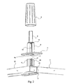
- the removable support further comprises an upper jaw 4 bearing on the work plane 1 with another support plate 4a. 1 and 2.
- the upper jaw 4 allows the removable support to bear on the upper face of the work plane 1 and supports the weight of the molded accessory on the work plane 1.
- the removable support also comprises an actuating mechanism associated with the gripping member 2, ensuring the relative clamping and loosening of the lower jaw 3 and upper jaw 4.
- the actuating mechanism thus makes it possible to grip the work plane 1 between the lower jaw 3 and upper 4 with manipulation of the gripping member 2, controlling the relative movements of said jaws 3 and 4.
- the actuating mechanism comprises a connecting arm 5 secured to the lower jaw 3 and extending substantially orthogonally to the support plate 3a.
- the link arm 5 also has a threaded upper portion 6.
- the threaded upper portion 6 extends above the worktop 1, thus making it easily accessible.
- the actuating mechanism also comprises an opening 7 of complementary shape to the upper threaded portion 6 and formed in the other support plate 4a.
- the opening 7 can thus be traversed by the threaded upper part 6 protruding above the working plane 1.
- the opening 7 opens onto a hollow cylinder 8, itself extended by a tube 9 of reduced diameter relative to the hollow cylinder 8.
- the latter is secured to the upper jaw 4 and the tube 9. It is on the tube 9 that the accessories are engaged.
- the actuating mechanism also comprises longitudinal windows 10, formed in the hollow cylinder 8 starting from the opening 7.
- the threaded upper part 6 thus engages and moves in the hollow cylinder 8 with threading portions 6a making protruding out of the longitudinal windows 10.
- the gripping member 2 is advantageously a sleeve engaged on the hollow cylinder 8 and having a tapping 11, shown for example in Figure 7.
- the tapping 11 engages with the thread portions 6a.
- the threaded upper portion 6 comprises three branches 12a, 12b, 12c in the extension of the connecting arm 5. These three branches 12a, 12b, 12c are arranged relative to each other in a same identical angular orientation the angular orientation of the longitudinal windows 10 formed in the hollow cylinder 8. The one 12c of the branches is shaped to overhang the work plane 1. Reference can be made for example to Figure 5.
- the threaded upper portion 6 has for example a substantially V shape in a cross section, each vertex is provided with a longitudinal thread portion 6a.
- the thread portions 6a extend longitudinally over a length less than that of the longitudinal windows 10 thus allowing sliding in the hollow cylinder 8.
- the longitudinal dimensions of the connecting arm 5 are chosen to allow movement of the lower jaw 3 by relative to the work plane 1 whose edge extends between the support plates 3a and 4a.
- the end of the hollow cylinder 8 from which the tube 9 extends comprises on a peripheral zone 13 a stop lug 14.
- the latter cooperates with a bearing lug 15 provided on the tapping 11 of the body of the 2.
- the support pin 15 rests and moves on the peripheral zone 13 along the race defined by the stop lug 14.
- the the support pin 15 and the stop lug 14 are provided to limit the rotation of the gripping member 2 during the release of the removable support. This release corresponds to a loosening of the lower jaw 3 and upper 4 and more precisely to a downward movement of the lower jaw 3.
- the removable support comprises a safety device preventing the separation of the lower jaw 3 and upper 4 of the work plane 1 during the displacement of said support. This gives a safety of use, in this case when an accessory is mounted on the removable support, when the gripping member 2 is in an unlocking position for moving said support along the work plane 1. A rearward movement, that is to say a clearance of the work plan 1 is thus impossible without additional voluntary action.
- the safety device comprises for example a rod 16 secured to the lower jaw 3 and having a bent end 17 cooperating with a stop of the work plane 1.
- the stop is for example a groove 18 formed in the underside of the work plan 1.
- the stop is a piece 19 substantially L-shaped, fixed under the work plane 1.
- the rod 16 is secured to a section 20 of rectangular section fixed for example by means of screws 21 on the support plate 3a.
- This profile 20 advantageously has the same dimensions in thickness as the plane of Work 1 and also provides additional support for the tray 4a.
- the lower jaw 3 and upper 4 therefore rest on a rigid support on either side of the link arm 5, contributing to the mounting stability of the removable support.
- the profile 20 is simply clamped between the lower and upper jaws 3 and is not associated with any other fastening means on said lower jaw 3.
- the safety devices are replaced by a fixed profile 22 integral with the worktop 1.
- This fixed profile 22 is fixed by any means on the worktop 1 and present by relative to the latter, a given spacing making it possible to provide an insertion slot 23 for the lower jaw 3.
- the removable support comprises Teflon® pads 24 fixed on the upper jaw 4 and forming the interface with the worktop 1. It is thus possible to slide with a large diameter. facilitates the removable support on the worktop 1.
- the accessory intended to be mounted on the removable support, according to the invention is preferably provided with a mounting member, not shown, engaging in or on the tube 9.
- the engagement member is a not shown hollow tube whose end rests on the upper end 8a of the hollow cylinder 8.
- the pitch of the thread portions 6a is chosen to generate with a rotation for example of a quarter turn of the gripping member 2, a sufficient movement of the lower jaw 3, allowing the sliding of the removable support on the work plane 1.
- the displacement of the lower jaw 3, corresponding to the release is defined by the arrival at the stop of the bearing lug 15 on the stop lug 14.
- the pitch of the thread portions 6a is adapted to the thickness, in general standard work plans 1.
- the dimensions of the angled end 17, the groove 18 or the part 19 are also chosen to avoid relative disengagement following release, that is to say the downward movement of the lower jaw 3, corresponding to the rotation of the gripping member 2 arriving in abutment. Any disengagement between the removable support and the work plane 1 is thus prevented during its sliding on said work plane 1.
- the user can move any accessory on a worktop with great security, in the absence of a fixed profile 22.
- Another advantage of the removable support according to the invention resides in the fact that any manipulation relating thereto is reduced to the rotation of the gripping member 2 over a fraction of a turn.
- Another advantage of the removable support according to the invention lies in the positioning of the clamping axis of the lower jaw 3 and upper 4. This axis is offset to the interior of the work plane 1 and thanks to the conformation of the branches 12a, 12b, 12c, and in particular thanks to the overhanging position of the branch 12c relative to the working plane 1. This provides a more efficient clamping and a more stable positioning of the removable support on the work plane 1.
- Another advantage related to the removable support according to the invention lies in the concentric mounting of the hollow cylinder 8 of the tube 9 and the gripping member 2.
Landscapes
- Engineering & Computer Science (AREA)
- Computer Hardware Design (AREA)
- General Engineering & Computer Science (AREA)
- Mechanical Engineering (AREA)
- Mutual Connection Of Rods And Tubes (AREA)
- Tables And Desks Characterized By Structural Shape (AREA)
- Clamps And Clips (AREA)
- Manipulator (AREA)
- Casings For Electric Apparatus (AREA)
- Telephone Function (AREA)
- Furniture Connections (AREA)
Claims (11)
- Bewegbarer Träger für Zubehör für eine Arbeitsfläche (1), umfassend:- eine untere Backe (3), die sich zumindest teilweise unter der Arbeitsfläche (1) erstreckt,- eine obere Backe (4), die auf die Arbeitsfläche (1) aufliegen kommt,- einen Betätigungsmechanismus, der mit dem Greiforgan (2) verknüpft ist, wobei das Festziehen und das Lockern jeweils der unteren (3) und der oberen (4) Backe gewährleistet wird,- Sperr-/Freigabemittel, die das stabile Verschieben und Positionieren des Trägers auf der Kante der Arbeitsfläche (1) ermöglichen, wobei die Sperr-/Freigabemittel ein einziges Greiforgan (2) umfassen, das dazu vorgesehen ist, sich über der Arbeitsfläche (1) auszustrecken, und dessen Handhabung das Sperren/Freigeben des Trägers entlang der Kante ermöglicht, dadurch gekennzeichnet, dass er eine Sicherheitsvorrichtung umfasst, die das Trennen der unteren (3) und der oberen (4) Backe der Arbeitsfläche (1) während des Verschiebens des Trägers verhindert, wobei die Verschiebung und die Positionierung des Trägers lediglich durch die Handhabung des Greiforgans (2) erfolgen.
- Bewegbarer Träger nach Anspruch 1, dadurch gekennzeichnet, dass der Betätigungsmechanismus umfasst:- einen Verbindungsarm (5), der sich im Wesentlichen orthogonal zur unteren Backe (3) erstreckt und einen oberen Gewindeteil (5) aufweist,- eine Öffnung (7), die eine zum oberen Gewindeteil (5) komplementäre Form aufweist und in der oberen Backe (4) angeordnet ist, wobei die Öffnung (7) in einen hohlen Zylinder (8) einmündet, der selbst um ein Rohr (9) mit einem hinsichtlich des hohlen Zylinders (8) reduzierten Durchmesser verlängert ist, der mit der oberen Backe (4) des Rohrs (9) verbunden ist,- longitudinale Fenster (10), die in dem Zylinder (8) aus der Öffnung (7) angeordnet sind,- wobei der obere Gewindeteil (6) mittels Gewindeabschnitten (6a), die über die longitudinalen Fenster (10) hinausragen, in den Zylinder (8) eingreift und sich in diesem verschiebt.- wobei das Greiforgan (2) eine Muffe ist, die mit dem Zylinder (8) in Eingriff ist und einen Gewindegang (11) aufweist, das in die Gewindeabschnitte (6a) greift.
- Bewegbarer Träger nach Anspruch 2, dadurch gekennzeichnet, dass der obere Gewindeteil in der Verlängerung des Verbindungsarms drei Zweige umfasst und diese hinsichtlich einander nach einer bestimmten winkligen Ausrichtung angeordnet sind, wobei ein Zweig angepasst ist, um die Arbeitsfläche zu überhängen.
- Bewegbarer Träger nach Anspruch 3, dadurch gekennzeichnet, dass der obere Gewindeteil im Querschnitt eine im Wesentlichen V-förmige Form aufweist, wobei jeder Gipfel davon mit einem longitudinalen Gewindeabschnitt (6a) versehen ist.
- Bewegbarer Träger nach einem der Ansprüche 2 bis 4, dadurch gekennzeichnet, dass die Gewindeabschnitte (6a) sich der Länge nach auf einer unteren Länge zu derjenigen der longitudinalen Fenster (10) erstrecken, um ein Gleiten im Zylinder zu ermöglichen.
- Bewegbarer Träger nach einem der Ansprüche 2 bis 5, dadurch gekennzeichnet, dass ein Ende (8a) des Zylinders (8), von dem aus sich das Rohr (9) erstreckt, auf einer peripheren Zone (13) eine Haltenoppe (14) umfasst, die mit einer Stütznoppe (15), die auf dem Gewindegang (11) des Greiforgans (2) bereitgestellt ist, zusammenarbeitet, wobei die Stütznoppe (15) auf der peripheren Zone (13) aufliegt und sich auf dieser nach einem Weg, der durch die Haltenoppe (14) begrenzt ist, verschiebt.
- Bewegbarer Träger nach einem der Ansprüche 1 bis 6, dadurch gekennzeichnet, dass die Sicherheitsvorrichtung einen Zweig (16), der mit der unteren Backe (3) verbunden ist und ein gebogenes Ende (17) aufweist, das mit einem Anschlag der Arbeitsfläche (1) zusammenarbeitet, umfasst.
- Bewegbarer Träger nach Anspruch 7, dadurch gekennzeichnet, dass der Anschlag eine Nut (18) ist, die auf der unteren Seite der Arbeitsfläche (1) angeordnet ist.
- Bewegbarer Träger nach Anspruch 7, dadurch gekennzeichnet, dass der Anschlag ein im Wesentlichen L-förmiges Stück (19) ist, das auf der Arbeitsfläche (1) befestigt ist.
- Bewegbarer Träger nach einem der Ansprüche 1 bis 9, dadurch gekennzeichnet, dass er Gleitschuhe (24) aus Teflon®, welche an der oberen Backe (4) angebaut sind und eine Schnittstelle mit der Arbeitsfläche (1) verwirklichen, umfasst.
- Büromöbel, das mit einem bewegbaren Träger gemäß einem der Ansprüche 1 bis 10 ausgestattet ist.
Applications Claiming Priority (2)
| Application Number | Priority Date | Filing Date | Title |
|---|---|---|---|
| FR0311213 | 2003-09-24 | ||
| FR0311213 | 2003-09-24 |
Publications (2)
| Publication Number | Publication Date |
|---|---|
| EP1518479A1 EP1518479A1 (de) | 2005-03-30 |
| EP1518479B1 true EP1518479B1 (de) | 2007-09-19 |
Family
ID=34178951
Family Applications (1)
| Application Number | Title | Priority Date | Filing Date |
|---|---|---|---|
| EP03360126A Expired - Lifetime EP1518479B1 (de) | 2003-09-24 | 2003-11-04 | Bewegbarer Träger für Bürozubehör |
Country Status (5)
| Country | Link |
|---|---|
| EP (1) | EP1518479B1 (de) |
| AT (1) | ATE373431T1 (de) |
| DE (1) | DE60316441T2 (de) |
| ES (1) | ES2294257T3 (de) |
| WO (1) | WO2005034679A1 (de) |
Families Citing this family (1)
| Publication number | Priority date | Publication date | Assignee | Title |
|---|---|---|---|---|
| FR2931346B1 (fr) * | 2008-05-23 | 2010-08-13 | Unik | Meuble de bureau convivial |
Family Cites Families (2)
| Publication number | Priority date | Publication date | Assignee | Title |
|---|---|---|---|---|
| GB201717A (en) * | 1922-06-26 | 1923-08-09 | Ernest Oliver Reynolds | Improvements in or relating to apparatus for retouching photographs and the like |
| US5938158A (en) * | 1996-03-22 | 1999-08-17 | Custom Plastics, Inc. | Desktop support structure |
-
2003
- 2003-11-04 AT AT03360126T patent/ATE373431T1/de not_active IP Right Cessation
- 2003-11-04 ES ES03360126T patent/ES2294257T3/es not_active Expired - Lifetime
- 2003-11-04 DE DE60316441T patent/DE60316441T2/de not_active Expired - Lifetime
- 2003-11-04 EP EP03360126A patent/EP1518479B1/de not_active Expired - Lifetime
-
2004
- 2004-05-28 WO PCT/FR2004/001338 patent/WO2005034679A1/fr active Application Filing
Also Published As
| Publication number | Publication date |
|---|---|
| WO2005034679A1 (fr) | 2005-04-21 |
| ATE373431T1 (de) | 2007-10-15 |
| EP1518479A1 (de) | 2005-03-30 |
| DE60316441D1 (de) | 2007-10-31 |
| ES2294257T3 (es) | 2008-04-01 |
| DE60316441T2 (de) | 2008-04-24 |
Similar Documents
| Publication | Publication Date | Title |
|---|---|---|
| FR2903927A1 (fr) | Dispositif d'assemblage rapide d'outillage sur support. | |
| FR2895301A1 (fr) | Machine a couper les carreaux. | |
| CA2102073A1 (fr) | Dispositif d'accouplement reglable de l'entrainement de la tige d'axe agitateur des dispositifs agitateurs, sur les machines d'agitation de peinture | |
| EP2795010B1 (de) | Vorrichtung zur befestigung einer blende an einer büroarbeitsplatte | |
| EP3256371A1 (de) | Zusammenklappbare wandmontierte stütze | |
| EP1518479B1 (de) | Bewegbarer Träger für Bürozubehör | |
| EP0418145B1 (de) | Andruckelement zum Aufspannen von Werkstücken | |
| EP2927517B1 (de) | Fahrrad mit einer schnelllösenden Sattelverstelleinrichtung und schnelllösende Sattelverstelleinrichtung ein solches Fahrrad | |
| FR3094280A1 (fr) | Mécanisme de serrage de boule d’attelage et porte-bicyclettes le comprenant | |
| FR2754596A1 (fr) | Guidon reglable pour un fusil d'assaut de la serie m16 a1-a2 -a3 | |
| FR3008896A1 (fr) | Systeme de fixation reglable pour planche de glisse et planche equipee d’un tel systeme | |
| FR3004480A1 (fr) | Structure pliable de travail en encorbellement integrant un dispositif d'aide au depliage d'un auvent | |
| FR3058307B1 (fr) | Dispositif de traitement d'aliments cooperant avec plusieurs recipients de cuisson | |
| FR2796582A3 (fr) | Dispositif pour aiguiser des forets de perceuses fixes et portatives | |
| FR3058306B1 (fr) | Dispositif de traitement d'aliments muni d'un systeme de fixation d'un outil | |
| FR2678538A1 (fr) | Outil de vissage. | |
| FR2767730A1 (fr) | Dispositif de bridage vertical a force d'application elevee | |
| FR2565454A1 (fr) | Faucheuse rotative | |
| FR3066686B1 (fr) | Dispositif d’appui assis-debout et poste de travail manuel equipe de celui-ci | |
| FR2987391A1 (fr) | Charniere pivot | |
| FR3134835A1 (fr) | Dispositif de fixation d’une poignée | |
| FR2819440A1 (fr) | Dispositif de guidage d'un organe de vissage du type tournevis | |
| EP4425277A1 (de) | Unterarmstütze für eine taktbank und taktbank | |
| WO2024003293A1 (fr) | Ensemble de tige de selle | |
| FR2744409A1 (fr) | Dispositif antivol pour vehicules, permettant de bloquer au moins une pedale |
Legal Events
| Date | Code | Title | Description |
|---|---|---|---|
| PUAI | Public reference made under article 153(3) epc to a published international application that has entered the european phase |
Free format text: ORIGINAL CODE: 0009012 |
|
| AK | Designated contracting states |
Kind code of ref document: A1 Designated state(s): AT BE BG CH CY CZ DE DK EE ES FI FR GB GR HU IE IT LI LU MC NL PT RO SE SI SK TR |
|
| AX | Request for extension of the european patent |
Extension state: AL LT LV MK |
|
| 17P | Request for examination filed |
Effective date: 20050401 |
|
| AKX | Designation fees paid |
Designated state(s): AT BE BG CH CY CZ DE DK EE ES FI FR GB GR HU IE IT LI LU MC NL PT RO SE SI SK TR |
|
| GRAP | Despatch of communication of intention to grant a patent |
Free format text: ORIGINAL CODE: EPIDOSNIGR1 |
|
| GRAS | Grant fee paid |
Free format text: ORIGINAL CODE: EPIDOSNIGR3 |
|
| GRAA | (expected) grant |
Free format text: ORIGINAL CODE: 0009210 |
|
| AK | Designated contracting states |
Kind code of ref document: B1 Designated state(s): AT BE BG CH CY CZ DE DK EE ES FI FR GB GR HU IE IT LI LU MC NL PT RO SE SI SK TR |
|
| REG | Reference to a national code |
Ref country code: GB Ref legal event code: FG4D Free format text: NOT ENGLISH |
|
| REG | Reference to a national code |
Ref country code: CH Ref legal event code: EP |
|
| REF | Corresponds to: |
Ref document number: 60316441 Country of ref document: DE Date of ref document: 20071031 Kind code of ref document: P |
|
| REG | Reference to a national code |
Ref country code: IE Ref legal event code: FG4D Free format text: LANGUAGE OF EP DOCUMENT: FRENCH |
|
| GBT | Gb: translation of ep patent filed (gb section 77(6)(a)/1977) |
Effective date: 20071212 |
|
| RAP2 | Party data changed (patent owner data changed or rights of a patent transferred) |
Owner name: STEELCASE SA |
|
| PG25 | Lapsed in a contracting state [announced via postgrant information from national office to epo] |
Ref country code: FI Free format text: LAPSE BECAUSE OF FAILURE TO SUBMIT A TRANSLATION OF THE DESCRIPTION OR TO PAY THE FEE WITHIN THE PRESCRIBED TIME-LIMIT Effective date: 20070919 |
|
| NLT2 | Nl: modifications (of names), taken from the european patent patent bulletin |
Owner name: STEELCASE SA Effective date: 20080109 |
|
| REG | Reference to a national code |
Ref country code: ES Ref legal event code: FG2A Ref document number: 2294257 Country of ref document: ES Kind code of ref document: T3 |
|
| PG25 | Lapsed in a contracting state [announced via postgrant information from national office to epo] |
Ref country code: GR Free format text: LAPSE BECAUSE OF FAILURE TO SUBMIT A TRANSLATION OF THE DESCRIPTION OR TO PAY THE FEE WITHIN THE PRESCRIBED TIME-LIMIT Effective date: 20071220 |
|
| PG25 | Lapsed in a contracting state [announced via postgrant information from national office to epo] |
Ref country code: CZ Free format text: LAPSE BECAUSE OF FAILURE TO SUBMIT A TRANSLATION OF THE DESCRIPTION OR TO PAY THE FEE WITHIN THE PRESCRIBED TIME-LIMIT Effective date: 20070919 Ref country code: SK Free format text: LAPSE BECAUSE OF FAILURE TO SUBMIT A TRANSLATION OF THE DESCRIPTION OR TO PAY THE FEE WITHIN THE PRESCRIBED TIME-LIMIT Effective date: 20070919 Ref country code: PT Free format text: LAPSE BECAUSE OF FAILURE TO SUBMIT A TRANSLATION OF THE DESCRIPTION OR TO PAY THE FEE WITHIN THE PRESCRIBED TIME-LIMIT Effective date: 20080219 |
|
| PG25 | Lapsed in a contracting state [announced via postgrant information from national office to epo] |
Ref country code: RO Free format text: LAPSE BECAUSE OF FAILURE TO SUBMIT A TRANSLATION OF THE DESCRIPTION OR TO PAY THE FEE WITHIN THE PRESCRIBED TIME-LIMIT Effective date: 20070919 Ref country code: SE Free format text: LAPSE BECAUSE OF FAILURE TO SUBMIT A TRANSLATION OF THE DESCRIPTION OR TO PAY THE FEE WITHIN THE PRESCRIBED TIME-LIMIT Effective date: 20071219 Ref country code: MC Free format text: LAPSE BECAUSE OF NON-PAYMENT OF DUE FEES Effective date: 20071130 |
|
| PLBE | No opposition filed within time limit |
Free format text: ORIGINAL CODE: 0009261 |
|
| STAA | Information on the status of an ep patent application or granted ep patent |
Free format text: STATUS: NO OPPOSITION FILED WITHIN TIME LIMIT |
|
| PG25 | Lapsed in a contracting state [announced via postgrant information from national office to epo] |
Ref country code: DK Free format text: LAPSE BECAUSE OF FAILURE TO SUBMIT A TRANSLATION OF THE DESCRIPTION OR TO PAY THE FEE WITHIN THE PRESCRIBED TIME-LIMIT Effective date: 20070919 |
|
| 26N | No opposition filed |
Effective date: 20080620 |
|
| PG25 | Lapsed in a contracting state [announced via postgrant information from national office to epo] |
Ref country code: EE Free format text: LAPSE BECAUSE OF FAILURE TO SUBMIT A TRANSLATION OF THE DESCRIPTION OR TO PAY THE FEE WITHIN THE PRESCRIBED TIME-LIMIT Effective date: 20070919 |
|
| PGFP | Annual fee paid to national office [announced via postgrant information from national office to epo] |
Ref country code: IE Payment date: 20081114 Year of fee payment: 6 Ref country code: LU Payment date: 20081119 Year of fee payment: 6 Ref country code: NL Payment date: 20081103 Year of fee payment: 6 |
|
| PGFP | Annual fee paid to national office [announced via postgrant information from national office to epo] |
Ref country code: AT Payment date: 20081112 Year of fee payment: 6 |
|
| PGFP | Annual fee paid to national office [announced via postgrant information from national office to epo] |
Ref country code: BE Payment date: 20081110 Year of fee payment: 6 |
|
| PG25 | Lapsed in a contracting state [announced via postgrant information from national office to epo] |
Ref country code: SI Free format text: LAPSE BECAUSE OF FAILURE TO SUBMIT A TRANSLATION OF THE DESCRIPTION OR TO PAY THE FEE WITHIN THE PRESCRIBED TIME-LIMIT Effective date: 20070919 |
|
| PG25 | Lapsed in a contracting state [announced via postgrant information from national office to epo] |
Ref country code: CY Free format text: LAPSE BECAUSE OF FAILURE TO SUBMIT A TRANSLATION OF THE DESCRIPTION OR TO PAY THE FEE WITHIN THE PRESCRIBED TIME-LIMIT Effective date: 20070919 |
|
| PG25 | Lapsed in a contracting state [announced via postgrant information from national office to epo] |
Ref country code: BG Free format text: LAPSE BECAUSE OF FAILURE TO SUBMIT A TRANSLATION OF THE DESCRIPTION OR TO PAY THE FEE WITHIN THE PRESCRIBED TIME-LIMIT Effective date: 20071219 |
|
| PG25 | Lapsed in a contracting state [announced via postgrant information from national office to epo] |
Ref country code: HU Free format text: LAPSE BECAUSE OF FAILURE TO SUBMIT A TRANSLATION OF THE DESCRIPTION OR TO PAY THE FEE WITHIN THE PRESCRIBED TIME-LIMIT Effective date: 20080320 Ref country code: TR Free format text: LAPSE BECAUSE OF FAILURE TO SUBMIT A TRANSLATION OF THE DESCRIPTION OR TO PAY THE FEE WITHIN THE PRESCRIBED TIME-LIMIT Effective date: 20070919 |
|
| PGFP | Annual fee paid to national office [announced via postgrant information from national office to epo] |
Ref country code: CH Payment date: 20091113 Year of fee payment: 7 |
|
| BERE | Be: lapsed |
Owner name: STEELCASE SA Effective date: 20091130 |
|
| REG | Reference to a national code |
Ref country code: NL Ref legal event code: V1 Effective date: 20100601 |
|
| PG25 | Lapsed in a contracting state [announced via postgrant information from national office to epo] |
Ref country code: AT Free format text: LAPSE BECAUSE OF NON-PAYMENT OF DUE FEES Effective date: 20091104 |
|
| PG25 | Lapsed in a contracting state [announced via postgrant information from national office to epo] |
Ref country code: NL Free format text: LAPSE BECAUSE OF NON-PAYMENT OF DUE FEES Effective date: 20100601 Ref country code: BE Free format text: LAPSE BECAUSE OF NON-PAYMENT OF DUE FEES Effective date: 20091130 Ref country code: IE Free format text: LAPSE BECAUSE OF NON-PAYMENT OF DUE FEES Effective date: 20091104 |
|
| PG25 | Lapsed in a contracting state [announced via postgrant information from national office to epo] |
Ref country code: IT Free format text: LAPSE BECAUSE OF NON-PAYMENT OF DUE FEES Effective date: 20071130 |
|
| PG25 | Lapsed in a contracting state [announced via postgrant information from national office to epo] |
Ref country code: LU Free format text: LAPSE BECAUSE OF NON-PAYMENT OF DUE FEES Effective date: 20091104 |
|
| REG | Reference to a national code |
Ref country code: CH Ref legal event code: PL |
|
| PG25 | Lapsed in a contracting state [announced via postgrant information from national office to epo] |
Ref country code: CH Free format text: LAPSE BECAUSE OF NON-PAYMENT OF DUE FEES Effective date: 20101130 Ref country code: LI Free format text: LAPSE BECAUSE OF NON-PAYMENT OF DUE FEES Effective date: 20101130 |
|
| PGFP | Annual fee paid to national office [announced via postgrant information from national office to epo] |
Ref country code: FR Payment date: 20121130 Year of fee payment: 10 Ref country code: DE Payment date: 20121121 Year of fee payment: 10 |
|
| PGFP | Annual fee paid to national office [announced via postgrant information from national office to epo] |
Ref country code: ES Payment date: 20121127 Year of fee payment: 10 Ref country code: GB Payment date: 20121120 Year of fee payment: 10 |
|
| GBPC | Gb: european patent ceased through non-payment of renewal fee |
Effective date: 20131104 |
|
| REG | Reference to a national code |
Ref country code: FR Ref legal event code: ST Effective date: 20140731 |
|
| PG25 | Lapsed in a contracting state [announced via postgrant information from national office to epo] |
Ref country code: DE Free format text: LAPSE BECAUSE OF NON-PAYMENT OF DUE FEES Effective date: 20140603 |
|
| REG | Reference to a national code |
Ref country code: DE Ref legal event code: R119 Ref document number: 60316441 Country of ref document: DE Effective date: 20140603 |
|
| PG25 | Lapsed in a contracting state [announced via postgrant information from national office to epo] |
Ref country code: GB Free format text: LAPSE BECAUSE OF NON-PAYMENT OF DUE FEES Effective date: 20131104 Ref country code: FR Free format text: LAPSE BECAUSE OF NON-PAYMENT OF DUE FEES Effective date: 20131202 |
|
| REG | Reference to a national code |
Ref country code: ES Ref legal event code: FD2A Effective date: 20150709 |
|
| PG25 | Lapsed in a contracting state [announced via postgrant information from national office to epo] |
Ref country code: ES Free format text: LAPSE BECAUSE OF NON-PAYMENT OF DUE FEES Effective date: 20131105 |