EP1518069B1 - Abdichtung für eine einsteckverbindung bei rohren - Google Patents
Abdichtung für eine einsteckverbindung bei rohren Download PDFInfo
- Publication number
- EP1518069B1 EP1518069B1 EP03738096A EP03738096A EP1518069B1 EP 1518069 B1 EP1518069 B1 EP 1518069B1 EP 03738096 A EP03738096 A EP 03738096A EP 03738096 A EP03738096 A EP 03738096A EP 1518069 B1 EP1518069 B1 EP 1518069B1
- Authority
- EP
- European Patent Office
- Prior art keywords
- pipe
- end section
- axial
- push
- elements
- Prior art date
- Legal status (The legal status is an assumption and is not a legal conclusion. Google has not performed a legal analysis and makes no representation as to the accuracy of the status listed.)
- Expired - Lifetime
Links
Images
Classifications
-
- F—MECHANICAL ENGINEERING; LIGHTING; HEATING; WEAPONS; BLASTING
- F16—ENGINEERING ELEMENTS AND UNITS; GENERAL MEASURES FOR PRODUCING AND MAINTAINING EFFECTIVE FUNCTIONING OF MACHINES OR INSTALLATIONS; THERMAL INSULATION IN GENERAL
- F16L—PIPES; JOINTS OR FITTINGS FOR PIPES; SUPPORTS FOR PIPES, CABLES OR PROTECTIVE TUBING; MEANS FOR THERMAL INSULATION IN GENERAL
- F16L15/00—Screw-threaded joints; Forms of screw-threads for such joints
- F16L15/006—Screw-threaded joints; Forms of screw-threads for such joints with straight threads
- F16L15/008—Screw-threaded joints; Forms of screw-threads for such joints with straight threads with sealing rings
-
- F—MECHANICAL ENGINEERING; LIGHTING; HEATING; WEAPONS; BLASTING
- F16—ENGINEERING ELEMENTS AND UNITS; GENERAL MEASURES FOR PRODUCING AND MAINTAINING EFFECTIVE FUNCTIONING OF MACHINES OR INSTALLATIONS; THERMAL INSULATION IN GENERAL
- F16L—PIPES; JOINTS OR FITTINGS FOR PIPES; SUPPORTS FOR PIPES, CABLES OR PROTECTIVE TUBING; MEANS FOR THERMAL INSULATION IN GENERAL
- F16L15/00—Screw-threaded joints; Forms of screw-threads for such joints
- F16L15/005—Screw-threaded joints; Forms of screw-threads for such joints for thin-walled pipes having at least their extremities deformed so as to have the shape of screw-threads
-
- F—MECHANICAL ENGINEERING; LIGHTING; HEATING; WEAPONS; BLASTING
- F16—ENGINEERING ELEMENTS AND UNITS; GENERAL MEASURES FOR PRODUCING AND MAINTAINING EFFECTIVE FUNCTIONING OF MACHINES OR INSTALLATIONS; THERMAL INSULATION IN GENERAL
- F16L—PIPES; JOINTS OR FITTINGS FOR PIPES; SUPPORTS FOR PIPES, CABLES OR PROTECTIVE TUBING; MEANS FOR THERMAL INSULATION IN GENERAL
- F16L25/00—Construction or details of pipe joints not provided for in, or of interest apart from, groups F16L13/00 - F16L23/00
- F16L25/10—Sleeveless joints between two pipes, one being introduced into the other
-
- F—MECHANICAL ENGINEERING; LIGHTING; HEATING; WEAPONS; BLASTING
- F16—ENGINEERING ELEMENTS AND UNITS; GENERAL MEASURES FOR PRODUCING AND MAINTAINING EFFECTIVE FUNCTIONING OF MACHINES OR INSTALLATIONS; THERMAL INSULATION IN GENERAL
- F16L—PIPES; JOINTS OR FITTINGS FOR PIPES; SUPPORTS FOR PIPES, CABLES OR PROTECTIVE TUBING; MEANS FOR THERMAL INSULATION IN GENERAL
- F16L37/00—Couplings of the quick-acting type
- F16L37/24—Couplings of the quick-acting type in which the connection is made by inserting one member axially into the other and rotating it to a limited extent, e.g. with bayonet-action
- F16L37/244—Couplings of the quick-acting type in which the connection is made by inserting one member axially into the other and rotating it to a limited extent, e.g. with bayonet-action the coupling being co-axial with the pipe
- F16L37/248—Bayonet-type couplings
-
- F—MECHANICAL ENGINEERING; LIGHTING; HEATING; WEAPONS; BLASTING
- F23—COMBUSTION APPARATUS; COMBUSTION PROCESSES
- F23J—REMOVAL OR TREATMENT OF COMBUSTION PRODUCTS OR COMBUSTION RESIDUES; FLUES
- F23J13/00—Fittings for chimneys or flues
- F23J13/04—Joints; Connections
-
- F—MECHANICAL ENGINEERING; LIGHTING; HEATING; WEAPONS; BLASTING
- F23—COMBUSTION APPARATUS; COMBUSTION PROCESSES
- F23J—REMOVAL OR TREATMENT OF COMBUSTION PRODUCTS OR COMBUSTION RESIDUES; FLUES
- F23J2213/00—Chimneys or flues
- F23J2213/20—Joints; Connections
- F23J2213/202—Joints; Connections between duct or stack sections
-
- F—MECHANICAL ENGINEERING; LIGHTING; HEATING; WEAPONS; BLASTING
- F23—COMBUSTION APPARATUS; COMBUSTION PROCESSES
- F23J—REMOVAL OR TREATMENT OF COMBUSTION PRODUCTS OR COMBUSTION RESIDUES; FLUES
- F23J2213/00—Chimneys or flues
- F23J2213/20—Joints; Connections
- F23J2213/204—Sealing arrangements
Definitions
- the invention relates to a pipe system, in particular exhaust pipe system, with tubular elements which are connectable in series with each other, wherein at the junction of two successive tubular elements, a first of the two tubular elements is inserted with an axial insertion end portion in an axial receiving end portion of the second tubular element, such that the end sections of the tubular elements overlap each other radially in the connection region.
- a difficulty in the production of pipe strings from such pipe elements is to realize the joints with simple means mechanically stable and gas-tight.
- pipelines which are intended to guide a medium, such as exhaust gas, under elevated pressure and / or elevated temperature, the problem of effective sealing is particularly relevant.
- the invention is therefore based on the object to provide a pipe system of the type mentioned, in which by simple means an effective sealing of joints of each other attached pipe elements can be achieved.
- the tube elements are dimensioned such that they define an annular space for receiving a seal in the region of radial overlapping of the axial end sections at the connection point with their mutually opposite circumferential walls, wherein the annular space is axially offset from one at the insertion point.
- End portion provided first radial projection on one side and is limited by a provided on the receiving end portion second radial projection on the other side, and wherein the radial projections in the axial direction approachable - and preferably relative to each other can be locked to a recorded in the annulus Apply gasket on opposite sides.
- the annular space at the junction of two successive pipe elements in its axial dimension can be reduced by the insertion end portion of a pipe element is further inserted into the axial receiving end portion of the other pipe element, wherein the radial projections of End portions are moved towards each other.
- An annular seal received between these radial projections in the annular space and seated on the insertion end section of the first tubular element is pressure-loaded by the radial projections of the two tubular elements, so that it bears tightly against the inner surfaces of the annular space.
- an embodiment of the invention is favored in which the axial receiving end portion is widened in the region of the respective axial edge of the second tubular element to form or inclusion of the second radial projection to a portion for the radially outer boundary of the annular space, whereas the first radial projection is provided at an axial distance from the respective axial edge of the first tube element to the insertion end portion.
- Apart from the sleeve-like widening of the axial receiving end portion of a tubular element is preferably suitably dimensioned so that it can receive the male end portion of another tubular element, wherein the male end portion abuts with its outer periphery on the inner circumference of the receiving end portion substantially circumferentially.
- the frontal opening of the receiving end portion is larger, so large that it can accommodate the male end portion and a seal surrounding the male end portion.
- the gasket is then radially between the inner periphery of the expanded sleeve portion of the receiving end portion and the outer periphery of the insertion end portion.
- the ring seal is located between opposed shoulder surfaces of the flared sleeve portion of the receiving end portion and the radial projection on the male end portion.
- the radial projection on the plug-in end portion is formed by a radially outwardly embossed bead, preferably box bead.
- connection between two tubular elements by axial mating, wherein the locking of the axially mated tubular elements, for example, by bayonet lock-like locking means or the like., If the frictional force between the Pipe elements should not be sufficient to sustain the squish pressure on a recorded in the gasket receiving space seal permanently.
- the tube elements are screwed together at the respective end portions, so that controlled by the screwing the axial propulsion of the first radial projection relative to the second radial projection and thus the pressure can be applied to an accommodated in the seal receiving space ring seal wherein the screw ensures a fuse of the connection between the insertion end portion of the first tube member and receiving end portion of the second tube member of the respective pipe element connection against axial separation.
- the male end portion of the first tube member is provided with an external thread
- the receiving end portion of the second tube member has a female thread screwed to the external thread.
- the tubular members each have a male end portion at one axial end and a female end portion at the other axial end so that the first tubular members and the second tubular members are substantially equal at the axial ends, and thus a plurality of such tubular members the same connection principle are connected to each other.
- the pipe elements are preferably made of metal, in particular stainless steel.
- the tubular elements 3 are constructed substantially identical and each have an axial insertion end portion 5 and a receiving end portion 7. All end portions 5, 7 are provided with threads 9 and 11 and dimensioned so that a tubular element 3 with its insertion end portion 5 in the receiving end portion 7 of another pipe element 3 by screwing the external thread 9 of the insertion end portion 3 with the internal thread 11 of the receiving end portion 7 is suitably inserted.
- the tubular element 3 has on the side of its receiving end portion 7 a sleeve-like widened edge portion 13, which defines a radial projection with the annular shoulder 15.
- an axially adjacent to the bead 19 gasket receiving zone 23 should be kept free of threads.
- the sleeve-like edge portion 13 of the upper tube member 3 engages over the seal 25 of the lower pipe section 3 at the radial outer side.
- the frontal opening of the sleeve-like widened edge portion 13 is large enough so that they can accommodate the seal receiving zone 23 with seal 25.
- the frontal opening of the sleeve-like widened edge portion 13 is so large that they can also overlap the respective bead 19 radially outward in interconnected pipe elements 3, as shown in Fig. 2 is indicated schematically.
- annular space 31 When screwed together, the outer peripheral surface of the seal receiving portion 23 at the male end portion 5 of the one pipe member 3 and the inner peripheral surface 29 of the sleeve-like extended rim portion 13 form radial boundaries of an annular space 31 in which the gasket 25 is locked.
- this annular space 31 is delimited by the annular shoulder surface 21 of the bead 19 of a tubular element 3 pointing upwards in the figures and by the inner annular shoulder surface 15 of the sleeve-like widened edge section 13 pointing downwards in the figures.
- These annular shoulder surfaces 15 and 21 act in the bolted-together state of the end sections 5, 7, the sealed-in in the annular space 31 seal 25 at the axially opposite sides thereof.
- the gasket 25 is formed to have a strong tendency to bulge radially when seated in the housing Fig. 2 indicated manner is loaded axially at 15 and 21 on opposite sides.
- a such ring seal could for example have a U-profile with radially inwardly pointing short legs 35.
- sealing element 25 For temperature ranges up to about 200 ° C is recommended as a sealing element 25 an elastomer seal.
- seals 25 in question are preferably mineral seals, ceramic sealing strips, graphite cords and the like.
- the pressure-tight screw connection system according to Fig. 1 offers the advantage that in the state of connection of two tubes 3, the one tube 3 can be rotated relative to the other tube 3 in the context of a rotation angle tolerance, without unduly impairing the tightness of the connection point 10.
- the threads 5 and 7 must therefore not be screwed together to stop to ensure tightness.
- Such a rotation angle tolerance facilitates the assembly of a pipe system, in particular if pipe elements with radial connection elements or the like are to be included in the pipe system.
- the threads 5 and 7 or in addition to the sleeve-like flared edge portion 13 could be configured with an internal thread and the bead 19 with a complementary external thread, so that it at the in Fig. 2 at A indicated point could lead to a screwing two pipe elements 3.
Landscapes
- Engineering & Computer Science (AREA)
- General Engineering & Computer Science (AREA)
- Mechanical Engineering (AREA)
- Joints With Pressure Members (AREA)
- Mutual Connection Of Rods And Tubes (AREA)
Description
- Die Erfindung betrifft eine Rohrsystem, insbesondere Abgasrohrsystem, mit Rohrelementen, die in Reihe miteinander verbindbar sind, wobei an der Verbindungsstelle zweier aufeinander folgender Rohrelemente ein erstes der beiden Rohrelemente mit einem axialen Einsteck-Endabschnitt in einen axialen Aufnahme-Endabschnitt des zweiten Rohrelementes eingeführt ist, so dass die Endabschnitte der Rohrelemente im Verbindungsbereich einander radial überlappen.
- Derartige Abgasrohrsysteme oder Kaminrohrsysteme sind bekannt. So ist z.B. in der
EP 0 522 410 A1 ein gattungsgemäßes Rohrsystem beschrieben, bei dem aneinander angeschlossene Rohrelemente an ihrer Verbindungsstelle miteinander verschraubt sind, wobei der Einsteck-Endabschnitt des ersten Rohrelementes mit einem Außengewinde versehen ist, welches in ein am Aufnahme-Endabschnitt des anderen Rohrelementes ausgebildetes Innengewinde einschraubbar ist. - Bei einem aus der
WO 9633364 - Bekannt sind auch kreiszylindrische Muffensteckverbindungen sowie konische Steckverbindungen von Rohrelementen, beispielsweise gemäß der
DE 198 00 512 C2 oder gemäß derDE 195 47 677 C2 . - Eine Schwierigkeit bei der Herstellung von Rohrsträngen aus solchen Rohrelementen besteht darin, die Verbindungsstellen mit einfachen Mitteln mechanisch stabil und gasdicht zu realisieren. Insbesondere bei Rohrleitungen, die ein Medium, etwa Abgas, unter erhöhtem Druck und/oder erhöhter Temperatur leiten sollen, ist das Problem der wirksamen Abdichtung besonders relevant.
- Der Erfindung liegt daher die Aufgabe zugrunde, ein Rohrsystem der eingangs genannten Art bereitzustellen, bei dem mit einfachen Mitteln eine wirksame Abdichtung von Verbindungsstellen aneinander angefügter Rohrelemente erreicht werden kann.
- Zur Lösung dieser Aufgabe wird erfindungsgemäß vorgeschlagen, dass die Rohrelemente so dimensioniert sind, dass sie in dem Bereich radialer Überlappung der axialen Endabschnitte an der Verbindungsstelle mit ihren einander gegenüberliegenden Umfangswänden einen Ringraum zur Aufnahme einer Dichtung begrenzen, wobei der Ringraum axial von einem am Einsteck-Endabschnitt vorgesehenen ersten radialen Vorsprung auf einer Seite und von einem am Aufnahme-Endabschnitt vorgesehenen zweiten radialen Vorsprung auf der anderen Seite begrenzt ist, und wobei die radialen Vorsprünge in axialer Richtung einander annäherbar - und vorzugsweise relativ zueinander arretierbar sind, um eine in dem Ringraum aufgenommene Dichtung an entgegengesetzten Seiten zu beaufschlagen.
- Bei einem Rohrsystem nach der Erfindung kann der Ringraum an der Verbindungsstelle zweier aufeinander folgender Rohrelemente in seiner axialen Dimension dadurch verkleinert werden, dass der Einsteck-Endabschnitt des einen Rohrelementes weiter in den axialen Aufnahme-Endabschnitt des andere Rohrelementes eingeführt wird, wobei die radialen Vorsprünge der Endabschnitte aufeinander zu bewegt werden. Eine zwischen diesen radialen Vorsprüngen in dem Ringraum aufgenommene und auf dem Einsteck-Endabschnitt des ersten Rohrelements aufsitzende Ringdichtung wird dabei von den radialen Vorsprüngen der beiden Rohrelemente auf Druck belastet, so dass sie sich dicht abschließend an den Innenflächen des Ringraumes abstützt.
- Aus herstellungstechnischen Gründen wird eine Ausführungsform der Erfindung favorisiert, bei der der axiale Aufnahme- Endabschnitt im Bereich des betreffenden axialen Randes des zweiten Rohrelementes unter Bildung oder Einbeziehung des zweiten radialen Vorsprungs zu einem Abschnitt für die radial äußere Begrenzung des Ringraumes aufgeweitet ist, wohingegen der erste radiale Vorsprung mit axialem Abstand vom betreffenden axialen Rand des ersten Rohrelementes an dem Einsteck-Endabschnitt vorgesehen ist. Abgesehen von der muffenartigen Aufweitung ist der axiale Aufnahme-Endabschnitt eines Rohrelementes vorzugsweise passend so dimensioniert, dass er den Einsteck-Endabschnitt eines anderen Rohrelementes aufnehmen kann, wobei der Einsteck-Endabschnitt mit seinem Außenumfang an dem Innenumfang des Aufnahme-Endabschnitts im Wesentlichen umlaufend anliegt. In dem aufgeweiteten Muffenabschnitt ist die stirnseitige Öffnung des Aufnahme-Endabschnittes jedoch größer, und zwar so groß, dass sie den Einsteck-Endabschnitt und eine den Einsteck-Endabschnitt umgebende Dichtung aufnehmen kann. Bei zusammengesteckten Endabschnitten liegt die Dichtung dann radial zwischen dem Innenumfang des aufgeweiteten Muffenabschnitts des Aufnahme-Endabschnittes und dem Außenumfang des Einsteck-Endabschnittes. In axialer Richtung liegt die Ringdichtung zwischen einander gegenüberliegenden Schulterflächen des aufgeweiteten Muffenabschnittes des Aufnahme-Endabschnittes und des radialen Vorsprungs am Einsteck-Endabschnitt.
- Vorzugsweise ist der radiale Vorsprung an dem Einsteck-Endabschnitt durch eine radial nach außen geprägte Sicke, vorzugsweise Kastensicke gebildet.
- Gemäß einer Ausführungsform der Erfindung kann es vorgesehen sein, dass die Verbindung zwischen zwei Rohrelementen durch axiales Zusammenstecken erfolgt, wobei die Arretierung der axial zusammengesteckten Rohrelemente beispielsweise durch bajonettverschlussartige Verriegelungsmittel oder dgl. erfolgen kann, sofern die Reibungskraft zwischen den Rohrelementen nicht ausreichen sollte, den Quetschdruck auf eine in dem Dichtungsaufnahmeraum aufgenommene Dichtung dauerhaft aufrechtzuerhalten.
- Gemäß einer bevorzugten Ausführungsform der Erfindung sind die Rohrelemente an den betreffenden Endabschnitten jedoch miteinander verschraubbar, so dass durch das Verschrauben der axiale Vortrieb des ersten radialen Vorsprungs relativ zu dem zweiten radialen Vorsprung gesteuert und somit der Druck auf eine in dem Dichtungsaufnahmeraum aufgenommene Ringdichtung aufgebracht werden kann, wobei die Verschraubung eine Sicherung der Verbindung zwischen Einsteck-Endabschnitt des ersten Rohrelementes und Aufnahme-Endabschnitt des zweiten Rohrelementes der betreffenden Rohrelementverbindung gegen axiales Trennen gewährleistet. Gemäß der bevorzugten Ausführungsform der Erfindung ist der Einsteck-Endabschnitt des ersten Rohrelementes mit einem Außengewinde versehen, wohingegen der Aufnahme-Endabschnitt des zweiten Rohrelementes ein mit dem Außengewinde verschraubbares Innengewinde aufweist. Bei diesen Gewinden handelt es sich vorzugsweise um Whitworth-Gewinde, die durch Sicken in den Rohrelementwänden gebildet sind.
- Vorzugsweise weisen die Rohrelemente jeweils einen Einsteck-Endabschnitt an einem axialen Ende und einen Aufnahme-Endabschnitt an dem anderen axialen Ende auf, so dass die ersten Rohrelemente und die zweiten Rohrelemente an den axialen Enden im Wesentlichen gleich ausgebildet sind und somit eine Vielzahl solcher Rohrelemente nach dem gleichen Verbindungsprinzip aneinander anschließbar sind.
- Die Rohrelemente sind vorzugsweise aus Metall, insbesondere aus Edelstahl, gebildet.
- Die Erfindung wird nachstehend unter Bezugnahme auf die Figuren näher erläutert.
-
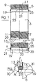
Fig. 1 zeigt zwei zylindrische Rohrelemente eines Rohrsystems nach der Erfindung in einer Seitenansicht in axialer Ausrichtung vor der Herstellung einer Verbindung zwischen den beiden Rohrelementen, wobei das untere Rohrelement gebrochen und somit nur unvollständig dargestellt ist. -
Fig. 2 zeigt in einer schematischen und gebrochen gezeichneten Längsschnitt-Teildarstellung eine Verbindungsstelle 10 zweier aneinander angeschlossener Rohrelemente. - Die Rohrelemente 3 sind im Wesentlichen identisch aufgebaut und weisen jeweils einen axialen Einsteck-Endabschnitt 5 und einen Aufnahme-Endabschnitt 7 auf. Sämtliche Endabschnitte 5, 7 sind mit Gewinde 9 bzw. 11 versehen und so dimensioniert, dass ein Rohrelement 3 mit seinem Einsteck-Endabschnitt 5 in den Aufnahme-Endabschnitt 7 eines anderen Rohrelementes 3 durch Verschraubung des Außengewindes 9 des Einsteck-Endabschnittes 3 mit dem Innengewinde 11 des Aufnahme-Endabschnittes 7 passend einführbar ist.
- Das Rohrelement 3 weist an der Seite seines Aufnahme-Endabschnitts 7 einen muffenartig aufgeweiteten Randabschnitt 13 auf, welcher mit der Ringschulter 15 einen radialen Vorsprung definiert.
- An dem Einsteck-Endabschnitt 5 weist jedes Rohrelement 3 im Abstand x von dem axialen Rand 17 eine radial nach außen geprägte Sicke 19 auf, die mit ihrer Ringschulter 21 einen weiteren radialen Vorsprung bildet. Wie in
Fig. 1 erkennbar, sollte eine axial an die Sicke 19 angrenzende Dichtungsaufnahmezone 23 gewindefrei gehalten sein. Im Bereich dieser Dichtungsaufnahmezone 23 sitzt eine Elastomer-Ringdichtung 25 am Umfang des Einsteck-Endabschnittes 5 auf dem Rohrelement 3 auf. - Beim Zusammenschrauben der beiden Rohrelemente 3 in Fig. 3 übergreift der muffenartige Randabschnitt 13 des oberen Rohrelements 3 die Dichtung 25 des unteren Rohrabschnitts 3 an deren radialer Außenseite. Die stirnseitige Öffnung des muffenartig aufgeweiteten Randabschnittes 13 ist groß genug, damit sie die Dichtungsaufnahmezone 23 mit Dichtung 25 aufnehmen kann. Vorzugsweise ist die stirnseitige Öffnung des muffenartig aufgeweiteten Randabschnitts 13 so groß, dass sie bei miteinander verbundenen Rohrelementen 3 auch die betreffende Sicke 19 radial außen übergreifen kann, wie dies in
Fig. 2 schematisch angedeutet ist. - Im zusammengeschraubten Zustand bilden die Außenumfangsfläche des Dichtungsaufnahmeabschnitts 23 am Einsteck-Endabschnitt 5 des einen Rohrelements 3 und die Innenumfangsfläche 29 des muffenartig erweiterten Randabschnittes 13 radiale Begrenzungen eines Ringraumes 31, in dem die Dichtung 25 eingesperrt ist. An den axialen Enden ist dieser Ringraum 31 von der in den Figuren nach oben weisenden Ringschulterfläche 21 der Sicke 19 des einen Rohrelements 3 und durch die innere, in den Figuren nach unten weisende Ringschulterfläche 15 des muffenartig aufgeweiteten Randabschnitts 13 begrenzt. Diese Ringschulterflächen 15 und 21 beaufschlagen im zusammengeschraubten Zustand der Endabschnitte 5, 7 die in dem Ringraum 31 eingesperrte Dichtung 25 an deren axial einander abgewandten Seiten. Je weiter der axiale Einsteck-Endabschnitt 5 des einen Rohrelements 3 in den Aufnahme-Endabschnitt 7 des anderen Rohrelements 3 hineingeschraubt wird, desto kleiner wird der Ringraum 31 und desto stärker wird der Quetschdruck auf die Dichtung 25 in dem Ringraum 31. Die Elastomerdichtung 25 kommt dabei in zuverlässig abdichtenden Kontakt mit den Begrenzungsflächen des Ringraums 31, wodurch eine auch unter höheren Drucken gasdichte Verbindung der Rohrelemente 3 an ihrer Verbindungsstelle realisiert ist.
- Vorzugsweise ist die Dichtung 25 aufgrund der Formgebung oder/und Materialzusammensetzung so ausgebildet, dass sie eine starke Neigung zur radialen Ausbauchung aufweist, wenn sie in der in
Fig. 2 angedeuteten Weise bei 15 und 21 an entgegengesetzten Seiten axial belastet wird. Eine solche Ringdichtung könnte beispielsweise ein U-Profil mit radial nach innen weisenden kurzen Schenkeln 35 haben. - Für Temperaturbereiche bis etwa 200°C wird als Dichtungselement 25 eine Elastomeredichtung empfohlen.
- Für Temperaturbereiche oberhalb 200°C kommen vorzugsweise mineralische Dichtungen, keramische Dichtbänder, Graphitschnüre und dgl. als Dichtungen 25 in Frage.
- Das druckdichte Schraubverbindungssystem gemäß
Fig. 1 bietet den Vorteil, dass im Verbindungszustand zweier Rohre 3 das eine Rohr 3 im Rahmen einer Drehwinkeltoleranz relativ zu dem anderen Rohr 3 verdreht werden kann, ohne die Dichtheit der Verbindungsstelle 10 unzulässig zu beeinträchtigen. Die Gewinde 5 und 7 müssen also nicht auf Anschlag miteinander verschraubt sein, um Dichtheit zu gewährleisten. Eine derartige Drehwinkeltoleranz erleichtert die Montage eines Rohrsystems, insbesondere wenn auch Rohrelemente mit radialen Anschlusselementen oder dgl. in das Rohrsystem einbezogen werden sollen. - Alternativ zu den Gewinden 5 und 7 oder zusätzlich dazu könnten der muffenartig aufgeweitete Randabschnitt 13 mit einem Innengewinde und die Sicke 19 mit einem dazu komplementären Außengewinde ausgestaltet sein, so dass es an der in
Fig. 2 bei A angedeuteten Stelle zu einer Verschraubung zweier Rohrelemente 3 kommen könnte.
Claims (10)
- Rohrsystem mit Rohrelementen (3), die in Reihe miteinander verbindbar sind, wobei an der Verbindungsstelle (10) zweier aufeinander folgender Rohrelemente (3) ein erstes der beiden Rohrelemente (3) mit einem axialen Einsteck-Endabschnitt (5) in einen axialen Aufnahme-Endabschnitt (7) des zweiten Rohrelementes (3) eingeführt ist, so dass die Endabschnitte (5, 7) der Rohrelemente (3) im Verbindungsbereich einander radial überlappen,
dadurch gekennzeichnet,
dass die Rohrelemente (3) so dimensioniert sind, dass sie in dem Bereich radialer Überlappung der axialen Endabschnitte (5, 7) an der Verbindungsstelle (10) mit ihren einander gegenüberliegenden Umfangswänden (23, 29) einen Ringraum (31) zur Aufnahme einer Dichtung (25) begrenzen, wobei der Ringraum (31) axial von einem am Einsteck-Endabschnitt (5) vorgesehenen ersten radialen Vorsprung (21) auf einer Seite und von einem am Aufnahme-Endabschnitt vorgesehenen zweiten radialen Vorsprung (15) auf der anderen Seite begrenzt ist, wobei die radialen Vorsprünge (15, 21) in axialer Richtung einander annäherbar sind, um eine in dem Ringraum (31) aufgenommene Dichtung an entgegengesetzten Seiten mit Druck zu beaufschlagen. - Rohrsystem nach Anspruch 1, dadurch gekennzeichnet, dass der axiale Aufnahme-Endabschnitt (7) im Bereich des betreffenden axialen Randes des zweiten Rohrelementes (3) unter Bildung oder Einbeziehung des zweiten radialen Vorsprungs (15) zu einem Abschnitt (13) für die radial äußere Begrenzung des Ringraumes (31) aufgeweitet ist und dass der erste radiale Vorsprung (21) mit Abstand vom betreffenden axialen Rand (17) des ersten Rohrelementes (3) an dem Einsteck-Endabschnitt (5) vorgesehen ist.
- Rohrsystem nach Anspruch 2, dadurch gekennzeichnet, dass der erste radiale Vorsprung (21) durch eine radial nach außen geprägte Sicke (19) gebildet ist.
- Rohrsystem nach einem der vorhergehenden Ansprüche, gekennzeichnet durch eine ringförmige Elastomerdichtung (25) für die Abdichtung der Verbindungsstelle (10) zweier in Reihe aneinander angeschlossener Rohrelemente (3) in dem Ringraum (31) zwischen Einsteck-Endabschnitt (5) und Aufnahme-Endabschnitt (7).
- Rohrsystem nach einem der vorhergehenden Ansprüche, gekennzeichnet durch Mittel (9, 11) zur Sicherung der Verbindung zwischen Einsteck-Endabschnitt (5) des ersten Rohrelements (3) und Aufnahme-Endabschnitt (7) des zweiten Rohrelements (3) gegen axiales Trennen.
- Rohrsystem nach einem der vorhergehenden Ansprüche, dadurch gekennzeichnet, dass die Rohrelemente (3, 3) miteinander verschraubbar sind.
- Rohrsystem nach Anspruch 6, dadurch gekennzeichnet, dass der Einsteck-Endabschnitt (5) mit einem Außengewinde (9) versehen ist und dass der Aufnahme-Endabschnitt (7) ein mit dem Außengewinde (9) verschraubbares Innengewinde (11) aufweist.
- Rohrsystem nach Anspruch 7, dadurch gekennzeichnet, dass die Gewinde (9, 11) durch Sicken in den Rohrelementwänden gebildet sind.
- Rohrsystem nach einem der vorhergehenden Ansprüche, dadurch gekennzeichnet, dass das erste Rohrelement (3) und das zweite Rohrelement (3) jeweils einen Einsteck-Endabschnitt (5) an einem axialen Ende und einen Aufnahme-Endabschnitt (7) an dem anderen axialen Ende aufweisen.
- Rohrsystem nach einem der vorhergehenden Ansprüche, dadurch gekennzeichnet, dass die Rohrelemente (3) aus Metall, insbesondere aus Edelstahl bestehen.
Applications Claiming Priority (3)
| Application Number | Priority Date | Filing Date | Title |
|---|---|---|---|
| DE20210002U | 2002-06-28 | ||
| DE20210002U DE20210002U1 (de) | 2002-06-28 | 2002-06-28 | Rohrsystem mit Rohrelementen |
| PCT/EP2003/006852 WO2004003417A1 (de) | 2002-06-28 | 2003-06-27 | Abdichtung für eine einsteckverbindung bei rohren |
Publications (2)
| Publication Number | Publication Date |
|---|---|
| EP1518069A1 EP1518069A1 (de) | 2005-03-30 |
| EP1518069B1 true EP1518069B1 (de) | 2009-04-22 |
Family
ID=7972633
Family Applications (1)
| Application Number | Title | Priority Date | Filing Date |
|---|---|---|---|
| EP03738096A Expired - Lifetime EP1518069B1 (de) | 2002-06-28 | 2003-06-27 | Abdichtung für eine einsteckverbindung bei rohren |
Country Status (6)
| Country | Link |
|---|---|
| EP (1) | EP1518069B1 (de) |
| AT (2) | AT6389U1 (de) |
| AU (1) | AU2003245996A1 (de) |
| DE (2) | DE20210002U1 (de) |
| DK (1) | DK1518069T3 (de) |
| WO (1) | WO2004003417A1 (de) |
Families Citing this family (1)
| Publication number | Priority date | Publication date | Assignee | Title |
|---|---|---|---|---|
| ES2922901T3 (es) * | 2017-05-29 | 2022-09-21 | Jeremias Espana S A | Tubo para transporte de fluidos y sistema de acoplamiento |
Family Cites Families (9)
| Publication number | Priority date | Publication date | Assignee | Title |
|---|---|---|---|---|
| AT41496B (de) * | 1908-12-16 | 1910-03-25 | Giovanni Stuessi | Webschützenspindel. |
| GB2244773B (en) * | 1990-06-08 | 1994-01-19 | Wavin Bv | Improvements in or relating to pipe assemblies |
| DE4121557A1 (de) * | 1991-06-28 | 1993-01-07 | Schiedel Gmbh & Co | Bausatz aus metallrohren fuer den schornsteinbau, verfahren zum herstellen eines innenrohrstranges mittels des bausatzes sowie anwendungen |
| IT239325Y1 (it) * | 1995-04-21 | 2001-02-26 | Meniflex Srl | Elemento di tubo metallico per canna fumaria |
| DE19547677C2 (de) * | 1995-12-20 | 2000-01-27 | Karl Schraeder Nachf Inh Karl | Kaminrohr für die Schornsteinsanierung |
| DE19547901A1 (de) * | 1995-12-21 | 1997-06-26 | Schmitz Tona Tonwerke | Schornsteinrohr aus keramischem Material |
| US5716078A (en) * | 1996-08-07 | 1998-02-10 | Powers; Ronald L. | Thermoplastic pipe joint |
| DE29715437U1 (de) * | 1997-08-28 | 1997-12-11 | Stahl- und Blechbau Schubert GmbH & Co. KG, 04229 Leipzig | Muffensteckverbindung für Rohre, insbesondere Abgas- und Kaminrohre |
| ATE280357T1 (de) * | 1999-01-14 | 2004-11-15 | Schiedel Gmbh & Co | Innenrohr für einen schornstein |
-
2002
- 2002-06-28 DE DE20210002U patent/DE20210002U1/de not_active Expired - Lifetime
- 2002-08-08 AT AT0053602U patent/AT6389U1/de not_active IP Right Cessation
-
2003
- 2003-06-27 DE DE50311451T patent/DE50311451D1/de not_active Expired - Lifetime
- 2003-06-27 DK DK03738096T patent/DK1518069T3/da active
- 2003-06-27 EP EP03738096A patent/EP1518069B1/de not_active Expired - Lifetime
- 2003-06-27 WO PCT/EP2003/006852 patent/WO2004003417A1/de not_active Ceased
- 2003-06-27 AU AU2003245996A patent/AU2003245996A1/en not_active Abandoned
- 2003-06-27 AT AT03738096T patent/ATE429605T1/de not_active IP Right Cessation
Also Published As
| Publication number | Publication date |
|---|---|
| EP1518069A1 (de) | 2005-03-30 |
| AT6389U1 (de) | 2003-09-25 |
| WO2004003417A1 (de) | 2004-01-08 |
| ATE429605T1 (de) | 2009-05-15 |
| DE50311451D1 (de) | 2009-06-04 |
| AU2003245996A1 (en) | 2004-01-19 |
| DE20210002U1 (de) | 2002-12-19 |
| DK1518069T3 (da) | 2009-08-17 |
Similar Documents
| Publication | Publication Date | Title |
|---|---|---|
| DE69802584T2 (de) | Rohrkupplung | |
| DE69520669T2 (de) | Tiefziehbare schnellkupplung | |
| EP0513292B1 (de) | Rohrverbindung, insbesondere an verbundrohren | |
| DE60037440T2 (de) | Vorrichtung zum verbinden rohrförmiger körper | |
| DE2856064C2 (de) | ||
| DE2058203C2 (de) | Rohrverbinder | |
| EP0806597A1 (de) | Schnellkupplung | |
| DE10017221A1 (de) | Dichtungs-Ring für Verbindung zwischen Spitzende eines Wellrohres und Rohr-Muffe mit glatter Innenwand | |
| DE3317061A1 (de) | Flanschverbindungsanordnung | |
| WO2006018384A1 (de) | Steckverbindung für fluid-leitungen | |
| EP3066375B1 (de) | Vorrichtung zum koaxialen verbinden zweier rohrleitungen und anordnung zum lösen | |
| EP1673185B1 (de) | Verfahren und vorrichtung zur herstellung einer rohrpressverbindung an einer steckverbindung | |
| DE19548249A1 (de) | Steckstück | |
| EP3645926A1 (de) | Presshülse | |
| EP4158233B1 (de) | Steckverbinder sowie daraus gebildete steckerbaugruppe | |
| EP1092906A1 (de) | Dichtungsring für ein mit äusseren Wellen versehenes Kunststoffrohr | |
| EP1518069B1 (de) | Abdichtung für eine einsteckverbindung bei rohren | |
| EP1006307B1 (de) | Steckkupplung | |
| DE4310795C1 (de) | Steckkupplung | |
| EP1944536A2 (de) | Presshülse für eine Pressverbindung von Rohren | |
| EP3501620A1 (de) | Stützring für die befestigung eines filtertuchs an einem filterelement | |
| EP2650576B1 (de) | Doppelnippel zur abgedichteten Verlegung von Langformteilen | |
| DE19509579C2 (de) | Rohrelement zum Erstellen von Schornsteinen sowie von Abgas- und Abdampfleitungen | |
| EP4382793B1 (de) | Klemmvorrichtung zur axialsicherung einer muffenrohrverbindung und muffenrohrverbindung samt einer entsprechenden klemmvorrichtung | |
| EP4560173B1 (de) | Steckkupplung |
Legal Events
| Date | Code | Title | Description |
|---|---|---|---|
| PUAI | Public reference made under article 153(3) epc to a published international application that has entered the european phase |
Free format text: ORIGINAL CODE: 0009012 |
|
| 17P | Request for examination filed |
Effective date: 20041117 |
|
| AK | Designated contracting states |
Kind code of ref document: A1 Designated state(s): AT BE BG CH CY CZ DE DK EE ES FI FR GB GR HU IE IT LI LU MC NL PT RO SE SI SK TR |
|
| AX | Request for extension of the european patent |
Extension state: AL LT LV MK |
|
| DAX | Request for extension of the european patent (deleted) | ||
| GRAP | Despatch of communication of intention to grant a patent |
Free format text: ORIGINAL CODE: EPIDOSNIGR1 |
|
| GRAS | Grant fee paid |
Free format text: ORIGINAL CODE: EPIDOSNIGR3 |
|
| GRAA | (expected) grant |
Free format text: ORIGINAL CODE: 0009210 |
|
| AK | Designated contracting states |
Kind code of ref document: B1 Designated state(s): AT BE BG CH CY CZ DE DK EE ES FI FR GB GR HU IE IT LI LU MC NL PT RO SE SI SK TR |
|
| REG | Reference to a national code |
Ref country code: GB Ref legal event code: FG4D Free format text: NOT ENGLISH |
|
| REG | Reference to a national code |
Ref country code: CH Ref legal event code: EP |
|
| REG | Reference to a national code |
Ref country code: IE Ref legal event code: FG4D |
|
| REF | Corresponds to: |
Ref document number: 50311451 Country of ref document: DE Date of ref document: 20090604 Kind code of ref document: P |
|
| REG | Reference to a national code |
Ref country code: CH Ref legal event code: NV Representative=s name: BOHEST AG |
|
| REG | Reference to a national code |
Ref country code: DK Ref legal event code: T3 |
|
| PG25 | Lapsed in a contracting state [announced via postgrant information from national office to epo] |
Ref country code: PT Free format text: LAPSE BECAUSE OF FAILURE TO SUBMIT A TRANSLATION OF THE DESCRIPTION OR TO PAY THE FEE WITHIN THE PRESCRIBED TIME-LIMIT Effective date: 20090822 Ref country code: ES Free format text: LAPSE BECAUSE OF FAILURE TO SUBMIT A TRANSLATION OF THE DESCRIPTION OR TO PAY THE FEE WITHIN THE PRESCRIBED TIME-LIMIT Effective date: 20090802 Ref country code: FI Free format text: LAPSE BECAUSE OF FAILURE TO SUBMIT A TRANSLATION OF THE DESCRIPTION OR TO PAY THE FEE WITHIN THE PRESCRIBED TIME-LIMIT Effective date: 20090422 |
|
| PG25 | Lapsed in a contracting state [announced via postgrant information from national office to epo] |
Ref country code: SE Free format text: LAPSE BECAUSE OF FAILURE TO SUBMIT A TRANSLATION OF THE DESCRIPTION OR TO PAY THE FEE WITHIN THE PRESCRIBED TIME-LIMIT Effective date: 20090722 Ref country code: SI Free format text: LAPSE BECAUSE OF FAILURE TO SUBMIT A TRANSLATION OF THE DESCRIPTION OR TO PAY THE FEE WITHIN THE PRESCRIBED TIME-LIMIT Effective date: 20090422 |
|
| REG | Reference to a national code |
Ref country code: IE Ref legal event code: FD4D |
|
| PG25 | Lapsed in a contracting state [announced via postgrant information from national office to epo] |
Ref country code: IE Free format text: LAPSE BECAUSE OF FAILURE TO SUBMIT A TRANSLATION OF THE DESCRIPTION OR TO PAY THE FEE WITHIN THE PRESCRIBED TIME-LIMIT Effective date: 20090422 Ref country code: MC Free format text: LAPSE BECAUSE OF NON-PAYMENT OF DUE FEES Effective date: 20090630 Ref country code: RO Free format text: LAPSE BECAUSE OF FAILURE TO SUBMIT A TRANSLATION OF THE DESCRIPTION OR TO PAY THE FEE WITHIN THE PRESCRIBED TIME-LIMIT Effective date: 20090422 Ref country code: EE Free format text: LAPSE BECAUSE OF FAILURE TO SUBMIT A TRANSLATION OF THE DESCRIPTION OR TO PAY THE FEE WITHIN THE PRESCRIBED TIME-LIMIT Effective date: 20090422 Ref country code: CZ Free format text: LAPSE BECAUSE OF FAILURE TO SUBMIT A TRANSLATION OF THE DESCRIPTION OR TO PAY THE FEE WITHIN THE PRESCRIBED TIME-LIMIT Effective date: 20090422 |
|
| PG25 | Lapsed in a contracting state [announced via postgrant information from national office to epo] |
Ref country code: SK Free format text: LAPSE BECAUSE OF FAILURE TO SUBMIT A TRANSLATION OF THE DESCRIPTION OR TO PAY THE FEE WITHIN THE PRESCRIBED TIME-LIMIT Effective date: 20090422 |
|
| PLBE | No opposition filed within time limit |
Free format text: ORIGINAL CODE: 0009261 |
|
| STAA | Information on the status of an ep patent application or granted ep patent |
Free format text: STATUS: NO OPPOSITION FILED WITHIN TIME LIMIT |
|
| 26N | No opposition filed |
Effective date: 20100125 |
|
| PG25 | Lapsed in a contracting state [announced via postgrant information from national office to epo] |
Ref country code: BG Free format text: LAPSE BECAUSE OF FAILURE TO SUBMIT A TRANSLATION OF THE DESCRIPTION OR TO PAY THE FEE WITHIN THE PRESCRIBED TIME-LIMIT Effective date: 20090722 |
|
| PG25 | Lapsed in a contracting state [announced via postgrant information from national office to epo] |
Ref country code: GR Free format text: LAPSE BECAUSE OF FAILURE TO SUBMIT A TRANSLATION OF THE DESCRIPTION OR TO PAY THE FEE WITHIN THE PRESCRIBED TIME-LIMIT Effective date: 20090723 |
|
| PGFP | Annual fee paid to national office [announced via postgrant information from national office to epo] |
Ref country code: CH Payment date: 20100812 Year of fee payment: 8 Ref country code: NL Payment date: 20100813 Year of fee payment: 8 |
|
| PGFP | Annual fee paid to national office [announced via postgrant information from national office to epo] |
Ref country code: AT Payment date: 20100812 Year of fee payment: 8 Ref country code: FR Payment date: 20100824 Year of fee payment: 8 Ref country code: IT Payment date: 20100730 Year of fee payment: 8 Ref country code: LU Payment date: 20100812 Year of fee payment: 8 |
|
| PGFP | Annual fee paid to national office [announced via postgrant information from national office to epo] |
Ref country code: GB Payment date: 20100730 Year of fee payment: 8 |
|
| PGFP | Annual fee paid to national office [announced via postgrant information from national office to epo] |
Ref country code: DK Payment date: 20100810 Year of fee payment: 8 |
|
| PGFP | Annual fee paid to national office [announced via postgrant information from national office to epo] |
Ref country code: BE Payment date: 20100729 Year of fee payment: 8 |
|
| PG25 | Lapsed in a contracting state [announced via postgrant information from national office to epo] |
Ref country code: HU Free format text: LAPSE BECAUSE OF FAILURE TO SUBMIT A TRANSLATION OF THE DESCRIPTION OR TO PAY THE FEE WITHIN THE PRESCRIBED TIME-LIMIT Effective date: 20091023 |
|
| PG25 | Lapsed in a contracting state [announced via postgrant information from national office to epo] |
Ref country code: TR Free format text: LAPSE BECAUSE OF FAILURE TO SUBMIT A TRANSLATION OF THE DESCRIPTION OR TO PAY THE FEE WITHIN THE PRESCRIBED TIME-LIMIT Effective date: 20090422 |
|
| PG25 | Lapsed in a contracting state [announced via postgrant information from national office to epo] |
Ref country code: CY Free format text: LAPSE BECAUSE OF FAILURE TO SUBMIT A TRANSLATION OF THE DESCRIPTION OR TO PAY THE FEE WITHIN THE PRESCRIBED TIME-LIMIT Effective date: 20090422 |
|
| BERE | Be: lapsed |
Owner name: JOSEPH RAAB G.M.B.H. & CIE. KG Effective date: 20110630 |
|
| REG | Reference to a national code |
Ref country code: NL Ref legal event code: V1 Effective date: 20120101 |
|
| REG | Reference to a national code |
Ref country code: CH Ref legal event code: PL |
|
| REG | Reference to a national code |
Ref country code: DK Ref legal event code: EBP |
|
| GBPC | Gb: european patent ceased through non-payment of renewal fee |
Effective date: 20110627 |
|
| PG25 | Lapsed in a contracting state [announced via postgrant information from national office to epo] |
Ref country code: IT Free format text: LAPSE BECAUSE OF NON-PAYMENT OF DUE FEES Effective date: 20110627 Ref country code: AT Free format text: LAPSE BECAUSE OF NON-PAYMENT OF DUE FEES Effective date: 20110627 |
|
| REG | Reference to a national code |
Ref country code: AT Ref legal event code: MM01 Ref document number: 429605 Country of ref document: AT Kind code of ref document: T Effective date: 20110627 |
|
| REG | Reference to a national code |
Ref country code: FR Ref legal event code: ST Effective date: 20120229 |
|
| PG25 | Lapsed in a contracting state [announced via postgrant information from national office to epo] |
Ref country code: BE Free format text: LAPSE BECAUSE OF NON-PAYMENT OF DUE FEES Effective date: 20110630 |
|
| PG25 | Lapsed in a contracting state [announced via postgrant information from national office to epo] |
Ref country code: LI Free format text: LAPSE BECAUSE OF NON-PAYMENT OF DUE FEES Effective date: 20110630 Ref country code: FR Free format text: LAPSE BECAUSE OF NON-PAYMENT OF DUE FEES Effective date: 20110630 Ref country code: CH Free format text: LAPSE BECAUSE OF NON-PAYMENT OF DUE FEES Effective date: 20110630 |
|
| PG25 | Lapsed in a contracting state [announced via postgrant information from national office to epo] |
Ref country code: NL Free format text: LAPSE BECAUSE OF NON-PAYMENT OF DUE FEES Effective date: 20120101 |
|
| PG25 | Lapsed in a contracting state [announced via postgrant information from national office to epo] |
Ref country code: GB Free format text: LAPSE BECAUSE OF NON-PAYMENT OF DUE FEES Effective date: 20110627 |
|
| PG25 | Lapsed in a contracting state [announced via postgrant information from national office to epo] |
Ref country code: DK Free format text: LAPSE BECAUSE OF NON-PAYMENT OF DUE FEES Effective date: 20110630 |
|
| PGFP | Annual fee paid to national office [announced via postgrant information from national office to epo] |
Ref country code: DE Payment date: 20120629 Year of fee payment: 10 |
|
| PG25 | Lapsed in a contracting state [announced via postgrant information from national office to epo] |
Ref country code: LU Free format text: LAPSE BECAUSE OF NON-PAYMENT OF DUE FEES Effective date: 20110627 |
|
| REG | Reference to a national code |
Ref country code: DE Ref legal event code: R119 Ref document number: 50311451 Country of ref document: DE Effective date: 20140101 |
|
| PG25 | Lapsed in a contracting state [announced via postgrant information from national office to epo] |
Ref country code: DE Free format text: LAPSE BECAUSE OF NON-PAYMENT OF DUE FEES Effective date: 20140101 |