EP1517771B1 - Appareil permettant de realiser une coupe a rupture entre le capuchon et la bague d'inviolabilite de capsules en plastique - Google Patents
Appareil permettant de realiser une coupe a rupture entre le capuchon et la bague d'inviolabilite de capsules en plastique Download PDFInfo
- Publication number
- EP1517771B1 EP1517771B1 EP03740958A EP03740958A EP1517771B1 EP 1517771 B1 EP1517771 B1 EP 1517771B1 EP 03740958 A EP03740958 A EP 03740958A EP 03740958 A EP03740958 A EP 03740958A EP 1517771 B1 EP1517771 B1 EP 1517771B1
- Authority
- EP
- European Patent Office
- Prior art keywords
- cup
- carousel
- mandrel
- respect
- axis
- Prior art date
- Legal status (The legal status is an assumption and is not a legal conclusion. Google has not performed a legal analysis and makes no representation as to the accuracy of the status listed.)
- Expired - Lifetime
Links
Images

Classifications
-
- B—PERFORMING OPERATIONS; TRANSPORTING
- B26—HAND CUTTING TOOLS; CUTTING; SEVERING
- B26D—CUTTING; DETAILS COMMON TO MACHINES FOR PERFORATING, PUNCHING, CUTTING-OUT, STAMPING-OUT OR SEVERING
- B26D7/00—Details of apparatus for cutting, cutting-out, stamping-out, punching, perforating, or severing by means other than cutting
- B26D7/06—Arrangements for feeding or delivering work of other than sheet, web, or filamentary form
- B26D7/0608—Arrangements for feeding or delivering work of other than sheet, web, or filamentary form by pushers
-
- B—PERFORMING OPERATIONS; TRANSPORTING
- B26—HAND CUTTING TOOLS; CUTTING; SEVERING
- B26D—CUTTING; DETAILS COMMON TO MACHINES FOR PERFORATING, PUNCHING, CUTTING-OUT, STAMPING-OUT OR SEVERING
- B26D1/00—Cutting through work characterised by the nature or movement of the cutting member or particular materials not otherwise provided for; Apparatus or machines therefor; Cutting members therefor
- B26D1/01—Cutting through work characterised by the nature or movement of the cutting member or particular materials not otherwise provided for; Apparatus or machines therefor; Cutting members therefor involving a cutting member which does not travel with the work
- B26D1/02—Cutting through work characterised by the nature or movement of the cutting member or particular materials not otherwise provided for; Apparatus or machines therefor; Cutting members therefor involving a cutting member which does not travel with the work having a stationary cutting member
-
- B—PERFORMING OPERATIONS; TRANSPORTING
- B26—HAND CUTTING TOOLS; CUTTING; SEVERING
- B26F—PERFORATING; PUNCHING; CUTTING-OUT; STAMPING-OUT; SEVERING BY MEANS OTHER THAN CUTTING
- B26F2210/00—Perforating, punching, cutting-out, stamping-out, severing by means other than cutting of specific products
- B26F2210/04—Making plastic pilferproof screw caps by cutting a tamper ring
-
- Y—GENERAL TAGGING OF NEW TECHNOLOGICAL DEVELOPMENTS; GENERAL TAGGING OF CROSS-SECTIONAL TECHNOLOGIES SPANNING OVER SEVERAL SECTIONS OF THE IPC; TECHNICAL SUBJECTS COVERED BY FORMER USPC CROSS-REFERENCE ART COLLECTIONS [XRACs] AND DIGESTS
- Y10—TECHNICAL SUBJECTS COVERED BY FORMER USPC
- Y10S—TECHNICAL SUBJECTS COVERED BY FORMER USPC CROSS-REFERENCE ART COLLECTIONS [XRACs] AND DIGESTS
- Y10S425/00—Plastic article or earthenware shaping or treating: apparatus
- Y10S425/809—Seal, bottle caps only
-
- Y—GENERAL TAGGING OF NEW TECHNOLOGICAL DEVELOPMENTS; GENERAL TAGGING OF CROSS-SECTIONAL TECHNOLOGIES SPANNING OVER SEVERAL SECTIONS OF THE IPC; TECHNICAL SUBJECTS COVERED BY FORMER USPC CROSS-REFERENCE ART COLLECTIONS [XRACs] AND DIGESTS
- Y10—TECHNICAL SUBJECTS COVERED BY FORMER USPC
- Y10S—TECHNICAL SUBJECTS COVERED BY FORMER USPC CROSS-REFERENCE ART COLLECTIONS [XRACs] AND DIGESTS
- Y10S83/00—Cutting
- Y10S83/929—Particular nature of work or product
- Y10S83/946—Container
-
- Y—GENERAL TAGGING OF NEW TECHNOLOGICAL DEVELOPMENTS; GENERAL TAGGING OF CROSS-SECTIONAL TECHNOLOGIES SPANNING OVER SEVERAL SECTIONS OF THE IPC; TECHNICAL SUBJECTS COVERED BY FORMER USPC CROSS-REFERENCE ART COLLECTIONS [XRACs] AND DIGESTS
- Y10—TECHNICAL SUBJECTS COVERED BY FORMER USPC
- Y10T—TECHNICAL SUBJECTS COVERED BY FORMER US CLASSIFICATION
- Y10T82/00—Turning
- Y10T82/16—Severing or cut-off
- Y10T82/16426—Infeed means
- Y10T82/16967—Infeed means with means to support and/or rotate work
-
- Y—GENERAL TAGGING OF NEW TECHNOLOGICAL DEVELOPMENTS; GENERAL TAGGING OF CROSS-SECTIONAL TECHNOLOGIES SPANNING OVER SEVERAL SECTIONS OF THE IPC; TECHNICAL SUBJECTS COVERED BY FORMER USPC CROSS-REFERENCE ART COLLECTIONS [XRACs] AND DIGESTS
- Y10—TECHNICAL SUBJECTS COVERED BY FORMER USPC
- Y10T—TECHNICAL SUBJECTS COVERED BY FORMER US CLASSIFICATION
- Y10T83/00—Cutting
- Y10T83/02—Other than completely through work thickness
- Y10T83/0333—Scoring
-
- Y—GENERAL TAGGING OF NEW TECHNOLOGICAL DEVELOPMENTS; GENERAL TAGGING OF CROSS-SECTIONAL TECHNOLOGIES SPANNING OVER SEVERAL SECTIONS OF THE IPC; TECHNICAL SUBJECTS COVERED BY FORMER USPC CROSS-REFERENCE ART COLLECTIONS [XRACs] AND DIGESTS
- Y10—TECHNICAL SUBJECTS COVERED BY FORMER USPC
- Y10T—TECHNICAL SUBJECTS COVERED BY FORMER US CLASSIFICATION
- Y10T83/00—Cutting
- Y10T83/202—With product handling means
- Y10T83/2092—Means to move, guide, or permit free fall or flight of product
- Y10T83/22—Means to move product laterally
-
- Y—GENERAL TAGGING OF NEW TECHNOLOGICAL DEVELOPMENTS; GENERAL TAGGING OF CROSS-SECTIONAL TECHNOLOGIES SPANNING OVER SEVERAL SECTIONS OF THE IPC; TECHNICAL SUBJECTS COVERED BY FORMER USPC CROSS-REFERENCE ART COLLECTIONS [XRACs] AND DIGESTS
- Y10—TECHNICAL SUBJECTS COVERED BY FORMER USPC
- Y10T—TECHNICAL SUBJECTS COVERED BY FORMER US CLASSIFICATION
- Y10T83/00—Cutting
- Y10T83/929—Tool or tool with support
- Y10T83/9372—Rotatable type
Definitions
- the present invention relates to an apparatus for making a fracture cut between the cup and the safety ring in plastic caps.
- Apparatuses which produce, on the side wall of plastic caps, a circumferential fracture cut that forms the safety ring that remains attached to the container after tearing the cup from the cap: for this purpose, inside the cup there are retention elements, obtained for example by folding inward the end flap of the ring, which are suitable to engage on the protruding collar provided on the neck of the container.
- the fracture cut is generally provided by rolling the lateral surface of the cap along a blade whose cutting edge is perpendicular to the axis of said cap by means of a mandrel that engages within the cup.
- the mandrel is substantially axially offset with respect to the cup, since the blade is associated with an inlet portion that is suitable to move said cup with respect to the axis of the mandrel: in rolling the cap, the side wall of the cup is therefore kept pressed by the mandrel against the cutting edge of the blade, thus providing the cut.
- the cup At the end of the cap rolling step it is necessary to reposition the cup in axial alignment with respect to the mandrel, so as to be able to proceed correctly with the subsequent operations of the production process: for example, the cup must be removable from the mandrel without encountering the obstacle constituted by the undercuts formed by the presence of the retention elements within said cup.
- the technical aim of the present invention is to provide an apparatus for making a fracture cut between the cup and the safety ring in plastic caps that allows, after forming said cut, to reposition the cup in axial alignment with respect to the mandrel inserted therein.
- an object of the present invention is to provide an apparatus that is versatile and adaptable to caps of various shapes and dimensions.
- Another object of the present invention is to achieve said aim with a structure that is simple, relatively easy to provide in practice, safe in use, effective in operation, and relatively low in cost.
- the present apparatus which comprises rotary means provided with at least one mandrel that can be arranged inside said cup and is adapted to produce the rolling, about its own axis of symmetry, of the side wall of said cup along the cutting edge of a blade for making said cut, said blade being associated with an inlet path portion adapted to axially offset said cup with respect to the rotation axis of said mandrel by clamping said side wall against said mandrel, and comprises means for recentering said cup with respect to said rotation axis.
- said rotary means are driven by a motor by way of belt drive elements.
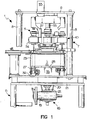
- the reference numeral 1 generally designates an apparatus for making a fracture cut between the cup and the sealing ring in plastic caps 2 according to the invention.
- the apparatus of the type suitable to make a fracture cut between the cup 3 and the sealing ring 4 in caps 2 to be applied so as to close containers (the cup 3 being preferably provided with internal retention elements 5 for engagement on a collar provided on the respective container), comprises a footing 6, which protrudes upward with a substantially vertical frame 7 that is constituted by parallel uprights 8 that support a beam 9 (see Figure 1 ).
- the footing 6 rotatably supports a rotary carousel 10, which has a vertical axis and is preset to convey continuously the caps 2 between input and output conveyance means, not shown in the figures.
- the footing 6 furthermore supports rotary means 11, which are provided with a plurality of mandrels 12 that have a vertical axis; each mandrel can be arranged inside a respective cup 3 and is suitable to roll, about its own axis of symmetry S, the side wall 13 of said cups 3 along the cutting edge 14 of a blade 15 for making the circumferential fracture cut on said side wall 13.
- the blade 15 is associated with an inlet path portion 16 for the cups 3, which is adjacent thereto and is suitable to axially offset each cup 3 with respect to the rotation axis R of the respective mandrel 12, so as to clamp the side wall 13 between said cutting edge 14 and the mandrel 12.
- the apparatus comprises means 17 for recentering each cup 3 with respect to the rotation axis R of the respective mandrel 12 once the fracture cut has been made.
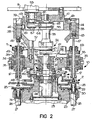
- the carousel 10 is associated with means for continuous rotary actuation 18, which are constituted by a gearmotor 19 that is fixed by means of a flange 20 to parts 21 of the footing and has a vertical output shaft 22 that is rigidly connected so that it is coaxial to said carousel 10.
- the carousel 10 comprises ( Figure 2 ) a first drum 23, which is provided internally with an axial through cavity 24 and is connected in a downward region to a flanged shaft 25 that is connected to the output shaft 22 of the gearmotor 19 and is affected by multiple peripheral through holes 26 that have a vertical axis and are angularly equidistant for the sliding insertion of respective pillars 27 provided at their upper ends with seats for conveying the caps 2; the seats are preferably constituted by disk-like plates 28, which extend downward with respective stems 29 supported by thrust bearings 30 mounted within respective receptacles 31 provided in the pillars 27.
- the pillars 27 can be actuated so as to rise from a lower position to an upper position and have respective rollers 32 fixed to their respective lower ends, said rollers being engaged within an annular cam 33 that is coaxial to the extension 25 and monolithic with the footing 6.
- Multiple lateral through slots 33a are further provided on the first drum 23 and are mutually angularly equidistant.
- the first drum 23 is surmounted by a second drum 34, which is rigidly coupled thereto, is substantially annular and is provided with a plurality of cylindrical through seats 35 that have a vertical axis, each seat being coaxial to a respective through hole 26 of the first drum 23: a respective cylindrical bush 36 is locked in each seat 35.
- a support 37 is rigidly fixed to the second drum 34 and is constituted by multiple peripheral arms 38, which are extended vertically and are mutually angularly equidistant: each one of the arms 38 is affected by a respective slot 39, which corresponds to a respective seat 35 of the second drum 34.
- a vertical column 40, rigidly coupled to the footing 6, is inserted coaxially through the first and second drums 23 and 34; a substantially disk-like dome 41 is keyed to the top of the column 40 and is provided, in an upward region, with an opening 42 and has, on its lateral surface, a cylindrical cam 43 with a rolling track that has a rectangular transverse cross-section.
- the rotary means 11 comprise a sliding block 44, which is provided with a lateral wheel 45 that engages in the cylindrical cam 43; the sliding block 44 is extended downward with a fixing bracket 46 for a rod 47, which is coupled elastically thereto with the interposition of a helical spring 48, which is inserted loosely in an elongated tubular body 49, which is supported so that it can rotate within the corresponding bush 36 and whose lower end ends with a substantially disk-like pad 50.
- Each tubular body 49 has the respective mandrel 12 rigidly coupled thereto in a downward region; said mandrel is provided with an axial hole for the passage of the respective rod 47 and has, at its base, a cylindrical hollow 51 ( Figure 4 ); the mandrel 12 is preferably provided, on its lateral surface, with a distribution of collars 52 for the abutment of the retention elements 5 of the cup.
- the rotary means 11 are actuated by a motor 53, for example of the brushless type and provided with a vertical axis, by way of belt drive elements 54.
- the belt drive elements 54 comprise a sleeve 55, which is supported so that it can rotate along the column 40 and is actuated by the motor 53 at the respective upper end 56; a first toothed pulley 58 and a second toothed pulley 59 are keyed to said sleeve at its respective lower end 57, and a first toothed belt 60 and a second toothed belt 61 are wound around said first and second pulleys respectively, said belts being closed in a loop and being suitable for the rotary actuation of the mandrels 12: the first and second belts 60, 61 are wound, with the aid of suitable tensioning rollers 62, around respective driven pulleys 63, which are keyed to the top of the respective tubular bodies 49.
- a third toothed pulley 64 is keyed at the upper end 56 of the sleeve 55, and a third toothed belt 65 is wound around said third pulley; said third belt is closed in a loop and is suitable for connection to the motor 53; a driving pulley 67 is keyed on the output shaft 66 of the motor 53, and the third toothed belt 65 is wound thereon.
- the output shaft 66 passes through the opening 42 of the dome 41, and its axis is parallel to the axis of the sleeve 55; as an alternative, it is noted that the motor 53 can be connected coaxially directly to the sleeve 55.
- the recentering means 17 comprise multiple pushers 68, each of which acts on the side wall 13 of the respective cup 3 in a direction that is substantially radial and centrifugal with respect to the axis of the carousel 10: the pushers 68 can be actuated by way of respective cam means 69.
- Each one of the pushers 68 is preferably substantially quadrangular, with a slightly convex surface 70 for contact with the respective cup 3 ( Figure 3 ); the pusher 68 is connected to an arm 71 that continues with a stem 72 that can slide, in a substantially radial direction with respect to the carousel 10, within a respective guiding block 73, which is inserted in a respective slot 33a.
- a wheel provided with a vertical axis 74 is supported so that it can rotate at right angles at the free end of each stem 72;
- the cam means 69 are constituted by a flat track 75, which is closed in a loop and is provided in the lower face of a bush 76 that is fixed coaxially to the carousel 10 along the column 40.
- the track 75 is suitable for the rolling of the wheels 74 having a vertical axis, causing the radial translational motion of the respective pushers 68 in order to move each cup 3 centrifugally, moving the axis of symmetry S of said cup 3 so that it coincides with the rotation axis R of the respective mandrel 13.
- peripheral abutment element 77 for the cups 3 moved by the respective pushers 68 which comprises a supporting bracket 78 that has an elongated shape and ends with an L-shaped portion 79 that can be adjusted radially with respect to the carousel 10 according to the dimensions of the cups 3.
- the blade 15 is packed between a lower reference plate 80 and an upper complementary plate 81, which is locked thereat by virtue of suitable fixing means 82 (for example of the clamp type): the cutting edge 14 has a profile that is shaped substantially like a circular arc that is concentric with respect to the rotational path T of each cup 3 on the carousel 10.
- the inlet portion 16 is formed on the plate 80 and the complementary plate 81 and is shaped so as to provide an axial offset of the cup 3 in its rolling motion with respect to the rotation axis R of the respective mandrel 13.
- each cap 2 is locked on the carousel 10 between the plate 28 and the pad 50, said pad 50 being actuated so as to descend by virtue of the rolling of the respective lateral wheel 45 in the cylindrical cam 43, the plate 28 being actuated so as to rise to the plane of the blade 15 by virtue of the rolling of the respective roller 32 along the annular cam 33; the presence of the helical spring 48 allows to compensate for even slight size differences among the various caps arising from any manufacturing imperfections.
- each cup 3 has its own axis of symmetry S, which is substantially parallel to the rotation axis R of the respective mandrel 12 after passing over the inlet portion 16, allows to make the fracture cut along the side wall 13, which is clamped between said mandrel 12 and the blade 15 (see Figure 4 ).
- the cam means 69 induce the centrifugal radial translational motion of the corresponding stem 72 and therefore of the pusher 68, which by acting on the side wall 13 of the cup 3 makes its axis of symmetry S coincide again with the rotation axis R of the respective mandrel 12; this occurs with the aid of the abutment element 77, which stops precisely the radial movement of the cup 3 ( Figure 3 ).
- the apparatus according to the invention ensures, at the end of the provision of the fracture cut, an effective recentering of the cup 3 with respect to the rotation axis R of the mandrel 12; this operation, moreover, can be performed in a very versatile manner with caps 2 of various shapes and dimensions.
Landscapes
- Forests & Forestry (AREA)
- Engineering & Computer Science (AREA)
- Mechanical Engineering (AREA)
- Life Sciences & Earth Sciences (AREA)
- Closures For Containers (AREA)
- Closing Of Containers (AREA)
- Crushing And Grinding (AREA)
- Measuring Or Testing Involving Enzymes Or Micro-Organisms (AREA)
- Package Frames And Binding Bands (AREA)
- Crushing And Pulverization Processes (AREA)
- Apparatus For Making Beverages (AREA)
- Devices For Opening Bottles Or Cans (AREA)
- Nonmetal Cutting Devices (AREA)
- Perforating, Stamping-Out Or Severing By Means Other Than Cutting (AREA)
Claims (7)
- Appareil permettant de réaliser une coupe à rupture entre le capuchon et la bague d'inviolabilité de capsules en plastique, comportant des moyens rotatifs (11) munis d'au moins un mandrin (12) pouvant être placé à l'intérieur dudit capuchon (3) et adapté pour entraîner la rotation autour de son propre axe de symétrie (S), de la paroi latérale (13) dudit capuchon (3) le long de l'arête de coupe (14) d'une lame (15) permettant de réaliser ladite coupe, ladite lame (15) étant associée à une partie de voie d'entrée (16) adaptée pour décaler axialement ledit capuchon (3) par rapport à l'axe de rotation (5) dudit mandrin (12) par serrage de ladite paroi latérale (13) contre ledit mandarin (12), l'appareil comportant un carrousel (10) qui a un axe vertical et est muni de multiples supports (28) pour acheminer lesdits capuchons (3) entre des moyens d'acheminement d'entrée et de sortie, l'appareil comportant en outre une semelle (6) qui s'étend vers le haut avec un châssis (7) qui surmonte ledit carrousel (10), lesdits moyens rotatifs (11) étant actionnés par un moteur respectif (53), caractérisé en ce que le carrousel (10) comporte des moyens (17) servant à recentrer ledit capuchon (3) par rapport à l'axe de rotation (R).
- Appareil selon la revendication 1, caractérisé en ce que lesdits moyens de recentrage (17) comportent de multiples poussoirs (68), lesquels agissent sur ladite paroi latérale (13) de chacun desdits capuchons (3) dans une direction qui est sensiblement radiale et centrifuge par rapport audit carrousel (10), et sont actionnés par des moyens à came respectifs (69).
- Appareil selon une ou plusieurs des revendications précédentes, caractérisé en ce que chacun desdits poussoirs (68) a une forme en grande partie quadrangulaire, la surface (70) pour le contact avec lesdits capuchons (3) étant convexe, ledit poussoir (68) étant replié à un bras (71) qui s'étend à l'aide d'une tige (112) laquelle peut coulisser en grande partie radialement par rapport audit carrousel (10) dans un bloc de guidage respectif (73), ladite tige (72) étant reliée au niveau de son extrémité libre à une roue respective (74), lesdits moyens à came (69) comportant un chemin de roulement (75) qui est fermé dans une boucle et est agencé sur une douille (76) qui est coaxiale audit carrousel (10) et est monolithique avec ladite semelle (6), ledit chemin de roulement étant adapté pour la rotation de ladite roue (74) et ayant une forme de manière à produire le déplacement par translation radiale dudit poussoir (68).
- Appareil selon une ou plusieurs de revendications précédentes, caractérisé en ce que les éléments d'entraînement de courroie (54) comportent un manchon (55) lequel est supporté de sorte qu'il peut pivoter sur une colonne (40) qui est coaxiale audit carrousel (10), est couplé de manière rigide à ladite semelle (6), est actionné au niveau de l'extrémité supérieure respective (56) par l'intermédiaire dudit moteur (53), et sur lequel des première et seconde poulies dentées coaxiales (58, 59) sont clavetées au niveau de l'extrémité inférieure respective (57), des première et seconde courroies dentées (60, 61) étant enroulés respectivement autour desdites poulies, lesdites courroies étant fermées dans une boucle et étant adaptées pour l'actionnement rotatif d'une pluralité desdits mandrins (12) qui ont un axe vertical.
- Appareil selon une ou plusieurs des revendications précédentes, caractérisé en ce que ledit moteur (53) est relié de manière coaxiale à ladite extrémité supérieure (56) dudit manchon (55).
- Appareil selon une ou plusieurs des revendications précédentes, caractérisé en ce que une troisième poulie dentée (64) est clavetée au niveau de ladite extrémité supérieure (56) dudit manchon (55), une troisième courroie dentée respective (65) étant enroulée autour de ladite troisième poulie, ladite troisième courroie étant fermée dans une boucle et adaptée en vue d'une connexion audit moteur (53), dont l'axe est parallèle à l'axe dudit manchon (55).
- Appareil selon une ou plusieurs des revendications précédentes, caractérisé en ce que ladite arrête de coupe (14) de ladite lame (15) à un profil qui est en grande partie mis en forme comme un are circulaire qui est concentrique par rapport au trajet (T) de la rotation desdits capuchons (3) acheminés par ledit carrousel (10), ladite partie d'entrée (16) étant formée par une plaque (80) et une plaque complémentaire (81) pour supporter ladite lame (15).
Applications Claiming Priority (3)
| Application Number | Priority Date | Filing Date | Title |
|---|---|---|---|
| IT2002BO000422A ITBO20020422A1 (it) | 2002-07-02 | 2002-07-02 | Macchina per effettuare un'incisione di frattura tra lo scodellino e l'anello di garanzia in capsule di materiale plastico |
| ITBO20020422 | 2002-07-02 | ||
| PCT/IB2003/003053 WO2004004993A1 (fr) | 2002-07-02 | 2003-06-30 | Appareil permettant de realiser une coupe a rupture entre le capuchon et la bague d'inviolabilite de capsules en plastique |
Publications (2)
| Publication Number | Publication Date |
|---|---|
| EP1517771A1 EP1517771A1 (fr) | 2005-03-30 |
| EP1517771B1 true EP1517771B1 (fr) | 2010-12-15 |
Family
ID=11440267
Family Applications (1)
| Application Number | Title | Priority Date | Filing Date |
|---|---|---|---|
| EP03740958A Expired - Lifetime EP1517771B1 (fr) | 2002-07-02 | 2003-06-30 | Appareil permettant de realiser une coupe a rupture entre le capuchon et la bague d'inviolabilite de capsules en plastique |
Country Status (14)
| Country | Link |
|---|---|
| US (1) | US7673543B2 (fr) |
| EP (1) | EP1517771B1 (fr) |
| JP (1) | JP4420817B2 (fr) |
| CN (1) | CN100354081C (fr) |
| AT (1) | ATE491555T1 (fr) |
| AU (1) | AU2003281357A1 (fr) |
| CA (1) | CA2490796A1 (fr) |
| DE (1) | DE60335367D1 (fr) |
| ES (1) | ES2354973T3 (fr) |
| IT (1) | ITBO20020422A1 (fr) |
| MX (1) | MXPA04012849A (fr) |
| RU (1) | RU2005102485A (fr) |
| WO (1) | WO2004004993A1 (fr) |
| ZA (1) | ZA200500028B (fr) |
Families Citing this family (19)
| Publication number | Priority date | Publication date | Assignee | Title |
|---|---|---|---|---|
| US6968991B2 (en) | 2002-07-03 | 2005-11-29 | Honeywell International, Inc. | Diffusion bond mixture for healing single crystal alloys |
| ITMO20030177A1 (it) * | 2003-06-19 | 2004-12-20 | Sacmi | Apparato per la produzione di capsule |
| CN106003542B (zh) | 2008-10-23 | 2018-06-05 | 萨克米伊莫拉机械合作社合作公司 | 制造方法 |
| IT1396233B1 (it) * | 2009-11-10 | 2012-11-16 | Sacmi | Apparato e metodo di taglio |
| CN103151111B (zh) * | 2012-12-31 | 2015-12-09 | 深圳市宏商材料科技股份有限公司 | 全自动切除封帽的端帽及涂胶的设备 |
| US9211979B2 (en) | 2013-09-11 | 2015-12-15 | Phoenix Closures, Inc. | Slitting tool |
| CN104070236B (zh) * | 2014-06-26 | 2016-06-22 | 山东丽鹏股份有限公司 | 异形铝盖切连点装置 |
| TWI589498B (zh) * | 2015-04-02 | 2017-07-01 | 邁可約瑟夫 麥奎爾 | 容器用之蓋子 |
| WO2017191287A1 (fr) | 2016-05-06 | 2017-11-09 | Anheuser-Busch Inbev S.A. | Fermeture inviolable, contenant ayant la fermeture, et procédé pour visser la fermeture sur un contenant |
| CN106064398B (zh) * | 2016-07-18 | 2017-09-05 | 上海众材工程检测有限公司 | 一种管材制样设备及其制样方法 |
| CN107932881B (zh) * | 2017-12-29 | 2023-10-24 | 台州市朔翔科技股份有限公司 | 一种杯口切割装置 |
| IT201800010118A1 (it) * | 2018-11-07 | 2020-05-07 | Sacmi | Apparato e metodo di taglio |
| CN109648644A (zh) * | 2019-01-08 | 2019-04-19 | 安徽爱信自动化机械有限公司 | 一种塑料管的加工设备 |
| CN109866408B (zh) * | 2019-03-18 | 2023-09-29 | 东莞市易驰自动化设备有限公司 | 瓶盖切环折边一体模组及瓶盖切环折边一体机 |
| IT201900014004A1 (it) | 2019-08-05 | 2021-02-05 | Sacmi | Apparato per Tagliare Capsule |
| CN110405835B (zh) * | 2019-08-12 | 2022-07-22 | 绍兴得顺机械有限公司 | 瓶盖环切机 |
| IT202000024511A1 (it) * | 2020-10-16 | 2022-04-16 | Sacmi | Coltello per incidere capsule |
| IT202100017933A1 (it) * | 2021-07-07 | 2023-01-07 | Sacmi | Coltello per incidere capsule |
| WO2023094999A1 (fr) * | 2021-11-24 | 2023-06-01 | R.A Jones & Co. | Dispositif et procédé pour travailler sur des produits, en particulier pour emballer des articles dans des boîtes |
Family Cites Families (12)
| Publication number | Priority date | Publication date | Assignee | Title |
|---|---|---|---|---|
| US2516908A (en) * | 1945-09-24 | 1950-08-01 | American Can Co | Apparatus for lining can ends |
| US2851727A (en) * | 1955-08-11 | 1958-09-16 | Crown Cork & Seal Co | Granular plastic lining machine |
| US3074138A (en) * | 1957-06-05 | 1963-01-22 | Taylor Smith & Taylor Company | Ware turning and handling machine |
| US4648296A (en) * | 1984-11-26 | 1987-03-10 | Frito-Lay Inc. | Method and apparatus for feeding slicers |
| US4744480A (en) * | 1985-12-19 | 1988-05-17 | The West Company | Tamper-evident container-closure |
| IT1250101B (it) * | 1991-09-19 | 1995-03-30 | Italcaps Spa | Apparecchiatura e procedimento per eseguire tagli di indebolimento,in particolare su capsule per contenitori. |
| DE4219051C2 (de) * | 1992-06-11 | 2002-09-19 | Kettner Gmbh | Vorrichtung zum Entfernen von Etiketten von Behältern |
| US5488888A (en) * | 1993-04-19 | 1996-02-06 | Owens-Illinois Closure Inc. | Method of forming bridges in tamper indicating closures |
| US6817276B1 (en) * | 1993-04-19 | 2004-11-16 | Owens-Illinois Closure Inc. | Apparatus for forming bridges in tamper-indicating closures |
| GB9420859D0 (en) | 1994-10-12 | 1994-11-30 | Metal Box Plc | Tamper-evident closures for containers |
| CN2237544Y (zh) * | 1996-03-21 | 1996-10-16 | 北京科鸿阳经济技术发展公司 | 旋转式一次性纸制品整形切边机 |
| EP1243520A1 (fr) | 2001-03-19 | 2002-09-25 | Oberburg Engineering Ag | Procédé et appareil pour traiter un bouchon à vis |
-
2002
- 2002-07-02 IT IT2002BO000422A patent/ITBO20020422A1/it unknown
-
2003
- 2003-06-30 CA CA002490796A patent/CA2490796A1/fr not_active Abandoned
- 2003-06-30 JP JP2004519116A patent/JP4420817B2/ja not_active Expired - Lifetime
- 2003-06-30 CN CNB03815613XA patent/CN100354081C/zh not_active Expired - Lifetime
- 2003-06-30 WO PCT/IB2003/003053 patent/WO2004004993A1/fr active Application Filing
- 2003-06-30 AU AU2003281357A patent/AU2003281357A1/en not_active Abandoned
- 2003-06-30 US US10/519,233 patent/US7673543B2/en active Active
- 2003-06-30 ES ES03740958T patent/ES2354973T3/es not_active Expired - Lifetime
- 2003-06-30 AT AT03740958T patent/ATE491555T1/de not_active IP Right Cessation
- 2003-06-30 RU RU2005102485/02A patent/RU2005102485A/ru not_active Application Discontinuation
- 2003-06-30 MX MXPA04012849A patent/MXPA04012849A/es not_active Application Discontinuation
- 2003-06-30 DE DE60335367T patent/DE60335367D1/de not_active Expired - Lifetime
- 2003-06-30 EP EP03740958A patent/EP1517771B1/fr not_active Expired - Lifetime
-
2005
- 2005-01-03 ZA ZA200500028A patent/ZA200500028B/xx unknown
Also Published As
| Publication number | Publication date |
|---|---|
| CA2490796A1 (fr) | 2004-01-15 |
| MXPA04012849A (es) | 2005-02-24 |
| US7673543B2 (en) | 2010-03-09 |
| DE60335367D1 (de) | 2011-01-27 |
| JP2005531422A (ja) | 2005-10-20 |
| CN1665652A (zh) | 2005-09-07 |
| ATE491555T1 (de) | 2011-01-15 |
| CN100354081C (zh) | 2007-12-12 |
| AU2003281357A1 (en) | 2004-01-23 |
| US20050223867A1 (en) | 2005-10-13 |
| ITBO20020422A1 (it) | 2004-01-02 |
| ES2354973T3 (es) | 2011-03-21 |
| EP1517771A1 (fr) | 2005-03-30 |
| WO2004004993A1 (fr) | 2004-01-15 |
| RU2005102485A (ru) | 2005-07-10 |
| JP4420817B2 (ja) | 2010-02-24 |
| ITBO20020422A0 (it) | 2002-07-02 |
| ZA200500028B (en) | 2006-02-22 |
Similar Documents
| Publication | Publication Date | Title |
|---|---|---|
| EP1517771B1 (fr) | Appareil permettant de realiser une coupe a rupture entre le capuchon et la bague d'inviolabilite de capsules en plastique | |
| JP2005531422A5 (fr) | ||
| US7870882B2 (en) | Process and apparatus for forming tubular labels of heat shrinkable film and inserting containers therein | |
| EP1021282B1 (fr) | Dispositif permettant de constituer une ligne de rainurage dans la paroi cylindrique d'une coupelle en matiere plastique, notamment un bouchon en matiere plastique destine a fermer un contenant, et machine faisant intervenir ce dispositif | |
| US3499068A (en) | Methods and apparatus for making containers | |
| US7752947B2 (en) | Bottle trimmer and method | |
| US20170021451A1 (en) | Trimming Device and Method for Cutting Metal Hollow Bodies | |
| USRE29448E (en) | Method and apparatus for assembling and joining thermoplastic container sections by friction welding | |
| WO2004039553A1 (fr) | Dispositif d'elimination de doses de materiau plastique sortant d'une extrudeuse | |
| US6619946B1 (en) | Apparatus for trimming and performing a second operation on plastic containers | |
| US4914990A (en) | Apparatus for trimming flanged cans | |
| KR20050016692A (ko) | 플라스틱 캡의 안전 링과 컵 사이에 프랙처 컷을 형성하는장치 | |
| JP2620705B2 (ja) | 管状物品をトリミングする装置 | |
| KR101529707B1 (ko) | 컵 제품 제조용 회전식 동력장치 | |
| US3889731A (en) | Machine for producing circular products | |
| IE20000982A1 (en) | Trimmer for the neck of plastic blow-moulded bottles | |
| US6350962B1 (en) | Cutting machine for forming fracture lines allowing separation of tamper-evident rings from plastic caps | |
| WO2006091068A1 (fr) | Dispositif de decoupe pour des preformes de recipients en plastique | |
| CA3206047A1 (fr) | Dispositif de desempilage pour separer des couvercles | |
| CN117416911A (zh) | 用于密封器的控制装置 | |
| JPH0341319B2 (fr) |
Legal Events
| Date | Code | Title | Description |
|---|---|---|---|
| PUAI | Public reference made under article 153(3) epc to a published international application that has entered the european phase |
Free format text: ORIGINAL CODE: 0009012 |
|
| 17P | Request for examination filed |
Effective date: 20041230 |
|
| AK | Designated contracting states |
Kind code of ref document: A1 Designated state(s): AT BE BG CH CY CZ DE DK EE ES FI FR GB GR HU IE IT LI LU MC NL PT RO SE SI SK TR |
|
| AX | Request for extension of the european patent |
Extension state: AL LT LV MK |
|
| DAX | Request for extension of the european patent (deleted) | ||
| RAP1 | Party data changed (applicant data changed or rights of an application transferred) |
Owner name: SACMI COOPERATIVA MECCANICI IMOLA SOCIETA' COOPERA |
|
| 17Q | First examination report despatched |
Effective date: 20080123 |
|
| GRAP | Despatch of communication of intention to grant a patent |
Free format text: ORIGINAL CODE: EPIDOSNIGR1 |
|
| GRAC | Information related to communication of intention to grant a patent modified |
Free format text: ORIGINAL CODE: EPIDOSCIGR1 |
|
| GRAS | Grant fee paid |
Free format text: ORIGINAL CODE: EPIDOSNIGR3 |
|
| GRAA | (expected) grant |
Free format text: ORIGINAL CODE: 0009210 |
|
| AK | Designated contracting states |
Kind code of ref document: B1 Designated state(s): AT BE BG CH CY CZ DE DK EE ES FI FR GB GR HU IE IT LI LU MC NL PT RO SE SI SK TR |
|
| REG | Reference to a national code |
Ref country code: CH Ref legal event code: NV Representative=s name: ROTTMANN, ZIMMERMANN + PARTNER AG Ref country code: GB Ref legal event code: FG4D Ref country code: CH Ref legal event code: EP |
|
| REG | Reference to a national code |
Ref country code: IE Ref legal event code: FG4D |
|
| REF | Corresponds to: |
Ref document number: 60335367 Country of ref document: DE Date of ref document: 20110127 Kind code of ref document: P |
|
| REG | Reference to a national code |
Ref country code: ES Ref legal event code: FG2A Effective date: 20110309 |
|
| REG | Reference to a national code |
Ref country code: NL Ref legal event code: VDEP Effective date: 20101215 |
|
| PG25 | Lapsed in a contracting state [announced via postgrant information from national office to epo] |
Ref country code: SI Free format text: LAPSE BECAUSE OF FAILURE TO SUBMIT A TRANSLATION OF THE DESCRIPTION OR TO PAY THE FEE WITHIN THE PRESCRIBED TIME-LIMIT Effective date: 20101215 Ref country code: FI Free format text: LAPSE BECAUSE OF FAILURE TO SUBMIT A TRANSLATION OF THE DESCRIPTION OR TO PAY THE FEE WITHIN THE PRESCRIBED TIME-LIMIT Effective date: 20101215 Ref country code: SE Free format text: LAPSE BECAUSE OF FAILURE TO SUBMIT A TRANSLATION OF THE DESCRIPTION OR TO PAY THE FEE WITHIN THE PRESCRIBED TIME-LIMIT Effective date: 20101215 Ref country code: AT Free format text: LAPSE BECAUSE OF FAILURE TO SUBMIT A TRANSLATION OF THE DESCRIPTION OR TO PAY THE FEE WITHIN THE PRESCRIBED TIME-LIMIT Effective date: 20101215 Ref country code: BG Free format text: LAPSE BECAUSE OF FAILURE TO SUBMIT A TRANSLATION OF THE DESCRIPTION OR TO PAY THE FEE WITHIN THE PRESCRIBED TIME-LIMIT Effective date: 20110315 Ref country code: CY Free format text: LAPSE BECAUSE OF FAILURE TO SUBMIT A TRANSLATION OF THE DESCRIPTION OR TO PAY THE FEE WITHIN THE PRESCRIBED TIME-LIMIT Effective date: 20101215 Ref country code: NL Free format text: LAPSE BECAUSE OF FAILURE TO SUBMIT A TRANSLATION OF THE DESCRIPTION OR TO PAY THE FEE WITHIN THE PRESCRIBED TIME-LIMIT Effective date: 20101215 |
|
| PG25 | Lapsed in a contracting state [announced via postgrant information from national office to epo] |
Ref country code: CZ Free format text: LAPSE BECAUSE OF FAILURE TO SUBMIT A TRANSLATION OF THE DESCRIPTION OR TO PAY THE FEE WITHIN THE PRESCRIBED TIME-LIMIT Effective date: 20101215 Ref country code: EE Free format text: LAPSE BECAUSE OF FAILURE TO SUBMIT A TRANSLATION OF THE DESCRIPTION OR TO PAY THE FEE WITHIN THE PRESCRIBED TIME-LIMIT Effective date: 20101215 Ref country code: PT Free format text: LAPSE BECAUSE OF FAILURE TO SUBMIT A TRANSLATION OF THE DESCRIPTION OR TO PAY THE FEE WITHIN THE PRESCRIBED TIME-LIMIT Effective date: 20110415 Ref country code: BE Free format text: LAPSE BECAUSE OF FAILURE TO SUBMIT A TRANSLATION OF THE DESCRIPTION OR TO PAY THE FEE WITHIN THE PRESCRIBED TIME-LIMIT Effective date: 20101215 Ref country code: GR Free format text: LAPSE BECAUSE OF FAILURE TO SUBMIT A TRANSLATION OF THE DESCRIPTION OR TO PAY THE FEE WITHIN THE PRESCRIBED TIME-LIMIT Effective date: 20110316 |
|
| PG25 | Lapsed in a contracting state [announced via postgrant information from national office to epo] |
Ref country code: RO Free format text: LAPSE BECAUSE OF FAILURE TO SUBMIT A TRANSLATION OF THE DESCRIPTION OR TO PAY THE FEE WITHIN THE PRESCRIBED TIME-LIMIT Effective date: 20101215 Ref country code: SK Free format text: LAPSE BECAUSE OF FAILURE TO SUBMIT A TRANSLATION OF THE DESCRIPTION OR TO PAY THE FEE WITHIN THE PRESCRIBED TIME-LIMIT Effective date: 20101215 |
|
| REG | Reference to a national code |
Ref country code: CH Ref legal event code: PFA Owner name: SACMI COOPERATIVA MECCANICI IMOLA SOCIETA' COOPER Free format text: SACMI COOPERATIVA MECCANICI IMOLA SOCIETA' COOPERATIVA IN BREVE SACMI IMOLA S.C.#VIA PROVINCIALE SELICE 17/A#40026 IMOLA BO (IT) -TRANSFER TO- SACMI COOPERATIVA MECCANICI IMOLA SOCIETA' COOPERATIVA IN BREVE SACMI IMOLA S.C.#VIA PROVINCIALE SELICE 17/A#40026 IMOLA BO (IT) |
|
| PLBI | Opposition filed |
Free format text: ORIGINAL CODE: 0009260 |
|
| PLAX | Notice of opposition and request to file observation + time limit sent |
Free format text: ORIGINAL CODE: EPIDOSNOBS2 |
|
| 26 | Opposition filed |
Opponent name: PACKSYS GLOBAL (SWITZERLAND) AG Effective date: 20110914 |
|
| PG25 | Lapsed in a contracting state [announced via postgrant information from national office to epo] |
Ref country code: DK Free format text: LAPSE BECAUSE OF FAILURE TO SUBMIT A TRANSLATION OF THE DESCRIPTION OR TO PAY THE FEE WITHIN THE PRESCRIBED TIME-LIMIT Effective date: 20101215 |
|
| REG | Reference to a national code |
Ref country code: DE Ref legal event code: R026 Ref document number: 60335367 Country of ref document: DE Effective date: 20110914 |
|
| PLAF | Information modified related to communication of a notice of opposition and request to file observations + time limit |
Free format text: ORIGINAL CODE: EPIDOSCOBS2 |
|
| GBPC | Gb: european patent ceased through non-payment of renewal fee |
Effective date: 20110630 |
|
| REG | Reference to a national code |
Ref country code: FR Ref legal event code: ST Effective date: 20120229 |
|
| REG | Reference to a national code |
Ref country code: IE Ref legal event code: MM4A |
|
| PLBB | Reply of patent proprietor to notice(s) of opposition received |
Free format text: ORIGINAL CODE: EPIDOSNOBS3 |
|
| PG25 | Lapsed in a contracting state [announced via postgrant information from national office to epo] |
Ref country code: IE Free format text: LAPSE BECAUSE OF NON-PAYMENT OF DUE FEES Effective date: 20110630 Ref country code: FR Free format text: LAPSE BECAUSE OF NON-PAYMENT OF DUE FEES Effective date: 20110630 |
|
| PG25 | Lapsed in a contracting state [announced via postgrant information from national office to epo] |
Ref country code: GB Free format text: LAPSE BECAUSE OF NON-PAYMENT OF DUE FEES Effective date: 20110630 |
|
| PLBP | Opposition withdrawn |
Free format text: ORIGINAL CODE: 0009264 |
|
| PLBD | Termination of opposition procedure: decision despatched |
Free format text: ORIGINAL CODE: EPIDOSNOPC1 |
|
| PLAM | Termination of opposition procedure: information related to despatch of decision modified |
Free format text: ORIGINAL CODE: EPIDOSCOPC1 |
|
| PG25 | Lapsed in a contracting state [announced via postgrant information from national office to epo] |
Ref country code: MC Free format text: LAPSE BECAUSE OF NON-PAYMENT OF DUE FEES Effective date: 20110630 |
|
| PG25 | Lapsed in a contracting state [announced via postgrant information from national office to epo] |
Ref country code: LU Free format text: LAPSE BECAUSE OF NON-PAYMENT OF DUE FEES Effective date: 20110630 |
|
| PLBM | Termination of opposition procedure: date of legal effect published |
Free format text: ORIGINAL CODE: 0009276 |
|
| STAA | Information on the status of an ep patent application or granted ep patent |
Free format text: STATUS: OPPOSITION PROCEDURE CLOSED |
|
| 27C | Opposition proceedings terminated |
Effective date: 20130304 |
|
| PG25 | Lapsed in a contracting state [announced via postgrant information from national office to epo] |
Ref country code: HU Free format text: LAPSE BECAUSE OF FAILURE TO SUBMIT A TRANSLATION OF THE DESCRIPTION OR TO PAY THE FEE WITHIN THE PRESCRIBED TIME-LIMIT Effective date: 20101215 |
|
| PGFP | Annual fee paid to national office [announced via postgrant information from national office to epo] |
Ref country code: ES Payment date: 20150605 Year of fee payment: 13 Ref country code: TR Payment date: 20150622 Year of fee payment: 13 |
|
| REG | Reference to a national code |
Ref country code: CH Ref legal event code: PCAR Free format text: NEW ADDRESS: GARTENSTRASSE 28 A, 5400 BADEN (CH) |
|
| PG25 | Lapsed in a contracting state [announced via postgrant information from national office to epo] |
Ref country code: ES Free format text: LAPSE BECAUSE OF NON-PAYMENT OF DUE FEES Effective date: 20160630 |
|
| REG | Reference to a national code |
Ref country code: ES Ref legal event code: FD2A Effective date: 20180625 |
|
| PG25 | Lapsed in a contracting state [announced via postgrant information from national office to epo] |
Ref country code: ES Free format text: LAPSE BECAUSE OF NON-PAYMENT OF DUE FEES Effective date: 20160701 |
|
| PG25 | Lapsed in a contracting state [announced via postgrant information from national office to epo] |
Ref country code: TR Free format text: LAPSE BECAUSE OF NON-PAYMENT OF DUE FEES Effective date: 20160630 |
|
| PGFP | Annual fee paid to national office [announced via postgrant information from national office to epo] |
Ref country code: IT Payment date: 20220518 Year of fee payment: 20 Ref country code: DE Payment date: 20220518 Year of fee payment: 20 |
|
| PGFP | Annual fee paid to national office [announced via postgrant information from national office to epo] |
Ref country code: CH Payment date: 20220702 Year of fee payment: 20 |
|
| REG | Reference to a national code |
Ref country code: DE Ref legal event code: R071 Ref document number: 60335367 Country of ref document: DE Ref country code: CH Ref legal event code: PL |
|
| P01 | Opt-out of the competence of the unified patent court (upc) registered |
Effective date: 20230529 |