EP1517446A2 - Hochleistungsgenerator zur Erzeugung eines breitbandigen elektromagnetischen Pulses - Google Patents
Hochleistungsgenerator zur Erzeugung eines breitbandigen elektromagnetischen Pulses Download PDFInfo
- Publication number
- EP1517446A2 EP1517446A2 EP04018313A EP04018313A EP1517446A2 EP 1517446 A2 EP1517446 A2 EP 1517446A2 EP 04018313 A EP04018313 A EP 04018313A EP 04018313 A EP04018313 A EP 04018313A EP 1517446 A2 EP1517446 A2 EP 1517446A2
- Authority
- EP
- European Patent Office
- Prior art keywords
- pulse
- power generator
- resonant circuits
- generator
- opening switch
- Prior art date
- Legal status (The legal status is an assumption and is not a legal conclusion. Google has not performed a legal analysis and makes no representation as to the accuracy of the status listed.)
- Withdrawn
Links
Images


Classifications
-
- F—MECHANICAL ENGINEERING; LIGHTING; HEATING; WEAPONS; BLASTING
- F41—WEAPONS
- F41H—ARMOUR; ARMOURED TURRETS; ARMOURED OR ARMED VEHICLES; MEANS OF ATTACK OR DEFENCE, e.g. CAMOUFLAGE, IN GENERAL
- F41H13/00—Means of attack or defence not otherwise provided for
- F41H13/0093—Devices generating an electromagnetic pulse, e.g. for disrupting or destroying electronic devices
-
- F—MECHANICAL ENGINEERING; LIGHTING; HEATING; WEAPONS; BLASTING
- F42—AMMUNITION; BLASTING
- F42B—EXPLOSIVE CHARGES, e.g. FOR BLASTING, FIREWORKS, AMMUNITION
- F42B12/00—Projectiles, missiles or mines characterised by the warhead, the intended effect, or the material
- F42B12/02—Projectiles, missiles or mines characterised by the warhead, the intended effect, or the material characterised by the warhead or the intended effect
- F42B12/36—Projectiles, missiles or mines characterised by the warhead, the intended effect, or the material characterised by the warhead or the intended effect for dispensing materials; for producing chemical or physical reaction; for signalling ; for transmitting information
Definitions
- the invention relates to a high-power generator for generating a broadband electromagnetic pulse with a magnetic coil flow compressor comprehensive Pulse generator and a pulse generator downstream of the pulse generator.
- Such a high-performance generator is known for example from DE 195 28 112 C1.
- This is a means of a bullet in a target area be moved High-power microwave generator for combating electronic equipment whose Pulse generator a power supply unit (battery with capacitive storage) with a downstream magnetic flux compressor.
- the corresponding, am Output of the magnetic flux compressor resulting current pulse is at this known high-power generator for pulse shaping an RF tube, preferably a Magnetron supplied, which in turn with an antenna for radiating the corresponding Störpulses is connected.
- From DE 199 59 358 A1 is also a high-performance generator for non-lethal destruction, Fault or glare electronic equipment known in which the pulse generator for further increase in voltage downstream of the magnetic flux compressor, based on exploding wires based opening switch.
- Pulse shaping is in this high power generator, a cable pulser for generating a polar or bipolar rectangular pulse used, which then a suitable Broadband antenna is supplied.
- the invention is based on the object, a high-power generator of the above specify the type mentioned, which generates a pulse of high energy, which is a broad, preferably has up to the microwave range reaching frequency spectrum, wherein in the energy spectrum, the high frequencies compared to comparable well-known high-power generators have a higher energy.
- the invention is based essentially on the idea that as a pulse shaper a Oscillating circuit arrangement with at least two series-connected parallel resonant circuits different resonant frequency is used, the two resonant circuits via at least one non-linear ferrimagnetic coupling member coupled together are.
- nonlinear coupling member especially a tubular or rod-shaped Ferrite core (core of a ferrimagnetic ceramic material) with substantially Rectangular hysteresis loop proved to be advantageous to the coils of the two Enclose resonant circuits.
- the designated in Fig. 1 by 1 high-power generator comprises a pulse generator 2, a electronic control device 3 and a pulse shaper 4.
- the pulse shaper is a broadband antenna 5 (e.g., a spiral antenna).
- the electronic one Control device 3 connected sensor 6 for receiving external signals provided.
- the per se known pulse generator 2 comprises a battery consisting of energy source 7, whose voltage in a semiconductor converter 8 to one for charging a capacitive Memory 9 required value is increased, a magnetic coil flux compressor 10, a e.g. by opening wires formed by exploding wires 11 and one of the opening switch downstream discharge device 12 (e.g., a high pressure spark gap) to increase the steepness of the rising edge of acting on the pulse shaper 4 Pulse (the rise time of the pulse should be ⁇ 1 ns).
- the pulse shaper 4 consists essentially of a resonant circuit arrangement with at least two series-connected parallel resonant circuits 13, 14 different Resonant frequencies.
- a non-linear coupling of the oscillating circuits 13, 14 by means of a rod or tubular ferrite core 15 (in Fig.2 by a dashed line Line indicated), which has an approximately rectangular hysteresis loop, and the is surrounded by the inductors of the resonant circuits 13, 14 forming coils.
- the sensor 6 receives an external signal (e.g., reception of the characteristic characteristic of a target) Signal), this activates the electronic control device 3. This generates then a switching signal, through which the power source 7 to the semiconductor converter. 8 connected and the capacitive memory 9 is charged.
- an external signal e.g., reception of the characteristic characteristic of a target
- the wires in the opening switch 11 explode.
- the electrical resistance of the opening switch 11 increases. This leads to a rapid increase of the voltage across the opening switch 11.
- This voltage is applied the downstream discharge device 12 at.
- the discharge device 12 causes a further increase in the slope of the pulse (and thus a shift in the upper end of the frequency spectrum to higher frequencies).
- the extremely high current pulse generated by the pulse generator 2 with a steep rising edge then acts on the resonant circuit arrangement of the pulse shaper 4, which substantially consists of the two mutually coupled parallel resonant circuits 13, 14.
- the parallel resonant circuits 13, 14 via a ferrite core with rectangular hysteresis loop are coupled together cause the current oscillations in the resonant circuits 13, 14 a sequential switching of the ferrite core 15 from its initial state in the saturation state, back to the initial state and again in the saturation state etc.
- the coupling factor between the oscillating circuits 13, 14. leads to an overlap of their resonance bands and, as a result, a broadening of the spectrum of the resonant circuit arrangement.
- the upper limit of the excited oscillation spectrum by the Resonant frequency of the ferrite core 15 determined.
- L g (t) again denotes the time-dependent inductance of the coil of the magnetic flux compressor 10.
- C 1 and C 2 form the capacitances of the double resonant circuit, L 1 and L 2, the inductances, R 1 , R 2 and R g (t), the resistances of the inductors L 1 , L 2 and L g (t).
- R s (t) the temporal behavior of the opening switch 11 is described.
- R M (t) describes the temporal behavior of the discharge device 12.
- a total of three oscillating circuits have formed: a resonant circuit consisting of the inductance L g (t) of the magnetic flux compressor 10 and the capacitances C 1 and C 2 and the two resonant circuits denoted by 13 and 14.
- Each of these three resonant circuits has its own resonant frequency, whereby the resonant frequencies change with time.
- the resonance frequency of the resonant circuit consisting of the inductance L g (t) and the capacitors C 1 and C 2 changes due to the temporal change of the inductance L g (t).
- the two resonant circuits 13 and 14 change their resonance frequencies due to the coupling via the ferrite core 15.
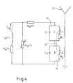
- the coupling of the broadband antenna 5 to the double resonant circuit 13, 14 may alternatively such that the respective input resistance of the antenna 5 parallel to the double resonant circuit 13, 14 ( Figure 2) or in series with the double resonant circuit 13, 14 ( Figure 3) is arranged.
- the coupling may be e.g. inductively (FIG. 4).
- at a serial arrangement of the input resistance of the antenna 5 may be provided that the input resistance only after the oscillation of the double resonant circuit 13, 14th can be switched by means of a switching device 16 ( Figure 5).
- the invention is not limited to the embodiments described above limited.
- to "smooth" the frequency spectrum Also more than two resonant circuits can be used.
- the choice of resonance frequencies the resonant circuits and the nonlinear coupling means, and thus the position and shape of the Frequency spectrum, depends on the particular purpose of the high-performance generator.
- the upper limit of the frequency spectrum is not in the GHz, but in the MHz range lie, so may be on a device to increase the steepness of the pulse generator generated pulse can also be dispensed with.
- the high-performance generator according to the invention can be very compact and is Therefore, especially for installation in bullets for the lethal destruction of electronic However, it can of course also in civilian areas, such as the Space technology.
Landscapes
- Engineering & Computer Science (AREA)
- General Engineering & Computer Science (AREA)
- Physics & Mathematics (AREA)
- Electromagnetism (AREA)
- Radar, Positioning & Navigation (AREA)
- Remote Sensing (AREA)
- Chemical & Material Sciences (AREA)
- Combustion & Propulsion (AREA)
- Magnetic Resonance Imaging Apparatus (AREA)
- Magnetic Treatment Devices (AREA)
- Compressors, Vaccum Pumps And Other Relevant Systems (AREA)
Abstract
Description
- 1
- Hochleistungsgenerator
- 2
- Pulsgenerator
- 3
- elektronische Steuereinrichtung
- 4
- Pulsformer
- 5
- Breitbandantenne, Antenne
- 6
- Sensor
- 7
- Energiequelle
- 8
- Halbleiterkonverter
- 9
- kapazitiver Speicher
- 10
- magnetischer (Spulen-) Flußkompressor, Flußkompressor
- 11
- Öffnungsschalter
- 12
- Entladungseinrichtung
- 13
- erster Parallelschwingkreis
- 14
- zweiter Parallelschwingkreis
- 15
- Kopplungselement, Ferritkern
- 16
- Schaltvorrichtung
- C1
- Kapazität des ersten Schwingkreises
- C2
- Kapazität des zweiten Schwingkreises
- L1
- Induktivität des ersten Schwingkreises
- L2
- Induktivität des zweiten Schwingkreises
- Lg(t)
- Induktivität des Flußkompressors
- R1
- Widerstand der Induktivität des ersten Schwingkreises
- R2
- Widerstand der Induktivität des zweiten Schwingkreises
- Rg(t)
- Widerstand der Induktivität des Flußkompressors
- RM(t)
- Widerstand der Entladungseinrichtung
- Rs(t)
- Widerstand des Öffnungsschalters
Claims (5)
- Hochleistungsgenerator zur Erzeugung eines breitbandigen elektromagnetischen Pulses mit einem einen magnetischen Spulen-Flußkompressor (10) umfassenden Pulsgenerator (2) und einem dem Pulsgenerator (2) nachgeschalteten Pulsformer (4), dadurch gekennzeichnet, daß der Pulsformer (4) eine Schwingkreisanordnung mit mindestens zwei in Serie geschalteten Parallelschwingkreisen (13, 14) unterschiedlicher Resonanzfrequenz umfaßt, wobei die beiden Parallelschwingkreise (13, 14) über mindestens ein nichtlineares ferrimagnetisches Kopplungselement ( 15) miteinander gekoppelt sind.
- Hochleistungsgenerator nach Anspruch 1, dadurch gekennzeichnet, daß es sich bei dem nichtlinearen ferrimagnetischen Kopplungselement (15) um einen rohr- oder stangenförmigen Ferritkern handelt, auf dem die Induktivitäten (L1(t) und L2(t)) der beiden Parallelschwingkreise (13, 14 ) angeordnet sind.
- Hochleistungsgenerator nach Anspruch 2, dadurch gekennzeichnet, daß der Ferritkern (15) eine im wesentlichen rechteckförmige Hystereseschleife aufweist.
- Hochleistungsgenerator nach einem der Ansprüche 1 bis 3, dadurch gekennzeichnet, daß der Pulsgenerator (2) einen dem Spulen-Flußkompressor (10) nachgeschalteten Öffnungsschalter (11) auf der Basis explodierender Drähte umfaßt.
- Hochleistungsgenerator nach Anspruch 4, dadurch gekennzeichnet, daß dem Öffnungsschalter (11) zur Erhöhung der Steilheit der Anstiegsflanke des von dem Öffnungsschalter (11) erzeugten Hochspannungspulses eine Entladungseinrichtung (12) nachgeordnet ist.
Applications Claiming Priority (2)
| Application Number | Priority Date | Filing Date | Title |
|---|---|---|---|
| DE2003142730 DE10342730A1 (de) | 2003-09-16 | 2003-09-16 | Hochleistungsgenerator zur Erzeugung eines breitbandigen elektromagnetischen Pulses |
| DE10342730 | 2003-09-16 |
Publications (2)
| Publication Number | Publication Date |
|---|---|
| EP1517446A2 true EP1517446A2 (de) | 2005-03-23 |
| EP1517446A3 EP1517446A3 (de) | 2006-09-20 |
Family
ID=34177778
Family Applications (1)
| Application Number | Title | Priority Date | Filing Date |
|---|---|---|---|
| EP04018313A Withdrawn EP1517446A3 (de) | 2003-09-16 | 2004-08-03 | Hochleistungsgenerator zur Erzeugung eines breitbandigen elektromagnetischen Pulses |
Country Status (2)
| Country | Link |
|---|---|
| EP (1) | EP1517446A3 (de) |
| DE (1) | DE10342730A1 (de) |
Families Citing this family (1)
| Publication number | Priority date | Publication date | Assignee | Title |
|---|---|---|---|---|
| DE102010024845B4 (de) | 2010-06-23 | 2016-02-18 | Rheinmetall Waffe Munition Gmbh | Hochspannungsgenerator |
Family Cites Families (4)
| Publication number | Priority date | Publication date | Assignee | Title |
|---|---|---|---|---|
| NL208551A (de) * | 1955-07-02 | |||
| GB9424220D0 (en) * | 1994-11-30 | 1995-01-18 | Oxford Instr Limited Rf | Magnetic field pulse generator |
| GB9520357D0 (en) * | 1995-10-05 | 1995-12-06 | Oxford Instr Uk Ltd | Magnetic field pulse generatir |
| DE10044867A1 (de) * | 2000-09-12 | 2002-03-21 | Rheinmetall W & M Gmbh | Explosivstoffgetriebene RF-Strahlenquelle |
-
2003
- 2003-09-16 DE DE2003142730 patent/DE10342730A1/de not_active Withdrawn
-
2004
- 2004-08-03 EP EP04018313A patent/EP1517446A3/de not_active Withdrawn
Also Published As
| Publication number | Publication date |
|---|---|
| EP1517446A3 (de) | 2006-09-20 |
| DE10342730A1 (de) | 2005-04-21 |
Similar Documents
| Publication | Publication Date | Title |
|---|---|---|
| DE3638748C2 (de) | ||
| EP1895653B1 (de) | Verfahren und Einrichtung zum Erzeugen und Abstrahlen eines Hochleistungs-Mikrowellenpulses | |
| DE2437156C2 (de) | Verfahren und Impulsgeneratorschaltung zur Erzeugung von Subnanosekunden-Impulsen | |
| DE102011052096A1 (de) | Verfahren zum Erregen eines HF-Schwingkreises, welcher als Bestandteil einen Zünder zum Zünden eines Brennstoff-Luft-Gemisches in einer Verbrennungskammer hat | |
| EP1699107B1 (de) | 3dB-Koppler | |
| DE10044867A1 (de) | Explosivstoffgetriebene RF-Strahlenquelle | |
| EP2144363B1 (de) | Mikrowellengenerator | |
| DE102013105230A1 (de) | Treiberschaltkreis für einen Transistor | |
| DE2512629C2 (de) | Elektronisch abstimmbares Mikrowellen-Koaxialmagnetron | |
| AT413867B (de) | Kapazitives entladungszündungssystem für einen verbrennungsmotor | |
| EP1769569B1 (de) | Hochspannungsschalter und verwendung desselben bei einem mikrowellengenerator | |
| EP1686684B1 (de) | Mikrowellengenerator | |
| DE1903518B2 (de) | Hochfrequenzoszillator | |
| DE1284479B (de) | Elektrischer Schwingungserzeuger mit mindestens drei von einer Gleichspannungsquelleaufgeladenen Entladekreisen und Schaltmitteln | |
| DE19959358C2 (de) | Autonome RF-Strahlungsquelle | |
| EP1517446A2 (de) | Hochleistungsgenerator zur Erzeugung eines breitbandigen elektromagnetischen Pulses | |
| DE10316120B4 (de) | Mikrowellengenerator | |
| DE19850447B4 (de) | Nicht-linearer Dispersions-Impulsgenerator | |
| DE4401350C1 (de) | Mikrowellen-Impulsgenerator mit Ladungsspeicherdiode | |
| DE69706876T2 (de) | Übertragungsleiter- oder verzögerungsleitungswandler | |
| EP2040374A1 (de) | Mikrowellengenerator | |
| DE102012200634B4 (de) | Leistungskoppler und Schaltschrank mit Leistungskoppler | |
| DE102005044353B4 (de) | Mikrowellengenerator | |
| EP4239884B1 (de) | Marx-generator mit mehreren zweigen für jeweilige marx-spannungen | |
| DE900951C (de) | Sender mit einer von einem synchronisierten Impulsgenerator erregten Magnetronroehre |
Legal Events
| Date | Code | Title | Description |
|---|---|---|---|
| PUAI | Public reference made under article 153(3) epc to a published international application that has entered the european phase |
Free format text: ORIGINAL CODE: 0009012 |
|
| AK | Designated contracting states |
Kind code of ref document: A2 Designated state(s): AT BE BG CH CY CZ DE DK EE ES FI FR GB GR HU IE IT LI LU MC NL PL PT RO SE SI SK TR |
|
| AX | Request for extension of the european patent |
Extension state: AL HR LT LV MK |
|
| RAP1 | Party data changed (applicant data changed or rights of an application transferred) |
Owner name: RHEINMETALL WAFFE MUNITION GMBH |
|
| PUAL | Search report despatched |
Free format text: ORIGINAL CODE: 0009013 |
|
| AK | Designated contracting states |
Kind code of ref document: A3 Designated state(s): AT BE BG CH CY CZ DE DK EE ES FI FR GB GR HU IE IT LI LU MC NL PL PT RO SE SI SK TR |
|
| AX | Request for extension of the european patent |
Extension state: AL HR LT LV MK |
|
| AKX | Designation fees paid | ||
| STAA | Information on the status of an ep patent application or granted ep patent |
Free format text: STATUS: THE APPLICATION IS DEEMED TO BE WITHDRAWN |
|
| 18D | Application deemed to be withdrawn |
Effective date: 20070321 |
|
| REG | Reference to a national code |
Ref country code: DE Ref legal event code: 8566 |