EP1517263A2 - Kombinierter Positions-/Kraftmomentensensor - Google Patents
Kombinierter Positions-/Kraftmomentensensor Download PDFInfo
- Publication number
- EP1517263A2 EP1517263A2 EP04024860A EP04024860A EP1517263A2 EP 1517263 A2 EP1517263 A2 EP 1517263A2 EP 04024860 A EP04024860 A EP 04024860A EP 04024860 A EP04024860 A EP 04024860A EP 1517263 A2 EP1517263 A2 EP 1517263A2
- Authority
- EP
- European Patent Office
- Prior art keywords
- force
- input device
- sensor
- moment
- position sensor
- Prior art date
- Legal status (The legal status is an assumption and is not a legal conclusion. Google has not performed a legal analysis and makes no representation as to the accuracy of the status listed.)
- Withdrawn
Links
Images
Classifications
-
- G—PHYSICS
- G06—COMPUTING OR CALCULATING; COUNTING
- G06F—ELECTRIC DIGITAL DATA PROCESSING
- G06F3/00—Input arrangements for transferring data to be processed into a form capable of being handled by the computer; Output arrangements for transferring data from processing unit to output unit, e.g. interface arrangements
- G06F3/01—Input arrangements or combined input and output arrangements for interaction between user and computer
- G06F3/03—Arrangements for converting the position or the displacement of a member into a coded form
- G06F3/033—Pointing devices displaced or positioned by the user, e.g. mice, trackballs, pens or joysticks; Accessories therefor
- G06F3/0354—Pointing devices displaced or positioned by the user, e.g. mice, trackballs, pens or joysticks; Accessories therefor with detection of two-dimensional [2D] relative movements between the device, or an operating part thereof, and a plane or surface, e.g. 2D mice, trackballs, pens or pucks
- G06F3/03547—Touch pads, in which fingers can move on a surface
-
- G—PHYSICS
- G06—COMPUTING OR CALCULATING; COUNTING
- G06F—ELECTRIC DIGITAL DATA PROCESSING
- G06F3/00—Input arrangements for transferring data to be processed into a form capable of being handled by the computer; Output arrangements for transferring data from processing unit to output unit, e.g. interface arrangements
- G06F3/01—Input arrangements or combined input and output arrangements for interaction between user and computer
- G06F3/03—Arrangements for converting the position or the displacement of a member into a coded form
- G06F3/033—Pointing devices displaced or positioned by the user, e.g. mice, trackballs, pens or joysticks; Accessories therefor
- G06F3/0354—Pointing devices displaced or positioned by the user, e.g. mice, trackballs, pens or joysticks; Accessories therefor with detection of two-dimensional [2D] relative movements between the device, or an operating part thereof, and a plane or surface, e.g. 2D mice, trackballs, pens or pucks
- G06F3/03543—Mice or pucks
-
- G—PHYSICS
- G06—COMPUTING OR CALCULATING; COUNTING
- G06F—ELECTRIC DIGITAL DATA PROCESSING
- G06F3/00—Input arrangements for transferring data to be processed into a form capable of being handled by the computer; Output arrangements for transferring data from processing unit to output unit, e.g. interface arrangements
- G06F3/01—Input arrangements or combined input and output arrangements for interaction between user and computer
- G06F3/03—Arrangements for converting the position or the displacement of a member into a coded form
- G06F3/033—Pointing devices displaced or positioned by the user, e.g. mice, trackballs, pens or joysticks; Accessories therefor
- G06F3/0354—Pointing devices displaced or positioned by the user, e.g. mice, trackballs, pens or joysticks; Accessories therefor with detection of two-dimensional [2D] relative movements between the device, or an operating part thereof, and a plane or surface, e.g. 2D mice, trackballs, pens or pucks
- G06F3/03549—Trackballs
Definitions
- the present invention relates to an input device in which a position sensor combined with a force / moment sensor.
- the general background of the present invention is the driving of real or virtual objects, such as computers, electronic or electrical devices, wherein the drive signals by position sensors or force / moment sensors to be triggered.
- a position sensor is a device that detects the position and / or the Detected relative movement of the device relative to a reference point.
- a force / moment sensor is a device that operates on a control panel of the force / moment sensor detecting and evaluating acting forces and torques.
- Input devices with position sensors the control signals for virtual or real objects depending on the position of the input device and more specifically depends on the Relative movement of the input device relative to a pad or a carrier are known from the prior art. They allow an intuitive and interactive control, for example, of a cursor on a screen surface.
- Examples for Such position input devices are the computer mouse, the touchpad and the Trackball.
- the computer mouse is the most widely used input device. To the basic features of this include the housing with a flat footprint and a structure that allows one-handed operation, one or more buttons on the top, a device for detecting the movement at the bottom as well a cable or an air interface for data transmission to a computer.
- the so-called touchpad is a flat rectangular tray, which touch-sensitive sensors used to determine the location of a device on the Trace tray surface.
- the so-called trackball consists of a ball that is on two rollers is stored. The rollers are arranged at right angles to each other and Transform a movement of the ball into vertical and horizontal movements on the Screen around. He usually has one or more keys to trigger other actions.
- said input devices are well suited for position control.
- a linearly increasing restoring force is missing, the way is no measure for an introduced force.
- forces introduced to the device can not be detected become.
- Even less introduced torques can be detected as a rotation of the input device usually does not lead to any drive signal.
- missing of course a reset torque that returns the input device to a neutral position returns.
- force / moment sensors are known from the prior art, the Output signals with respect to a force / moment vector acting on them and thus Provide output signals with respect to different degrees of freedom. They allow an intuitive Control of real and virtual objects in up to 6 degrees of freedom (eg three translatory and three rotational degrees of freedom). Other degrees of freedom can be achieved by Switch, spin, etc. are provided, the force / torque sensor fixed assigned.
- DE 199 52 560 A1 discloses a method for adjusting and / or adjusting a seat a motor vehicle using a multifunctional, manually operated Input device with force / moment sensor.
- DE 199 52 560 A1 is such Force / moment sensor shown. In that regard, therefore, with respect to the technical details Such a sensor on this figure and the associated description for DE 199 52 Referenced 560 A1.
- the input device has a User interface on which a number of areas for entering at least one Pressure pulses are provided.
- the input device has a device for evaluation and detecting a detected by means of the force / moment sensor and in a force and Moments vector pair converted pressure pulse on. After such selection eg. a to be controlled seat or seat part of a motor vehicle can then selected device linearly by means of an analog signal of the force / torque sensor be controlled.
- the selection of a function and the subsequent activation So are according to this prior art in two temporally separate processes separated.
- the known force / moment sensors an operating part, which, for example, by means of springs with respect to a base part or the like. Is movably mounted in three axes. The range of motion in each axis is usually limited to a few millimeters. In practice it has been shown Therefore, force / moment sensors are poorly suited for position control.
- the object of the present invention is an input device for To propose control of real or virtual objects, the above mentioned Disadvantages avoids.
- This object is achieved according to the invention in that the position and force / moment sensors integrated in one device. This makes it possible, for example, a to approach certain position with the position sensor and then there force and / or Output torque-dependent control signals.
- the input device for controlling virtual and / or Real objects a two-dimensional position sensor and a force / moment sensor on, which acts on a control panel of the force / moment sensor Forces and torques recorded.
- By manual action on the input device are drive signals by the two-dimensional position sensor and / or the force / moment sensor triggered.
- the two-dimensional position sensor built into the input device detects the position of the Input device with respect to the pad by means for detecting the Direction of movement (usually a ball).
- the detection of the situation can take place.
- optical Particularly advantageous is an arcuate configuration of the housing of the Input device.
- the device has two bearing surfaces, with which it rests on a base during operation. In one of these bearing surfaces is the integrated two-dimensional position sensor.
- the control unit of the force-moment sensor is the underside of the arcuate Housing of the input device attached.
- the force / moment sensor is thus only with manipulated the fingertips of the user's hand, causing excessive Load of the force / moment sensor is avoided.
- the user's palm can be comfortable rest on the housing.
- the input device may take the form of a conventional Computer mouse or be round or oval.
- the force / moment sensor is on the Integrated top and the position sensor on the bottom. He can on optical, optomechanical or mechanical way can be realized.
- the force / moment sensor can alternatively be integrated laterally.
- a force / moment sensor can be located at the top or at the side be docked.
- the position sensor and force / moment sensor in this state form a physical unit, the assembled device can be operated with one hand become.
- the two-dimensional position sensor in the top of the control panel of the force torque sensor is integrated.
- the two-dimensional position sensor can be either by a touchpad or be realized by a ball element. If a touchpad is used then by moving the finger on the pad as two-dimensional position information recorded and recycled.
- the ball element trackball is its rotation with respect to the operating part of the force / moment sensor as two-dimensional Position information recorded and utilized.
- the operating part of the force / moment sensor can move freely on the two-dimensional position sensor.
- the two-dimensional position sensor realized by a touchpad.
- the movement of the Keypad of the force / moment sensor on the touchpad are called two-dimensional Position information recorded and utilized.
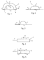
- the housing of the input device 4 in designed essentially arcuate.
- the input device 4 has two Support surfaces 7, 8, with which it rests on a base 6.
- This support surfaces in the case of the support surface 7 shown, is a two-dimensional Position sensor 1 integrated. He records relative movements and thus the location of the Input device 4 with respect to the pad 6. This detection can optically, optomechanically or mechanically.
- the force / moment sensor 2 is at the bottom 9 of the arcuate input device. 4 appropriate. It has a control panel 5, with respect to the housing of the input device. 4 is movably mounted in several axes. Through this special, protected attachment of the operating part 5, it can only be manipulated with the fingertips of the user's hand, whereby a mechanical overload can be avoided in an advantageous manner.
- the Practice has shown that with force / moment sensors there is a risk that they be moved by placing the palm itself to the stop and thus not are more operational.
- the force / moment sensor 2 detects forces and torque effects on the Control panel 5 by means of the relative movement of the control panel 4 in three axes relative to the Housing of the input device 4. While using the input device 4, the Palm of the user conveniently on the top 3 of the housing of the input device 4 rest.
- the drive signals of the position sensor 1 and the force / moment sensor 2 can by means of a cable 11 or an air interface (IR, electromagnetically such as according to FIG Bluetooth standard, etc.) to a computer, electronic or electrical devices be passed on.
- a cable 11 or an air interface IR, electromagnetically such as according to FIG Bluetooth standard, etc.
- the input device 4 has the form of a conventional computer mouse.
- the force / moment sensor 2 is at the top the housing of a conventional computer mouse attached.
- the force / moment sensor 2 is so attached that it can be comfortable with your fingers through Press, pull or turn controls. While using the input device 4 The user's palm can rest comfortably on the housing 3.
- Figure 3 shows a modification of the embodiment of Figure 2 in that the Kradt torque sensor 2 on the front side of the housing of a computer mouse. 3 is arranged, which in turn has the advantage that he in the usual handling of the Computer mouse is manipulated with the fingertips.
- the two-dimensional position sensor 1 is in FIG the operating element 5 of the force / moment sensor 2 integrated.
- the two-dimensional Position sensor 1 can either by a touchpad or as shown by a Trackball 10 can be realized. Be in the control panel 5 of the force / torque sensor thus generating the position drive signals and to the base portion 12 of the force / moment sensor forwarded.
- the two-dimensional one Position sensor 2 by means of a detachable connection, which is schematically indicated by 13, with the force-moment sensor 2 and more precisely with the base part 12 of the force-torque sensor 2 connectable to a physical unit.
Landscapes
- Engineering & Computer Science (AREA)
- General Engineering & Computer Science (AREA)
- Theoretical Computer Science (AREA)
- Human Computer Interaction (AREA)
- Physics & Mathematics (AREA)
- General Physics & Mathematics (AREA)
- Position Input By Displaying (AREA)
- Input From Keyboards Or The Like (AREA)
- Control Of Position Or Direction (AREA)
- Numerical Control (AREA)
Abstract
Description
- mechanisch (hier wird bspw. die Bewegung einer Kugel an der Unterseite in Richtungssignale übersetzt),
- optisch (hier wird die Bewegungserkennung mit Hilfe eines LED - Paares und einer speziellen Mausunterlage mit reflektierendem Gittermuster realisiert) und
- optomechanisch (es werden optische, zwei LED - Paare mit entsprechenden Sensoren, und mechanische Mittel, drehbare Lochscheibe, kombiniert.)
- Fig. 1
- zeigt dabei ein erfindungsgemäßes Eingabegerät, bei dem ein Positionssensor in der Auflagefläche integriert ist und der Kraft/Momentensensor an der Unterseite angebracht ist,
- Fig. 2
- zeigt ein Eingabegerät, das die Form einer herkömmlichen Computermaus hat,
- Fig. 3
- zeigt ein weiteres Eingabegerät, das die Form einer herkömmlichen Computermaus hat,
- Fig. 4
- zeigt ein Eingabegerät, bei dem der Positionssensor in der Oberseite des Bedienteils des Kraft-/Momentensensor integriert ist, und
- Fig. 5
- zeigt eine Anordnung, bei der der Positionssensor mittels einer lösbaren Verbindung mit dem Kraft-/Momentensensor verbindbar ist..
Claims (5)
- Eingabegerät zur Ansteuerung von Computern, elektrischen oder elektronischen Geräten, aufweisend:wobei durch manuelle Manipulation des Eingabegeräts (4) Ansteuersignale durch den 2D-Positionsensor (1) und/oder den Kraft-/Momentensensor (2) auslösbar sind, undeinen 2D-Positionssensor (1), undeinen 3D-Kraft-/Momentensensor (2), der auf ein Bedienteil (4) einwirkende Kräfte und Momente erfasst,
wobei der 2D-Positionssensor (1) und der 3D-Kraft-/Momentensensor (2) an der Oberseite (3) eines Gehäuses des Eingabegeräts angeordnet sind,
diese Oberseite (3) zum Ruhen der Hand des Benutzers auf der Oberseite (3) während der Betätigung des Eingabegeräts (4) ausgebildet ist,
und das Gehäuse zur Auflage auf eine Unterlage (6) ausgebildet ist. - Eingabegerät zur Ansteuerung von Computern, elektrischen oder elektronischen Geräten, aufweisend:wobei durch manuelle Manipulation des Eingabegeräts (4) Ansteuersignale durch den 2D-Positionsensor (1) und/oder den Kraft-/Momentensensor (2) auslösbar sind.einen 2D-Positionssensor (1), undeinen 3D-Kraft-/Momentensensor (2), der auf ein Bedienteil (4) einwirkende Kräfte und Momente erfasst,
- Eingabegerät nach einem der vorhergehenden Ansprüche,
dadurch gekennzeichnet, dass der 3D-Kraft-/Momentensensor (2) Kräfte und Momente zur Erfassung von drei translatorischen und drei rotatorischen Freiheitsgraden ausgebildet ist. - Eingabegerät nach Anspruch 1,
dadurch gekennzeichnet, dass der 2D-Positionssensor (1) eine Relativbewegung gegenüber eines Trägers erfasst. - Eingabegerät nach einem der vorhergehenden Ansprüche,
dadurch gekennzeichnet, dass weitere Freiheitsgrade mittels Schaltern bereitgestellt sind.
Applications Claiming Priority (3)
| Application Number | Priority Date | Filing Date | Title |
|---|---|---|---|
| DE10146473 | 2001-09-21 | ||
| DE10146473A DE10146473A1 (de) | 2001-09-21 | 2001-09-21 | Kombinierter Positions-/Kraftmomentensensor |
| EP02774626A EP1430283A2 (de) | 2001-09-21 | 2002-09-18 | Kombinierter positions-/kraftmomentensensor |
Related Parent Applications (2)
| Application Number | Title | Priority Date | Filing Date |
|---|---|---|---|
| EP02774626.2 Division | 2002-09-18 | ||
| EP02774626A Division EP1430283A2 (de) | 2001-09-21 | 2002-09-18 | Kombinierter positions-/kraftmomentensensor |
Publications (2)
| Publication Number | Publication Date |
|---|---|
| EP1517263A2 true EP1517263A2 (de) | 2005-03-23 |
| EP1517263A3 EP1517263A3 (de) | 2008-01-23 |
Family
ID=7699734
Family Applications (2)
| Application Number | Title | Priority Date | Filing Date |
|---|---|---|---|
| EP02774626A Withdrawn EP1430283A2 (de) | 2001-09-21 | 2002-09-18 | Kombinierter positions-/kraftmomentensensor |
| EP04024860A Withdrawn EP1517263A3 (de) | 2001-09-21 | 2002-09-18 | Kombinierter Positions-/Kraftmomentensensor |
Family Applications Before (1)
| Application Number | Title | Priority Date | Filing Date |
|---|---|---|---|
| EP02774626A Withdrawn EP1430283A2 (de) | 2001-09-21 | 2002-09-18 | Kombinierter positions-/kraftmomentensensor |
Country Status (5)
| Country | Link |
|---|---|
| US (1) | US20040243724A1 (de) |
| EP (2) | EP1430283A2 (de) |
| AU (1) | AU2002340914A1 (de) |
| DE (1) | DE10146473A1 (de) |
| WO (1) | WO2003028003A2 (de) |
Families Citing this family (3)
| Publication number | Priority date | Publication date | Assignee | Title |
|---|---|---|---|---|
| GB0417683D0 (en) * | 2004-08-09 | 2004-09-08 | C13 Ltd | Sensor |
| JP2011503744A (ja) * | 2007-11-15 | 2011-01-27 | エルゴワークス インターナショナル, エルエルシー. | 動力源を有するマウス |
| WO2023014790A1 (en) * | 2021-08-05 | 2023-02-09 | Kokanee Research Llc | Systems with deformable controllers |
Family Cites Families (13)
| Publication number | Priority date | Publication date | Assignee | Title |
|---|---|---|---|---|
| US4811608A (en) * | 1985-12-18 | 1989-03-14 | Spatial Systems Pty Limited | Force and torque converter |
| US5296871A (en) * | 1992-07-27 | 1994-03-22 | Paley W Bradford | Three-dimensional mouse with tactile feedback |
| US5355147A (en) * | 1993-10-04 | 1994-10-11 | Donald Lear | Ergonomic computer mouse |
| DE4400790A1 (de) * | 1993-11-10 | 1995-05-18 | Johannes Dipl Ing Geisen | Vorrichtung und/oder Verfahren zur Kommunikation mit DV-Anlagen bzw. Bedienungsvorrichtungen |
| JP3381344B2 (ja) * | 1993-11-15 | 2003-02-24 | ヤマハ株式会社 | 座標入力装置 |
| US5473344A (en) * | 1994-01-06 | 1995-12-05 | Microsoft Corporation | 3-D cursor positioning device |
| US5751275A (en) * | 1994-11-14 | 1998-05-12 | Bullister; Edward T. | Two-- and three--dimensional trackball with coordinate transformations |
| US5798748A (en) * | 1995-06-07 | 1998-08-25 | Spacetec Imc Corporation | Force and torque converter with improved digital optical sensing circuitry |
| US5771038A (en) * | 1995-08-09 | 1998-06-23 | Primax Electronics Ltd. | Control device for display state change on monitor |
| US5854622A (en) * | 1997-01-17 | 1998-12-29 | Brannon; Daniel J. | Joystick apparatus for measuring handle movement with six degrees of freedom |
| US6707443B2 (en) * | 1998-06-23 | 2004-03-16 | Immersion Corporation | Haptic trackball device |
| JP3909994B2 (ja) * | 2000-02-29 | 2007-04-25 | アルプス電気株式会社 | 入力装置 |
| US6489948B1 (en) * | 2000-04-20 | 2002-12-03 | Benny Chi Wah Lau | Computer mouse having multiple cursor positioning inputs and method of operation |
-
2001
- 2001-09-21 DE DE10146473A patent/DE10146473A1/de not_active Ceased
-
2002
- 2002-09-18 EP EP02774626A patent/EP1430283A2/de not_active Withdrawn
- 2002-09-18 US US10/433,360 patent/US20040243724A1/en not_active Abandoned
- 2002-09-18 WO PCT/EP2002/010473 patent/WO2003028003A2/de not_active Ceased
- 2002-09-18 AU AU2002340914A patent/AU2002340914A1/en not_active Abandoned
- 2002-09-18 EP EP04024860A patent/EP1517263A3/de not_active Withdrawn
Also Published As
| Publication number | Publication date |
|---|---|
| AU2002340914A1 (en) | 2003-04-07 |
| US20040243724A1 (en) | 2004-12-02 |
| WO2003028003A2 (de) | 2003-04-03 |
| EP1430283A2 (de) | 2004-06-23 |
| WO2003028003A3 (de) | 2004-03-25 |
| EP1517263A3 (de) | 2008-01-23 |
| DE10146473A1 (de) | 2003-04-17 |
Similar Documents
| Publication | Publication Date | Title |
|---|---|---|
| EP1513056B1 (de) | 3D-Eingabegerät mit integrierter Anzeigevorrichtung | |
| DE19525644C2 (de) | Vorrichtung zur Eingabe von Daten in einen Computer | |
| DE69018708T2 (de) | Dreidimensionale Maus mit einer Vertiefung. | |
| EP3359348B1 (de) | Robotersystem und verfahren zur steuerung eines robotersystems | |
| DE69122052T2 (de) | Dateneingabegerät für Datenverarbeitungsvorrichtung und Datenverarbeitungsgerät mit derartigem Gerät | |
| DE69622101T2 (de) | 3-d-eingang durch vertikale verschiebung von maus oder rollkugel | |
| DE68918163T2 (de) | Zusammendrückbare Steuervorrichtung für einen Rechner. | |
| DE3883109T2 (de) | Steuerungsgerät. | |
| DE69635902T2 (de) | Verfahren und einrichtung zur kraftrückkopplung für eine graphische benutzerschnittstelle | |
| DE10392966B4 (de) | Parallele haptische Joystick-Vorrichtung | |
| EP3709133B1 (de) | System zur haptischen interaktion mit virtuellen objekten für anwendungen in der virtuellen realität | |
| DE10228185A1 (de) | Einrichtung zur Erfassung einer mechanischen Betätigung eines Eingabeelementes mittels digitaler Technik und Verfahren zur Verarbeitung und Umwandlung des digitalen Eingabesignals in Befehle zur Steuerung eines Verbrauchers | |
| DE102016000353A1 (de) | Kran-, Baumaschinen- oder Flurförderzeug-Simulator | |
| DE20200955U1 (de) | Haptisches Rückkopplungsgerät | |
| DE4400790A1 (de) | Vorrichtung und/oder Verfahren zur Kommunikation mit DV-Anlagen bzw. Bedienungsvorrichtungen | |
| DE112004001937T5 (de) | Haptisches Eingabegerät zur Erzeugung von Steuerungsinformation | |
| DE4211189C2 (de) | 3D-Computermaus | |
| DE10146473A1 (de) | Kombinierter Positions-/Kraftmomentensensor | |
| DE19649573C2 (de) | Eingabegerät zur Übertragung von Bewegungen | |
| DE102009017104B4 (de) | Verfahren und System zur Kraftrückkopplung zum Interagieren mit einer virtualisierten Umgebung | |
| DE20122296U1 (de) | Kombinierter Positions-/Kraftmomentensensor | |
| WO2003042802A2 (de) | Eingabegerät, webcam und bildschirm mit spracheingabefunktion | |
| DE102004048888B4 (de) | Bedieneinrichtung | |
| DE102024113275A1 (de) | Signalausgabemittel für eine Prothese | |
| DE202023001912U1 (de) | Eingabegerät-Manipulator |
Legal Events
| Date | Code | Title | Description |
|---|---|---|---|
| PUAI | Public reference made under article 153(3) epc to a published international application that has entered the european phase |
Free format text: ORIGINAL CODE: 0009012 |
|
| AC | Divisional application: reference to earlier application |
Ref document number: 1430283 Country of ref document: EP Kind code of ref document: P |
|
| AK | Designated contracting states |
Kind code of ref document: A2 Designated state(s): AT BE BG CH CY CZ DE DK EE ES FI FR GB GR IE IT LI LU MC NL PT SE SK TR |
|
| AX | Request for extension of the european patent |
Extension state: AL LT LV MK |
|
| PUAL | Search report despatched |
Free format text: ORIGINAL CODE: 0009013 |
|
| RIC1 | Information provided on ipc code assigned before grant |
Ipc: G06F 3/033 20060101AFI20071204BHEP |
|
| AK | Designated contracting states |
Kind code of ref document: A3 Designated state(s): AT BE BG CH CY CZ DE DK EE ES FI FR GB GR IE IT LI LU MC NL PT SE SK TR |
|
| AX | Request for extension of the european patent |
Extension state: AL LT LV MK |
|
| STAA | Information on the status of an ep patent application or granted ep patent |
Free format text: STATUS: THE APPLICATION IS DEEMED TO BE WITHDRAWN |
|
| AKX | Designation fees paid | ||
| 18D | Application deemed to be withdrawn |
Effective date: 20080401 |
|
| REG | Reference to a national code |
Ref country code: DE Ref legal event code: 8566 |