EP1517160A2 - Diffusion disk - Google Patents
Diffusion disk Download PDFInfo
- Publication number
- EP1517160A2 EP1517160A2 EP04018197A EP04018197A EP1517160A2 EP 1517160 A2 EP1517160 A2 EP 1517160A2 EP 04018197 A EP04018197 A EP 04018197A EP 04018197 A EP04018197 A EP 04018197A EP 1517160 A2 EP1517160 A2 EP 1517160A2
- Authority
- EP
- European Patent Office
- Prior art keywords
- lens according
- facets
- elevations
- coordinates
- vertices
- Prior art date
- Legal status (The legal status is an assumption and is not a legal conclusion. Google has not performed a legal analysis and makes no representation as to the accuracy of the status listed.)
- Withdrawn
Links
- 238000009792 diffusion process Methods 0.000 title 1
- 238000000342 Monte Carlo simulation Methods 0.000 claims description 5
- 239000006185 dispersion Substances 0.000 abstract description 3
- 230000000694 effects Effects 0.000 description 5
- 230000009466 transformation Effects 0.000 description 5
- 230000008859 change Effects 0.000 description 4
- 239000000463 material Substances 0.000 description 4
- 238000002845 discoloration Methods 0.000 description 3
- 230000006978 adaptation Effects 0.000 description 2
- 230000008901 benefit Effects 0.000 description 2
- 230000001419 dependent effect Effects 0.000 description 2
- 238000000034 method Methods 0.000 description 2
- 230000008569 process Effects 0.000 description 2
- 230000015572 biosynthetic process Effects 0.000 description 1
- 238000011161 development Methods 0.000 description 1
- 230000018109 developmental process Effects 0.000 description 1
- 239000013013 elastic material Substances 0.000 description 1
- 239000011521 glass Substances 0.000 description 1
- 238000005286 illumination Methods 0.000 description 1
- 238000007654 immersion Methods 0.000 description 1
- 230000002093 peripheral effect Effects 0.000 description 1
- 230000009467 reduction Effects 0.000 description 1
- 230000007480 spreading Effects 0.000 description 1
Images


Classifications
-
- G—PHYSICS
- G02—OPTICS
- G02B—OPTICAL ELEMENTS, SYSTEMS OR APPARATUS
- G02B5/00—Optical elements other than lenses
- G02B5/02—Diffusing elements; Afocal elements
- G02B5/0205—Diffusing elements; Afocal elements characterised by the diffusing properties
- G02B5/021—Diffusing elements; Afocal elements characterised by the diffusing properties the diffusion taking place at the element's surface, e.g. by means of surface roughening or microprismatic structures
- G02B5/0215—Diffusing elements; Afocal elements characterised by the diffusing properties the diffusion taking place at the element's surface, e.g. by means of surface roughening or microprismatic structures the surface having a regular structure
-
- F—MECHANICAL ENGINEERING; LIGHTING; HEATING; WEAPONS; BLASTING
- F21—LIGHTING
- F21V—FUNCTIONAL FEATURES OR DETAILS OF LIGHTING DEVICES OR SYSTEMS THEREOF; STRUCTURAL COMBINATIONS OF LIGHTING DEVICES WITH OTHER ARTICLES, NOT OTHERWISE PROVIDED FOR
- F21V5/00—Refractors for light sources
- F21V5/04—Refractors for light sources of lens shape
-
- G—PHYSICS
- G02—OPTICS
- G02B—OPTICAL ELEMENTS, SYSTEMS OR APPARATUS
- G02B5/00—Optical elements other than lenses
- G02B5/02—Diffusing elements; Afocal elements
- G02B5/0273—Diffusing elements; Afocal elements characterized by the use
- G02B5/0278—Diffusing elements; Afocal elements characterized by the use used in transmission
Definitions
- a discharge lamp is selected as the illumination means, then so Occur in the peripheral area of the light field discoloration, which depending on the discharge lamp type may have different color.
- the invention is based on the technical problem, a To provide a diffuser, which is a uniformly round light field generated. Furthermore, the lens is a light field with specifiable Provide gradients of illuminance, i. H. the light field should select soft or hard to the edge.
- the new approach is to move away from to deviate from the regular arrangement of the facets. This happens by providing a lens that is a transparent base body having a first surface, wherein the first surface is subdivided into facets, and at each facet a survey or depression with a second, arched trained surface is assigned to the facets assume different geometric shapes.
- a facet within the meaning of the invention is intended to mean a surface be that of the edge contour of the respective geometric shape is spanned.
- a flat or arched surface can be the facet, which by the geometric Formed forms, also be flat or curved.
- the elevation or depression associated with the facet ceases Element of the lens.
- the survey or depression has the Facet as a base and is located at least substantially above or below this base.
- the survey or Deepening acts as a lens in the lighting case.
- the solution according to the invention results in a superposition a variety of differently contoured light fields and thus as desired to a round light field.
- facets associated elevations or depressions can be a light field with provide a selectable gradient of illuminance, or such that the specifiable soft or hard leaking.
- a soft light field is one with a small one Gradients of illuminance toward the edge of the light field. Conversely, a strong gradient of illuminance leads to the edge of the light field to a hard-going light field.
- Another advantage obtained is that with the new Facet configuration marginal discoloration when using Discharge lamps are avoided.
- the facets a polygonal Have edge contour.
- the number of corners of the polygons is variable.
- the polygonal edge contour facets should be the surface completely cover, otherwise there is no local scattering effect is. This could possibly be the desire for a uniform Irregularity.
- lenses can be provided, in which the facets have different surface areas.
- Polygons can be three, four, five, six and / or seven corners to get voted.
- the links between adjacent ones Corners of polygons can be straight or curved lines.
- the vault can be spherical, and the survey or depression accordingly be formed dome-shaped. Alternatively, the curvature aspherical.
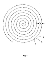
- a first solution variant provided a lens, the one transparent base body having a first surface, wherein the first surface is subdivided into facets, and at each facet a survey or depression with a second, arched trained surface is assigned, and in which the Vertices S of the elevations or depressions along a Spiral are arranged.
- the vertex S of the survey or depression is defined as Intersection of passing through the facet centroid Surface normal of the facet with the curved surface of the facet Survey or immersion.
- the base material of the lens preferably glass, is in one Forming process processed. This is the viscous, hot Base material introduced into the mold. That fills under pressure Base material from the cavity of the mold and forms the Geometry of the mold as a negative starting. The forming process lasts until the base material has cooled and has and without Deformation can be removed from the mold.
- the molds needed to make the lenses, the optionally provided with elevations and / or depressions, are made using radius cutters on CNC-controlled machine tools produced.
- the facets are aimed at the surface of the Cover the diffuser completely.
- the surface indicates of the mold a nationwide arrangement of Depressions on each of which has a polygonal edge contour feature.
- curved base body be provided for the lens.
- a correspondingly curved surface of the To choose mold So can the main body, and this according to the mold, be spherically curved. In this Case would be the cutter with its axis of rotation parallel to Align the radius vector of the dome.
- the height of the surveys or depressions can over the Spreading disc can be varied away, so that the surveys and Recesses vary in height or depth. This also contributes towards the goal, a round and more or less soft or hard To provide expiring light field.
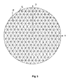
- the vertices S are on an Archimedean spiral, cf. Fig. 1.
- the center (0, 0) of the coordinate system is the starting point inside the spiral.
- the arc length L between two adjacent points S 1 and S 2 is then at a distance of the spiral turns.
- the individual points S 1 , S 2 ... are obtained by continued removal of the constant arc length L along the spiral from inside to outside.
- the vertices may be arranged equidistant from each other.
- a variable arc length L possible. So can one from the inside out increasing arc length L can be selected.
- the facets become larger, the Height of the elevations or the depth of the wells is larger and the scattering effect is also greater.
- the light field then has a rather small half - beam angle with quite high illuminance in the Center on. In contrast, at constant L, the Illuminance rather plateau-shaped and soft leaking.
- the aforementioned measures allow, in a variety of ways, the diffuser to the respective lighting system, for example the respective reflector to adapt.
- the diffuser to the respective lighting system for example the respective reflector to adapt.
- the value of the arc length L but also by variation or constancy of the arc length an adaptation to a reflector respectively.
- These measures allow the light field in to influence given areas of the lighting system, to strengthen or weaken it locally, thus allowing for varied way to optimize the light field.
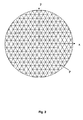
- a lens which has a transparent base body with a first surface, wherein the first surface is divided into facets, and in which each facet is associated with a protrusion or depression with a second, curved surface formed, and in the the vertices of the elevations and / or depressions are characterized in that their coordinates (x s , y s ) from the coordinates ( x P , y P ) of all points P, which form an array of facets with regular hexagonal edge contour, by rotation by an angle ⁇ around a center (0,0).
- the first equation stands for a set of horizontally aligned lines.
- the second equation describes a set of positive slope straight lines of tan 60 °, and the third equation describes a set of negative slope tan lines of 120 °.
- intersections P which are shown in FIG.
- the intersections lying in a plane have the coordinates ( x P , y P ) with x as horizontal and y as vertical axis.
- x P , y P the coordinates
- x the coordinates
- y P the coordinates
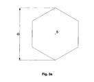
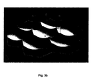
- Fig. 3a shows such a facet with diagonal D in a plan view.
- Fig. 3b shows this according to a section of a Diffuser with curved recesses with apex S. Zu Each recess has a hexagonal edge contour.
- Equation system 2 where N, X ', Y', R 'and ⁇ ' represent mathematical intermediate variables.
- the output coordinates ( x P , y P ) are thus transformed to final coordinates ( x P ', y P ').
- each point P undergoes a shift by a certain arc length L. With the distance of the points P from the center (0,0) this takes Arc length too. It may increase linearly as seen in Figure 4, or the increase may be with a root or exponential function.
- the set of all points ( x P ', y P ') is in the sense of the above statements in a plane. This requires a flat body. If desired, however, a curved body can be provided. In this case, the set of all points ( x P ', y P ') must still be mapped onto the curved surface in an appropriate way.
- S and P are different with respect to the z-coordinates, with the z-axis being perpendicular to the drawing plane of FIG.
- the difference in the z-coordinate represents the height of the elevation or the depth of the recess.
- , can be chosen variably.
- the angle ⁇ for the Transformation is not constant but increases with increasing Distance from the center to. In this respect, too large ⁇ am Diffuser edge can be avoided as desired, and this at sufficient scattering effect inside the lens.
- a lens which has a transparent base body with a first surface, wherein the first surface is subdivided into facets, and wherein each facet is associated with a protrusion or depression with a second, curved surface formed, and in the the vertices S of the elevations or depressions are characterized in that their coordinates ( x S ", y S "), the coordinates ( x P , y P ) of all points P, which form an array of facets with regular hexagonal edge contour, by random variation using the Monte Carlo method.
- FIG. 5 shows, on the one hand, the points of intersection P of an arrangement of facets with a regular hexagonal edge contour according to system of equations 1 with the coordinates ( x P , y P ) as in FIG. 2, supplemented by the points S obtained via the Monte Carlo method Coordinates ( x S ", y S ") which represent the vertices of the elevations or depressions.
- the parameters U and V are in the range of approximately 5%. to about 20% of the facet diagonals D. Be U or V even larger chosen, so there is an increasing danger that the body has gaps between the facets.
- Fig. 6 shows a facet arrangement similar to EP 0 961 136 A1.
- the diffuser has a diameter of 138 mm and is covered with facets with a regular hexagonal edge contour. Each hexagon has a diagonal D of 10 mm.
- Each bump is spherically curved with a radius of curvature of 10 mm.
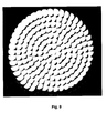
- Fig. 9 shows a lens with a diameter of 138 mm, in which the Vertices are arranged on an Archimedean spiral.
- the Output facet was regularly contoured hexagonal as in Fig. 6, however with a diagonal D of 12 mm.
- the spiral spacing d is 9 mm, and the arc length L is also 9 mm.
- Any spherical arched Elevation has a radius of curvature of 10 mm.
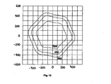
- the isolux distribution shows values of constant illuminance of 1000, 500 and 200 lux.
- the values of constant illuminance take a hexagonal Shape, i. the light field is overall pronounced hexagonal.
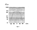
- Fig. 11 shows a so-called horizontal for the same lamp Illuminance distribution, ie the course of the illuminance along the horizontally oriented x-axis as in EP 0 961 136 A2.
- the illuminance has a central plateau-shaped Area on, and a sharp-edged garbage towards the edge.
- Fig. 12 shows the light field of the same lamp as in Fig. 10, however with a diffuser according to the invention.
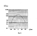
- FIG. 13 shows in a representation corresponding to FIG. 11 Result, when the lamp with a lens according to the invention Is provided.
- the course of the illuminance is bell-shaped, the slope change is slow, the light field is soft discontinued.
Landscapes
- Physics & Mathematics (AREA)
- General Physics & Mathematics (AREA)
- Optics & Photonics (AREA)
- Engineering & Computer Science (AREA)
- General Engineering & Computer Science (AREA)
- Optical Elements Other Than Lenses (AREA)
- Moulds For Moulding Plastics Or The Like (AREA)
Abstract
Description
Wird zudem als Beleuchtungsmittel eine Entladungslampe gewählt, so treten im randseitigen Bereich des Lichtfelds Verfärbungen auf, welche je nach Entladungslampentyp unterschiedliche Farbe haben können.If, in addition, a discharge lamp is selected as the illumination means, then so Occur in the peripheral area of the light field discoloration, which depending on the discharge lamp type may have different color.
Der Erfindung liegt das technische Problem zugrunde, eine Streuscheibe bereitzustellen, welche ein gleichmäßig rundes Lichtfeld erzeugt. Weiterhin soll die Streuscheibe ein Lichtfeld mit vorgebbarem Gradienten der Beleuchtungsstärke bereitstellen, d. h. das Lichtfeld soll zum Rand hin wählbar weich oder hart auslaufen.The invention is based on the technical problem, a To provide a diffuser, which is a uniformly round light field generated. Furthermore, the lens is a light field with specifiable Provide gradients of illuminance, i. H. the light field should select soft or hard to the edge.
Die Lösung dieses technischen Problems erfolgt durch die Merkmale der unabhängigen Ansprüche. Vorteilhafte Weiterbildungen werden durch die abhängigen Ansprüche angegeben.The solution to this technical problem is provided by the features the independent claims. Advantageous developments are indicated by the dependent claims.
Erfindungsgemäß wurde erkannt, dass die zentrale Ursache für das
nicht runde Lichtfeld bei der Streuscheibe gemäß EP 0 961 136 A2 die
regelmäßige Anordnung der Facetten ist. Die Regelmäßigkeit der
Facetten artikuliert sich hierbei in der gleichen Form, Größe, und
Orientierung der Facetten. Da das mit der Streuscheibe auf eine Fläche
gerichtete Licht letztlich eine Superposition der sechseckigen
Lichtfelder der einzelnen Facetten ist, wird das Lichtfeld der EP 0 961
136 A2 insofern selbst sechseckig.According to the invention, it has been recognized that the central cause of the
not round light field in the diffuser according to
Aufbauend auf dieser Erkenntnis besteht der neue Ansatz darin, von der regelmäßigen Anordnung der Facetten abzuweichen. Dies geschieht dadurch, dass eine Streuscheibe bereitgestellt wird, die einen transparenten Grundkörper mit einer ersten Oberfläche aufweist, wobei die erste Oberfläche in Facetten unterteilt ist, und bei der jeder Facette eine Erhebung oder Vertiefung mit einer zweiten, gewölbt ausgebildeten Oberfläche zugeordnet ist, wobei die Facetten unterschiedliche geometrische Formen annehmen. Building on this insight, the new approach is to move away from to deviate from the regular arrangement of the facets. This happens by providing a lens that is a transparent base body having a first surface, wherein the first surface is subdivided into facets, and at each facet a survey or depression with a second, arched trained surface is assigned to the facets assume different geometric shapes.
Unter einer Facette im Sinne der Erfindung soll eine Fläche verstanden werden, die von der Randkontur der jeweiligen geometrischen Form aufgespannt wird. Je nach Ausbildung der ersten Oberfläche, d.h. der Oberfläche des Grundkörpers der Streuscheibe, als ebene oder gewölbte Fläche kann die Facette, welche durch die geometrischen Formen aufgespannt wird, ebenfalls eben oder gewölbt sein.A facet within the meaning of the invention is intended to mean a surface be that of the edge contour of the respective geometric shape is spanned. Depending on the formation of the first surface, i. of the Surface of the body of the lens, as a flat or arched surface can be the facet, which by the geometric Formed forms, also be flat or curved.
Die der Facette zugeordneten Erhebung oder Vertiefung stellt ein Element der Streuscheibe dar. Die Erhebung oder Vertiefung besitzt die Facette als Grundfläche und befindet sich zumindest im wesentlichen oberhalb oder unterhalb dieser Grundfläche. Die Erhebung oder Vertiefung wirkt im Beleuchtungsfall als Linse.The elevation or depression associated with the facet ceases Element of the lens. The survey or depression has the Facet as a base and is located at least substantially above or below this base. The survey or Deepening acts as a lens in the lighting case.
Durch die erfindungsgemäße Lösung kommt es zu einer Superposition einer Vielzahl unterschiedlich konturierter Lichtfelder und damit wunschgemäß zu einem runden Lichtfeld. Abhängig von der jeweiligen Facettenkonfiguration und der Beschaffenheit der den Facetten zugeordneten Erhebungen oder Vertiefungen lässt sich ein Lichtfeld mit einem wählbar Gradienten der Beleuchtungsstärke bereitstellen, bzw. ein solches das vorgebbar weich oder hart ausläuft.The solution according to the invention results in a superposition a variety of differently contoured light fields and thus as desired to a round light field. Depending on the particular Facet configuration and the nature of the facets associated elevations or depressions can be a light field with provide a selectable gradient of illuminance, or such that the specifiable soft or hard leaking.
Ein weich auslaufendes Lichtfeld ist ein solches mit einem geringen Gradienten der Beleuchtungsstärke zum Rand des Lichtfeldes hin. Umgekehrt führt ein starker Gradient der Beleuchtungsstärke am Rand des Lichtfeldes zu einem hart auslaufenden Lichtfeld.A soft light field is one with a small one Gradients of illuminance toward the edge of the light field. Conversely, a strong gradient of illuminance leads to the edge of the light field to a hard-going light field.
Ein weiterer erzielter Vorteil besteht darin, dass mit der neuen Facettenkonfiguration randseitige Verfärbungen beim Einsatz von Entladungslampen vermieden werden.Another advantage obtained is that with the new Facet configuration marginal discoloration when using Discharge lamps are avoided.
Um die Unterschiedlichkeit der einzelnen zur Superposition beitragenden Lichtfelder zu erhöhen und darüber die oben genannten Vorteile zu erzielen, können verschiedene Maßnahmen ergriffen werden.To the difference of the individual to the superposition to increase contributing light fields and above the above To achieve advantages, various measures can be taken become.
So kann vorgesehen sein, dass die Facetten eine polygonale Randkontur aufweisen. Hierbei ist die Eckenzahl der Polygone variabel. Die Facetten mit polygonaler Randkontur sollten die Oberfläche vollständig bedecken, da ansonsten lokal keine Streuwirkung gegeben ist. Dies könnte ggf. dem Wunsch nach einer gleichmäßigen Ausleuchtung zuwiderlaufen.So it can be provided that the facets a polygonal Have edge contour. Here, the number of corners of the polygons is variable. The polygonal edge contour facets should be the surface completely cover, otherwise there is no local scattering effect is. This could possibly be the desire for a uniform Irregularity.
Weiterhin können auch Streuscheiben bereitgestellt werden, bei denen die Facetten unterschiedliche Flächeninhalte aufweisen.Furthermore, lenses can be provided, in which the facets have different surface areas.
Als Polygone können Drei-, Vier-, Fünf-, Sechs- und/oder Sieben-Ecke gewählt werden. Die Verbindungsstrecken zwischen benachbarten Ecken der Polygone können gerade oder gebogene Linien sein.Polygons can be three, four, five, six and / or seven corners to get voted. The links between adjacent ones Corners of polygons can be straight or curved lines.
Als weitere Folge der Unregelmäßigkeit der Facetten ergibt sich, dass diese unterschiedliche Orientierungen aufweisen.Another consequence of the irregularity of the facets is that have these different orientations.
Eine weitere Maßnahme, mit der man sich dem Ziel runder Lichtfelder, und hinsichtlich der Beleuchtungsstärke zum Rand hin weich oder hart auslaufender Lichtfelder nähert, ist die Wahl und ggf. Variation der jeweiligen Wölbung der Erhebungen oder Vertiefungen. Die Wölbung kann sphärisch sein, und die Erhebung bzw. Vertiefung entsprechend kalottenförmig ausgebildet sein. Alternativ kann die Wölbung asphärisch gewählt werden.Another measure aimed at achieving the goal of round light fields, and in terms of illuminance, soft or hard towards the edge approaching light fields is the choice and possibly variation of respective curvature of the elevations or depressions. The vault can be spherical, and the survey or depression accordingly be formed dome-shaped. Alternatively, the curvature aspherical.
Weiterhin besteht zur Gewährleistung des o.g. Ziels die Möglichkeit, die Tiefe der Ausnehmungen bzw. die Höhe der Erhebungen zu variieren. Furthermore, to ensure the o.g. Goal the possibility of Depth of the recesses or the height of the surveys to vary.
Aus den vorstehenden Ausführungen ergibt sich, dass die aufgeführten Maßnahmen alternativ oder kumulativ vorgesehen werden können.From the above it follows that the listed Measures may be provided alternatively or cumulatively.
Zur praktischen Umsetzung der vorstehend genannten Lösung ist in einer ersten Lösungsvariante eine Streuscheibe vorgesehen, die einen transparenten Grundkörper mit einer ersten Oberfläche aufweist, wobei die erste Oberfläche in Facetten unterteilt ist, und bei der jeder Facette eine Erhebung oder Vertiefung mit einer zweiten, gewölbt ausgebildeten Oberfläche zugeordnet ist, und bei dem die Scheitelpunkte S der Erhebungen oder Vertiefungen entlang einer Spirale angeordnet sind.For practical implementation of the above solution is in a first solution variant provided a lens, the one transparent base body having a first surface, wherein the first surface is subdivided into facets, and at each facet a survey or depression with a second, arched trained surface is assigned, and in which the Vertices S of the elevations or depressions along a Spiral are arranged.
Der Scheitelpunkt S der Erhebung oder Vertiefung sei definiert als Schnittpunkt der durch den Facettenschwerpunkt hindurchtretenden Oberflächennormale der Facette mit der gewölbten Oberfläche der Erhebung oder Vertiefung.The vertex S of the survey or depression is defined as Intersection of passing through the facet centroid Surface normal of the facet with the curved surface of the facet Survey or immersion.
Nachfolgend soll beispielhaft eine Möglichkeit näher erläutert werden, wie eine derartige Streuscheibe gefertigt werden kann.Below, by way of example, a possibility will be explained in more detail, how such a lens can be made.
Das Grundmaterial der Streuscheibe, vorzugsweise Glas, wird in einem Umformprozess verarbeitet. Dabei wird das zähflüssige, heiße Grundmaterial in das Formwerkzeug eingeführt. Unter Druck füllt das Grundmaterial den Hohlraum des Formwerkzeuges aus und bildet die Geometrie des Formwerkzeuges als Negativ ab. Der Umformprozess dauert solange, bis das Grundmaterial sich abgekühlt und hat und ohne Deformation aus dem Formwerkzeug entnommen werden kann.The base material of the lens, preferably glass, is in one Forming process processed. This is the viscous, hot Base material introduced into the mold. That fills under pressure Base material from the cavity of the mold and forms the Geometry of the mold as a negative starting. The forming process lasts until the base material has cooled and has and without Deformation can be removed from the mold.
Die zur Anfertigung der Streuscheiben benötigten Formwerkzeuge, die wahlweise mit Erhöhungen und/oder Vertiefungen versehen sind, werden mittels Radiusfräser auf CNC-gesteuerten Werkzeugmaschinen hergestellt. The molds needed to make the lenses, the optionally provided with elevations and / or depressions, are made using radius cutters on CNC-controlled machine tools produced.
Werden in das Formwerkzeug zwei Vertiefungen hinreichend dicht nebeneinander eingebracht, so verbleibt beim Einsatz eines Kugelfräsers ein stegförmiger Rand zwischen den beiden Vertiefungen. Sind die benachbarten Vertiefungen gleich tief, und weisen sie den gleichen Radius auf, so ist ihr gemeinsamer Rand in einer Aufsicht linear. Besitzt eine Vertiefung sechs angrenzende Vertiefungen als Nachbarn, so kann sich für diese Vertiefung eine Berandung ergeben, die aus insgesamt sechs linearen stegförmigen Rändern besteht. In einer Aufsicht besitzt diese Vertiefung somit eine regelmäßige sechseckige Randkontur. Abhängig von der genauen Lage und der Zahl der benachbarten Vertiefungen ergibt sich im allgemeinen Fall eine Vertiefung mit einer polygonalen Randkontur.Be in the mold two wells sufficiently tight placed side by side, so remains when using a Ball mill a web-shaped edge between the two wells. Are the adjacent wells the same depth, and they have the same radius, so is their common edge in a plan linear. Has a well six adjacent wells as Neighbors, it may result in a boundary for this depression, which consists of a total of six linear web-shaped edges. In a supervision has this depression thus a regular hexagonal edge contour. Depending on the exact location and the Number of adjacent pits results in the general case a recess with a polygonal edge contour.
Sind bei zwei benachbarten Vertiefungen der Radius und/oder die Tiefe der Ausfräsung unterschiedlich, so ist im allgemeinen der gemeinsame Rand gekrümmt, und es ergeben sich für die Vertiefungen Ränder die in einer Aufsicht unterschiedliche geometrische Formen annehmen.Are at two adjacent wells of the radius and / or Depth of the cutout different, so is in general the common edge curved, and it emerge for the depressions The edges in a plan different geometric shapes accept.
Im Regelfall wird angestrebt, dass die Facetten die Oberfläche der Streuscheibe vollständig bedecken. In diesem Fall weist die Oberfläche des Formwerkzeugs eine flächendeckende Anordnung von Vertiefungen auf welche jeweils über eine polygonale Randkontur verfügen.As a rule, the facets are aimed at the surface of the Cover the diffuser completely. In this case, the surface indicates of the mold a nationwide arrangement of Depressions on each of which has a polygonal edge contour feature.
Selbstverständlich können aus ästhetischen oder technischen Gründen auch gewölbte Grundkörper für die Streuscheibe vorgesehen sein. In diesem Fall ist eine entsprechend gewölbte Oberfläche des Formwerkzeugs zu wählen. So kann der Grundkörper, und hierzu entsprechend das Formwerkzeug, sphärisch gewölbt sein. In diesem Fall wäre der Fräser mit seiner Rotationsachse parallel zum Radiusvektor der Kalotte auszurichten. Of course, for aesthetic or technical reasons also curved base body be provided for the lens. In In this case, a correspondingly curved surface of the To choose mold. So can the main body, and this according to the mold, be spherically curved. In this Case would be the cutter with its axis of rotation parallel to Align the radius vector of the dome.
Durch die Anordnung der Scheitelpunkte S entlang einer Spirale entsteht eine Vielzahl von unregelmäßig angeordneten Facetten, mit welchen wunschgemäß ein rundes Lichtfeld geschaffen wird, welches bei Entladungslampen im Randbereich keine Verfärbungen aufweist, und dessen Gradient der Beleuchtungsstärke vorgegeben werden kann.By arranging the vertices S along a spiral creates a variety of irregularly arranged facets, with which wishfully a round light field is created, which has no discoloration in discharge lamps in the edge region, and whose gradient of illuminance can be specified can.
Die Höhe der Erhebungen bzw. Vertiefungen kann über die Streuscheibe hinweg variiert werden, so dass die Erhebungen und Vertiefungen unterschiedlich hoch bzw. tief ausfallen. Auch dies trägt zum Ziel bei, ein rundes und mehr oder weniger weich oder hart auslaufendes Lichtfeld bereitzustellen.The height of the surveys or depressions can over the Spreading disc can be varied away, so that the surveys and Recesses vary in height or depth. This also contributes towards the goal, a round and more or less soft or hard To provide expiring light field.
In einer Ausgestaltung der Streuscheibe befinden sich die
Scheitelpunkte S auf einer Archimedischen Spirale, vgl. Fig. 1. Die
Gleichung dieser Spirale in Polarkoordinaten (r, ϕ) lautet
Das Zentrum (0, 0) des Koordinatensystems ist hierbei der im Inneren
der Spirale befindliche Startpunkt. Die Bogenlänge L zwischen zwei
benachbarten Punkte S1 und S2 ist dann bei einem Abstand der
Spiralenwindungen.
![]()
![]()
Die einzelnen Punkte S1, S2 ... erhält man durch fortgesetztes Abtragen der konstanten Bogenlänge L längs der Spirale von innen nach außen.The individual points S 1 , S 2 ... are obtained by continued removal of the constant arc length L along the spiral from inside to outside.
Die Scheitelpunkte können äquidistant zueinander angeordnet sein. Neben der äquidistanten Anordnung der Scheitelpunkte ist auch eine variable Bogenlänge L möglich. So kann eine von innen nach außen zunehmende Bogenlänge L gewählt werden. Auf diese Weise erhält man im Inneren der Streuscheibe kleine Facetten mit Erhebungen geringer Höhe bzw. mit Vertiefungen geringer Tiefe, und somit eine kleine Streuwirkung. Zum Rand hin werden die Facetten größer, die Höhe der Erhebungen bzw. die Tiefe der Vertiefungen wird größer und die Streuwirkung wird ebenfalls größer. Das Lichtfeld weist dann einen eher kleinen Halbstreuwinkel mit recht großer Beleuchtungsstärke im Zentrum auf. Im Gegensatz hierzu wäre bei konstantem L die Beleuchtungsstärke eher plateauförmig und weich auslaufend.The vertices may be arranged equidistant from each other. In addition to the equidistant arrangement of the vertices is also a variable arc length L possible. So can one from the inside out increasing arc length L can be selected. In this way receives inside the diffuser small facets with elevations low altitude or with depressions of shallow depth, and thus a small scattering effect. To the edge, the facets become larger, the Height of the elevations or the depth of the wells is larger and the scattering effect is also greater. The light field then has a rather small half - beam angle with quite high illuminance in the Center on. In contrast, at constant L, the Illuminance rather plateau-shaped and soft leaking.
Die vorstehend genannten Maßnahmen, welche alternativ und ggf. kumulativ ergriffen werden können, erlauben es, auf vielfältige Weise, die Streuscheibe an das jeweilige Beleuchtungssystem, zum Beispiel den jeweiligen Reflektor, anzupassen. So kann durch die Wahl des Spiralentyps, des Werts der Bogenlänge L, aber auch durch Variation oder Konstanz der Bogenlänge eine Anpassung an einen Reflektor erfolgen. Diese Maßnahmen ermöglichen es, das Lichtfeld in vorgegebenen Bereichen des Beleuchtungssystems zu beeinflussen, es lokal zu verstärken oder zu schwächen, und erlauben somit auf vielfältige Weise, das Lichtfeld zu optimieren.The aforementioned measures, which alternatively and possibly cumulatively, allow, in a variety of ways, the diffuser to the respective lighting system, for example the respective reflector to adapt. Thus, by choosing the Spiral type, the value of the arc length L, but also by variation or constancy of the arc length an adaptation to a reflector respectively. These measures allow the light field in to influence given areas of the lighting system, to strengthen or weaken it locally, thus allowing for varied way to optimize the light field.
In einer zweiten Lösungsvariante, vgl. Fig. 4, ist eine Streuscheibe vorgesehen, die einen transparenten Grundkörper mit einer ersten Oberfläche aufweist, wobei die erste Oberfläche in Facetten unterteilt ist, und bei der jeder Facette eine Erhebung oder Vertiefung mit einer zweiten, gewölbt ausgebildeten Oberfläche zugeordnet ist, und bei der die Scheitelpunkte der Erhebungen und/oder Vertiefungen dadurch charakterisiert sind, dass sich ihre Koordinaten (xs, ys) aus den Koordinaten (xP , yP ) aller Punkte P, welche eine Anordnung von Facetten mit regelmäßiger sechseckiger Randkontur bilden, durch Verdrehung um einen Winkel δ um ein Zentrum (0,0) ergeben. In a second solution variant, cf. 4, a lens is provided, which has a transparent base body with a first surface, wherein the first surface is divided into facets, and in which each facet is associated with a protrusion or depression with a second, curved surface formed, and in the the vertices of the elevations and / or depressions are characterized in that their coordinates (x s , y s ) from the coordinates ( x P , y P ) of all points P, which form an array of facets with regular hexagonal edge contour, by rotation by an angle δ around a center (0,0).
Zur Erläuterung dieser Lösung sei zunächst dargestellt, wie eine
Anordnung von Facetten mit regelmäßiger sechseckiger Randkontur
mathematisch beschreibbar ist. Die Anordnung kann dargestellt werden
aus drei Systemen jeweils zueinander gleichabständiger Linien, wobei
jedes System gegenüber dem Nachbarsystem um 60° verdreht ist, und
deren Linien durch die nachfolgenden Gleichungen beschrieben
werden:
Hierbei ist D die Facettendiagonale. Diese drei Gleichungen mögen
nachfolgend als das Gleichungssystem 1 bezeichnet werden. Die erste
Gleichung steht für einen Satz von horizontal ausgerichteten Linien. Die
zweite Gleichung beschreibt einen Satz von Geraden mit positiver
Steigung von tan 60°, und die dritte Gleichung einen Satz von Geraden
mit negativer Steigung von tan 120°. i ist ein Index mit
Diese drei Liniensysteme bilden Schnittpunkte P, die in der Fig. 2 dargestellt sind. Die Schnittpunkte, welche in einer Ebene liegen, haben hierbei die Koordinaten (xP , yP ) mit x als horizontale und y als vertikale Achse. An jeden Punkt P grenzen in Fig. 2 sechs Dreiecke, die gemeinsam eine Facette bilden welche eine regelmäßige sechseckige Randkontur aufweist. These three line systems form intersections P, which are shown in FIG. The intersections lying in a plane have the coordinates ( x P , y P ) with x as horizontal and y as vertical axis. At each point P in FIG. 2, six triangles bound together, which together form a facet which has a regular hexagonal edge contour.
Fig. 3a zeigt eine derartige Facette mit Diagonale D in einer Aufsicht. Fig. 3b zeigt hierzu entsprechend einen Ausschnitt aus einer Streuscheibe mit gewölbten Ausnehmungen mit Scheitelpunkt S. Zu jeder Ausnehmung gehört eine sechseckige Randkontur.Fig. 3a shows such a facet with diagonal D in a plan view. Fig. 3b shows this according to a section of a Diffuser with curved recesses with apex S. Zu Each recess has a hexagonal edge contour.
Bezeichnet man die Koordinaten eines derartigen Schnittpunktes P mit
(xP ,yP ) unter Heranziehung kartesischer Koordinaten bzw. (r, ϕ) bei
Heranziehung von Polarkoordinaten, so kann eine Verdrehung dadurch
erfolgen, dass folgende Transformation durchgeführt wird:

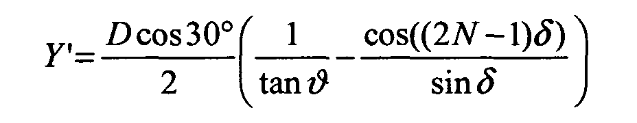
Diese neun Gleichungen mögen nachfolgend als das Gleichungssystem 2 bezeichnet werden, wobei N, X', Y', R' und ϕ' rechnerische Zwischengrößen darstellen.These nine equations are below like that Equation system 2, where N, X ', Y', R 'and φ' represent mathematical intermediate variables.
Die Ausgangskoordinaten (xP , yP ) werden somit auf Endkoordinaten (xP ', yP ') transformiert. Das mathematische Ergebnis kann man sich anschaulich dadurch vorstellen, als hätte man eine Streuscheibe aus einem elastischen Material, welche um einen Winkel δ tordiert wird. Dies zeigt Fig. 4, bei der die durchgezogenen Linien durch den Mittelpunkt die Tordierung veranschaulichen. Für den Grenzfall δ=0° liegt wieder eine Anordnung von Facetten mit regelmäßiger sechseckiger Randkontur vor. Die Tordierung bewirkt im inneren Bereich eine kleinere Veränderung der Ausgangskoordinaten, und im Außenbereich eine große Veränderung. Es sei hervorgehoben, dass die Tordierung lediglich einer Veranschaulichung der mathematischen Transformation darstellt, und nicht wörtlich zu nehmen ist.The output coordinates ( x P , y P ) are thus transformed to final coordinates ( x P ', y P '). The mathematical result can be visualized as if one had a diffuser of an elastic material, which is twisted by an angle δ. This is shown in Fig. 4, in which the solid lines through the center illustrate the twisting. For the limiting case δ = 0 ° there is again an arrangement of facets with a regular hexagonal edge contour. The twisting causes a smaller change of the initial coordinates in the inner area, and a great change in the outer area. It should be emphasized that the ordinance is merely an illustration of the mathematical transformation, and is not to be taken literally.
Bei der Transformation der Ausgangskoordinaten (xP , yP ) in Endkoordinaten (xP ', yP ') erfährt jeder Punkt P eine Verschiebung um eine gewissen Bogenlänge L. Mit dem Abstand der Punkte P vom Zentrum (0,0) nimmt diese Bogenlänge zu. Sie kann linear zunehmen wie in Fig. 4 ersichtlich, oder die Zunahme kann mit einer Wurzel- oder Exponentialfunktion erfolgen.In the transformation of the initial coordinates ( x P , y P ) into final coordinates ( x P ', y P '), each point P undergoes a shift by a certain arc length L. With the distance of the points P from the center (0,0) this takes Arc length too. It may increase linearly as seen in Figure 4, or the increase may be with a root or exponential function.
Die Menge aller Punkte (xP ', yP ') befindet sich im Sinne der vorstehenden Ausführungen in einer Ebene. Dies setzt einen ebenen Grundkörper voraus. Sofern gewünscht kann jedoch auch ein gewölbter Grundkörper vorgesehen werden. In diesem Fall muss die Menge aller Punkte (xP ', yP ') noch auf geeignete Weise auf die gewölbte Fläche abgebildet werden.The set of all points ( x P ', y P ') is in the sense of the above statements in a plane. This requires a flat body. If desired, however, a curved body can be provided. In this case, the set of all points ( x P ', y P ') must still be mapped onto the curved surface in an appropriate way.
Die x- und y-Koordinaten eines Punktes P und des zugehörigen Scheitelpunktes S sind identisch, d. h. x S ' = xP' und yS' = yP'. S und P unterscheiden sich bezüglich der z-Koordinaten, wobei die z-Achse senkrecht auf der Zeichenebene von Fig. 2 steht. Der Unterschied in der z-Koordinate repräsentiert die Höhe der Erhebung bzw. die Tiefe der Ausnehmung. Im einfachsten Fall unterscheiden sich die z-Koordinaten um einen festen Wert, so dass zS'=zP'+const. Allerdings kann, wie oben aufgeführt, die Höhe der Erhebungen bzw. die Tiefe der Erhebungen, und damit |zS ' - zP '| , variabel gewählt werden.The x and y coordinates of a point P and the associated vertex S are identical, ie x S ' = x P ' and y S '= y P ' . S and P are different with respect to the z-coordinates, with the z-axis being perpendicular to the drawing plane of FIG. The difference in the z-coordinate represents the height of the elevation or the depth of the recess. In the simplest case, the z-coordinates differ by a fixed value, so that z S '= z P ' + const . However, as stated above, the height of the surveys or the depth of the surveys, and thus | z S '- z P ' | , can be chosen variably.
Die Auswirkungen, die ein gewählter Transformations- bzw. Tordierungswinkel δ auf das sich ergebende Facettenbild hat, ist dabei von dem Verhältnis des Streuscheibendurchmessers zu der Facettendiagonalen D abhängig. Wird der Tordierungswinkel zu groß gewählt, so ist das Ergebnis eine nahezu glatte Fläche am Streuscheibenrand und damit eine verschwindende Streuung in diesen Bereichen. Insofern führt ein kleinerer Winkel δ zu einer weniger glatten Fläche im Außenbereich und zu besserer Streuung am Rand. Andererseits führt eine Verkleinderung von δ naturgemäß zu einer nur sehr geringen Veränderung in der regelmäßigen Anordnung der Facetten und damit zunehmend zu den vorgenannten Nachteilen einer regelmäßigen Facettenanordnung.The effects that a chosen transformation or Tordierungswinkel δ has on the resulting facet image is doing from the ratio of the diffuser diameter to the Facet diagonal D dependent. Will the twist angle become too big chosen, the result is an almost smooth surface on Diffuser edge and thus a vanishing dispersion in these Areas. In this respect, a smaller angle δ leads to a less smooth Surface in the outer area and for better dispersion at the edge. On the other hand, a reduction of δ naturally leads to only one very little change in the regular arrangement of the Facets and thus increasingly to the aforementioned disadvantages of a regular facet arrangement.
In einer vorteilhaften Weiterbildung ist der Winkel δ für die Transformation nicht konstant, sondern nimmt mit zunehmendem Abstand vom Zentrum zu. Insofern kann ein zu großes δ am Streuscheibenrand wunschgemäß vermieden werden, und dies bei ausreichender Streuwirkung im Inneren der Streuscheibe.In an advantageous embodiment, the angle δ for the Transformation is not constant but increases with increasing Distance from the center to. In this respect, too large δ am Diffuser edge can be avoided as desired, and this at sufficient scattering effect inside the lens.
In einer dritten Lösungsvariante, vgl. Fig. 5, ist eine Streuscheibe vorgesehen, die einen transparenten Grundkörper mit einer ersten Oberfläche aufweist, wobei die erste Oberfläche in Facetten unterteilt ist, und bei dem jeder Facette eine Erhebung oder Vertiefung mit einer zweiten, gewölbt ausgebildeten Oberfläche zugeordnet ist, und bei der die Scheitelpunkte S der Erhebungen oder Vertiefungen dadurch charakterisiert sind, dass sich ihre Koordinaten (xS ", yS "), aus den Koordinaten (xP , yP ) aller Punkte P, welche eine Anordnung von Facetten mit regelmäßiger sechseckiger Randkontur bilden, durch Zufallsvariierung mit Hilfe des Monte-Carlo-Verfahrens hervorgehen.In a third solution variant, cf. 5, a lens is provided, which has a transparent base body with a first surface, wherein the first surface is subdivided into facets, and wherein each facet is associated with a protrusion or depression with a second, curved surface formed, and in the the vertices S of the elevations or depressions are characterized in that their coordinates ( x S ", y S "), the coordinates ( x P , y P ) of all points P, which form an array of facets with regular hexagonal edge contour, by random variation using the Monte Carlo method.
Die hierzu eingesetzten Zufallszahlen Z werden mit Hilfe des Monte-Carlo-Verfahrens
im Bereich 0 ≤ Z < 1 variiert, wobei
Die Punkte P (xP , yP , zP ) und S (xS ", yS ", zS ") unterscheiden sich wie bei der zweiten Lösungsvariante in der z-Koordinate, wobei |zS "-zP | die Höhe der Erhebung bzw. die Tiefe der Ausnehmung repräsentiert.The points P ( x P , y P , z P ) and S ( x S ", y S ", z S ") differ in the z-coordinate as in the second solution variant, where | z S " - z P | represents the height of the survey or the depth of the recess.
Fig. 5 zeigt zum einen die Schnittpunkte P einer Anordnung von
Facetten mit regelmäßiger sechseckiger Randkontur gemäß
Gleichungssystem 1 mit den Koordinaten (xP , yP ) wie in Fig. 2, ergänzt
um die über das Monte-Carlo-Verfahren erhaltenen Punkte S mit
Koordinaten (xS ", yS ") welche die Scheitelpunkte der Erhebungen bzw.
Vertiefungen darstellen.5 shows, on the one hand, the points of intersection P of an arrangement of facets with a regular hexagonal edge contour according to system of
Vorteilhafterweise liegen die Parameter U und V im Bereich von ca. 5% bis ca. 20% der Facettendiagonalen D. Werden U bzw. V noch größer gewählt, so besteht zunehmend die Gefahr, dass der Grundkörper zwischen den Facetten Lücken aufweist.Advantageously, the parameters U and V are in the range of approximately 5%. to about 20% of the facet diagonals D. Be U or V even larger chosen, so there is an increasing danger that the body has gaps between the facets.
Aus den vorstehenden Ausführungen ergibt sich, dass dem Fachmann mit den Lösungsvarianten eine Fülle von Parametern an die Hand gegeben wird, wie er das Lichtfeld unter Berücksichtigung des Beleuchtungssystems gestalten und anpassen kann. Insofern erlaubt der gewählte Ansatz der unterschiedlichen geometrischen Formen für die Facetten eine sehr vielfältige und variable Anpassung des Lichtfeldes an die jeweiligen Verhältnisse. Es tritt hinzu, dass zur Realisierung eines wunschgemäßen Lichtfeldes auch mehrere Möglichkeiten offen stehen, die sich im Design unterscheiden. Insofern erlauben es die Lösungsvarianten auch, hinsichtlich des ästhetischen Erscheinungsbildes optimierte Streuscheiben bereitzustellen.From the above statements it follows that the person skilled in the art with the solution variants a wealth of parameters at hand given as he takes the light field in consideration of the Design and customize lighting system. Insofar allowed the chosen approach of different geometric shapes for the facets a very diverse and variable adaptation of the Light field to the respective conditions. It also adds that to Realization of a desired light field also several Possibilities are open, which differ in the design. insofar It also allows the solution variants, in terms of aesthetic Appearance optimized lenses to provide.
Nachfolgend soll die Erfindung anhand von Ausführungsbeispielen näher erläutert werden.The invention is based on embodiments be explained in more detail.
Fig. 6 zeigt eine Facettenanordnung ähnlich wie in der EP 0 961 136
A1. Die Streuscheibe hat einen Durchmesser von 138 mm und ist
flächendeckend mit Facetten mit regelmäßiger sechseckiger
Randkontur belegt. Jedes Sechseck hat eine Diagonale D von 10 mm.
Zur Modellierung wurde das Gleichungssystem 1 mit iA=9 und iE=9
herangezogen. Jede Erhebung ist sphärisch gekrümmt, wobei der
Krümmungsradius 10 mm beträgt.Fig. 6 shows a facet arrangement similar to
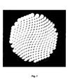
Fig. 7 zeigt in einer Aufsicht eine Ausführungsform, bei der die regelmäßige Anordnung gemäß Fig. 6 im Sinne der zweiten Lösungsvariante mit Hilfe des Gleichungssystems 2 um δ = 3° verdreht bzw. tordiert wurde. Man erkennt, dass die Facetten nunmehr unregelmäßig angeordnet sind. Die Facetten weisen nicht mehr alle die gleiche Form, sondern unterschiedliche Flächeninhalte und eine unterschiedliche Zahl von Ecken auf. Auch die Orientierungen der Facetten sind unterschiedlich.Fig. 7 shows in a plan view an embodiment in which the regular arrangement of FIG. 6 in the sense of the second Solution variant with the help of the equation system 2 twisted by δ = 3 ° or was twisted. It can be seen that the facets are now are arranged irregularly. The facets are no longer all that same shape, but different surface areas and one different number of corners. Also the orientations of the Facets are different.
Fig. 8 zeigt ein Beispiel, bei der die Koordinaten der regelmäßigen Facettenanordnung gemäß Fig. 6 mittels des Monte-Carlo-Verfahrens zufallsvariiert wurde. Es war U=0,2 * D und V=0,2 * D. Mit D=10 mm ergibt sich damit U=V=2 mm. Auch hier sind die Facetten unterschiedlich konturiert und orientiert, und weichen optisch deutlich sichtbar von der regelmäßigen Anordnung gemäß Fig. 6 ab. Fig. 8 shows an example in which the coordinates of the regular Facet arrangement according to FIG. 6 by means of the Monte Carlo method was randomly varied. It was U = 0.2 * D and V = 0.2 * D. With D = 10 mm this results in U = V = 2 mm. Again, the facets are differently contoured and oriented, and give way visually visible from the regular arrangement of FIG. 6 from.
Fig. 9 zeigt eine Streuscheibe mit Durchmesser 138 mm, bei der die Scheitelpunkte auf einer Archimedischen Spirale angeordnet sind. Die Ausgangsfacette war regelmäßig sechseckig konturiert wie in Fig. 6, jedoch mit einer Diagonale D von 12 mm. Der Spiralenabstand d ist 9 mm, und die Bogenlänge L ist ebenfalls 9 mm. Jede sphärisch gewölbte Erhebung hat einen Krümmungsradius von 10 mm.Fig. 9 shows a lens with a diameter of 138 mm, in which the Vertices are arranged on an Archimedean spiral. The Output facet was regularly contoured hexagonal as in Fig. 6, however with a diagonal D of 12 mm. The spiral spacing d is 9 mm, and the arc length L is also 9 mm. Any spherical arched Elevation has a radius of curvature of 10 mm.
Fig. 10 zeigt eine so genannte Isoluxverteilung der xy-Ebene des
Lichtfeldes, mit x als horizontaler und y als vertikaler Achse, für den Fall
einer Leuchte mit einer Streuscheibe, deren Oberfläche mit einer
regelmäßigen Facettenanordnung nach dem Gleichungssystem 1
ausgestattet ist, wie im Fall der EP 0 961 136 A2. Die Isoluxverteilung
zeigt Werte konstanter Beleuchtungsstärke von 1000, 500 und 200 Lux.
Die Werte konstanter Beleuchtungsstärke nehmen eine sechseckige
Form an, d.h. das Lichtfeld ist insgesamt ausgeprägt sechseckig.10 shows a so-called isolux distribution of the xy plane of the
Light field, with x as horizontal and y as a vertical axis, in case
a lamp with a diffuser, the surface of which with a
regular facet arrangement according to the
Fig. 11 zeigt für die gleiche Leuchte eine so genannte horizontale
Beleuchtungsstärkeverteilung, also den Verlauf der Beleuchtungsstärke
längs der horizontal ausgerichteten x-Achse wie bei der EP 0 961 136
A2. Die Beleuchtungsstärke weist einen zentralen plateauförmigen
Bereich auf, und einen scharfkantigen Abfall zum Rand hin.Fig. 11 shows a so-called horizontal for the same lamp
Illuminance distribution, ie the course of the illuminance
along the horizontally oriented x-axis as in
Fig. 12 zeigt das Lichtfeld der gleichen Leuchte wie bei Fig. 10, jedoch mit einer erfindungsgemäßen Streuscheibe. Die Linien konstanter Beleuchtungsstärke sind rund, das Lichtfeld in seiner Gesamtheit ebenfalls.Fig. 12 shows the light field of the same lamp as in Fig. 10, however with a diffuser according to the invention. The lines more constant Illuminance is round, the light field in its entirety also.
Fig. 13 zeigt in einer zu Fig. 11 korrespondierenden Darstellung das Ergebnis, wenn die Leuchte mit einer erfindungsgemäßen Streuscheibe ausgestattet ist. Der Verlauf der Beleuchtungsstärke ist glockenförmig, die Steigungsänderung erfolgt langsam, das Lichtfeld ist insofern weich auslaufend.FIG. 13 shows in a representation corresponding to FIG. 11 Result, when the lamp with a lens according to the invention Is provided. The course of the illuminance is bell-shaped, the slope change is slow, the light field is soft discontinued.
Claims (18)
dadurch gekennzeichnet, dass die Facetten unterschiedliche geometrische Formen annehmen.Lens having a transparent base body (1) with a first surface (2), wherein the first surface (2) is divided into facets (3), and in which each facet (3) has a protrusion or depression (4) with a second, curved surface (5) is associated,
characterized in that the facets assume different geometric shapes.
dadurch gekennzeichnet, dass die Facetten eine polygonale Randkontur aufweisen.Lens according to claim 1,
characterized in that the facets have a polygonal edge contour.
dadurch gekennzeichnet, dass die Facetten unterschiedliche Flächeninhalte aufweisen.Lens according to claim 2,
characterized in that the facets have different surface areas.
dadurch gekennzeichnet, dass die Facetten die Form eines Drei-, Vier-, Fünf-, Sechs- und/oder Sieben-Ecks annehmen.Lens according to claim 2 or 3,
characterized in that the facets take the form of a three, four, five, six and / or seven-corner.
dadurch gekennzeichnet, dass die Facetten unterschiedliche Orientierungen aufweisen.Lens according to one of claims 1 to 4,
characterized in that the facets have different orientations.
dadurch gekennzeichnet, dass die Erhebungen oder Vertiefungen (4) kalottenförmig ausgebildet sind.Lens according to one of claims 1 to 5,
characterized in that the elevations or depressions (4) are formed dome-shaped.
dadurch gekennzeichnet, dass die Höhe der Erhebungen und/oder die Tiefe der Vertiefungen unterschiedlich gewählt sind.Lens according to one of claims 1 to 6,
characterized in that the height of the elevations and / or the depth of the recesses are chosen differently.
dadurch gekennzeichnet, dass die jeweiligen Scheitelpunkte (S) der Erhebungen oder Vertiefungen entlang einer Spirale angeordnet sind.Lens according to the preamble of claim 1,
characterized in that the respective vertices (S) of the elevations or depressions are arranged along a spiral.
dadurch gekennzeichnet, dass die Scheitelpunkte (S) auf einer Archimedischen Spirale angeordnet sind.Lens according to claim 8,
characterized in that the vertices (S) are arranged on an Archimedean spiral.
dadurch gekennzeichnet, dass die Bogenlänge (L) zwischen zwei benachbarten Scheitelpunkten (S) entlang der Spirale nahezu äquidistant ist.Lens according to claim 8 or 9,
characterized in that the arc length (L) between two adjacent vertices (S) along the spiral is nearly equidistant.
dadurch gekennzeichnet, dass die Bogenlänge (L) zwischen zwei benachbarten Scheitelpunkten (S) entlang der Spirale variabel gestaltet ist.Lens according to claim 8 or 9,
characterized in that the arc length (L) between two adjacent vertices (S) along the spiral is made variable.
dadurch gekennzeichnet, dass die Höhe der Erhebungen und/oder die Tiefe der Vertiefungen unterschiedlich gewählt sind. Lens according to one of claims 8 to 11,
characterized in that the height of the elevations and / or the depth of the recesses are chosen differently.
dadurch gekennzeichnet, dass die Scheitelpunkte (S) der Erhebungen und/oder Vertiefungen (4) dadurch charakterisiert sind, dass sich ihre Koordinaten (xS ', yS ') aus den Koordinaten (xP , yP ) aller Punkte (P), welche eine Anordnung von Facetten mit regelmäßiger sechseckiger Randkontur definieren, durch Verdrehung um einen Winkel δ um ein Zentrum (0,0) ergeben.Lens according to the preamble of claim 1,
characterized in that the vertices (S) of the elevations and / or depressions (4) are characterized in that their coordinates ( x S ', y S ') from the coordinates ( x P , y P ) of all points (P) , which define an array of facets with a regular hexagonal edge contour, by twisting at an angle δ around a center (0,0).
dadurch gekennzeichnet, dass der Winkel δ mit zunehmendem Abstand vom Zentrum zunimmt.Lens according to claim 13,
characterized in that the angle δ increases with increasing distance from the center.
dadurch gekennzeichnet, dass der Winkel δ linear oder mit einer Wurzel- oder Exponentialfunktion zunimmt.Lens according to claim 14,
characterized in that the angle δ increases linearly or with a root or exponential function.
dadurch gekennzeichnet, dass die Höhe der Erhebungen und/oder die Tiefe der Vertiefungen unterschiedlich sind.Lens according to one of claims 13 to 15,
characterized in that the height of the elevations and / or the depth of the recesses are different.
dadurch gekennzeichnet, dass die Scheitelpunkte (S) der Erhebungen oder Vertiefungen dadurch charakterisiert sind, dass sich ihre Koordinaten (xS ", yS "), aus den Koordinaten (xP , yP ) aller Punkte (P), welche eine Anordnung von Facetten mit regelmäßiger sechseckiger Randkontur definieren, durch Zufallsvariierung mit Hilfe des Monte-Carlo-Verfahrens hervorgehen.Lens according to the preamble of claim 1,
characterized in that the vertices (S) of the elevations or depressions are characterized in that their coordinates ( x S ", y S "), from the coordinates ( x P , y P ) of all points (P), which is an arrangement define facets with a regular hexagonal edge contour, emerge by random variation using the Monte Carlo method.
dadurch gekennzeichnet, dass die Höhe der Erhebungen und/oder die Tiefe
der Vertiefungen unterschiedlich sind.Lens according to claim 16,
characterized in that the height of the elevations and / or the depth
the wells are different.
Applications Claiming Priority (2)
| Application Number | Priority Date | Filing Date | Title |
|---|---|---|---|
| DE10343630 | 2003-09-20 | ||
| DE10343630A DE10343630B4 (en) | 2003-09-20 | 2003-09-20 | diffuser |
Publications (2)
| Publication Number | Publication Date |
|---|---|
| EP1517160A2 true EP1517160A2 (en) | 2005-03-23 |
| EP1517160A3 EP1517160A3 (en) | 2005-04-13 |
Family
ID=34177861
Family Applications (1)
| Application Number | Title | Priority Date | Filing Date |
|---|---|---|---|
| EP04018197A Withdrawn EP1517160A3 (en) | 2003-09-20 | 2004-07-31 | Diffusion disk |
Country Status (5)
| Country | Link |
|---|---|
| US (2) | US7443588B2 (en) |
| EP (1) | EP1517160A3 (en) |
| JP (1) | JP4326438B2 (en) |
| CN (2) | CN100529803C (en) |
| DE (1) | DE10343630B4 (en) |
Cited By (2)
| Publication number | Priority date | Publication date | Assignee | Title |
|---|---|---|---|---|
| EP2284577A3 (en) * | 2007-11-23 | 2011-08-24 | OSRAM Opto Semiconductors GmbH | Optical construction component and lighting device |
| DE102019102329A1 (en) * | 2019-01-30 | 2020-07-30 | Automotive Lighting Reutlingen Gmbh | Optical disk for a lighting device |
Families Citing this family (16)
| Publication number | Priority date | Publication date | Assignee | Title |
|---|---|---|---|---|
| DE10343630B4 (en) * | 2003-09-20 | 2007-11-15 | Schott Ag | diffuser |
| US7583444B1 (en) | 2005-12-21 | 2009-09-01 | 3M Innovative Properties Company | Process for making microlens arrays and masterforms |
| JP2009537870A (en) * | 2006-05-18 | 2009-10-29 | スリーエム イノベイティブ プロパティズ カンパニー | Method for manufacturing light guide with extraction structure and light guide manufactured by the method |
| JP4935513B2 (en) * | 2007-06-06 | 2012-05-23 | ソニー株式会社 | OPTICAL ELEMENT AND ITS MANUFACTURING METHOD, OPTICAL ELEMENT MANUFACTURING REPLICATION BOARD AND ITS MANUFACTURING METHOD |
| DE102008023551B4 (en) | 2008-05-14 | 2019-05-09 | Automotive Lighting Reutlingen Gmbh | Lighting device in the form of a projection headlight for motor vehicles |
| IL196690A0 (en) * | 2008-05-29 | 2011-08-01 | Plasan Sasa Ltd | Interchangeable door |
| DE102008060969A1 (en) * | 2008-12-08 | 2010-06-10 | Osram Gesellschaft mit beschränkter Haftung | diffuser |
| JP5510865B2 (en) * | 2009-03-25 | 2014-06-04 | 住友化学株式会社 | Anti-glare treatment method, anti-glare film manufacturing method and mold manufacturing method |
| EP3097442A1 (en) * | 2014-01-23 | 2016-11-30 | Philips Lighting Holding B.V. | Light diffuser, led lamp arrangement using the same, and manufacturing method |
| US20150307033A1 (en) * | 2014-04-29 | 2015-10-29 | Global Ip Holdings, Llc | Vehicle trim part having a layered, decorative finish and configured to form a light pattern at the front of the part |
| CN103926639B (en) * | 2014-04-30 | 2016-08-31 | 张家港康得新光电材料有限公司 | A kind of brightness enhancement film and preparation method thereof and comprise the backlight module of this brightness enhancement film |
| JP6390194B2 (en) * | 2014-06-18 | 2018-09-19 | オムロン株式会社 | Optical element and surface light source device |
| CN109154682B (en) * | 2016-05-19 | 2021-03-26 | 昕诺飞控股有限公司 | Optical output device and design method |
| CN109398220A (en) * | 2017-08-18 | 2019-03-01 | 深圳市绎立锐光科技开发有限公司 | Headlight regulating device and system |
| DE102018131556A1 (en) | 2018-12-10 | 2020-06-10 | HELLA GmbH & Co. KGaA | Method for producing an optical component, optical component and lighting device for a motor vehicle |
| CN113251382A (en) * | 2021-05-11 | 2021-08-13 | 深圳市照耀科技有限公司 | Bead surface and lens using same |
Citations (3)
| Publication number | Priority date | Publication date | Assignee | Title |
|---|---|---|---|---|
| US4823246A (en) * | 1986-12-23 | 1989-04-18 | Cibie Projecteurs | Shallow indicator light for a motor vehicle |
| EP0961136A2 (en) | 1998-05-28 | 1999-12-01 | CLAY PAKY S.p.A. | Optical diffuser and lighting device equipped therewith |
| US6086227A (en) * | 1998-09-11 | 2000-07-11 | Osram Sylvania Inc. | Lamp with faceted reflector and spiral lens |
Family Cites Families (20)
| Publication number | Priority date | Publication date | Assignee | Title |
|---|---|---|---|---|
| JPS57139927U (en) * | 1981-02-27 | 1982-09-01 | ||
| JPS61142648A (en) | 1984-12-14 | 1986-06-30 | Hitachi Ltd | Sample stage for scanning electron microscope |
| JP2566417B2 (en) * | 1987-08-05 | 1996-12-25 | 旭光学工業株式会社 | Focusing screen |
| US5042911A (en) * | 1989-03-08 | 1991-08-27 | Gte Products Corporation | Method of making lighting lens |
| US5124839A (en) * | 1989-11-08 | 1992-06-23 | Canon Kabushiki Kaisha | Phase-type focusing screen |
| US5119235A (en) * | 1989-12-21 | 1992-06-02 | Nikon Corporation | Focusing screen and method of manufacturing same |
| US5177637A (en) * | 1990-09-11 | 1993-01-05 | Nikon Corporation | Focusing screen including different height microlenses arranged in a cyclical pattern |
| US5247390A (en) * | 1991-11-05 | 1993-09-21 | Aharon Zeev Hed | Lightweight low-loss refractive light diffusion system |
| US5965327A (en) * | 1991-12-03 | 1999-10-12 | Asahi Kogaku Kogyo Kaisha | Method for manufacturing a master die for a diffusion plate and diffusion manufactured by said method |
| JPH06102415A (en) * | 1992-09-24 | 1994-04-15 | Keiwa Shoko Kk | Condenser plate |
| CA2108959A1 (en) * | 1992-11-16 | 1994-05-17 | Thomas M. Golz | Lenticular lens |
| US5442252A (en) * | 1992-11-16 | 1995-08-15 | General Electric Company | Lenticulated lens with improved light distribution |
| US5995303A (en) * | 1994-09-30 | 1999-11-30 | Kabushiki Kaisha Toshiba | Optical element and optical device |
| US5580164A (en) * | 1995-03-07 | 1996-12-03 | High End Systems, Inc. | Power lens for an automated luminaire |
| US6079854A (en) * | 1998-02-13 | 2000-06-27 | Ra; Dojin | Device and method for diffusing light |
| US6822794B2 (en) * | 2000-12-15 | 2004-11-23 | Agilent Technologies, Inc. | Diffractive optical element for providing favorable multi-mode fiber launch and reflection management |
| CN2462424Y (en) * | 2001-01-12 | 2001-11-28 | 唐世杰 | Diffusing lens |
| US6778148B1 (en) * | 2002-12-04 | 2004-08-17 | The United States Of America As Represented By The Secretary Of The Navy | Sensor array for enhanced directivity |
| DE10343630B4 (en) * | 2003-09-20 | 2007-11-15 | Schott Ag | diffuser |
| DE10361121A1 (en) * | 2003-12-22 | 2005-07-21 | Schott Ag | Optical arrangement with stepped lens |
-
2003
- 2003-09-20 DE DE10343630A patent/DE10343630B4/en not_active Expired - Fee Related
-
2004
- 2004-07-31 EP EP04018197A patent/EP1517160A3/en not_active Withdrawn
- 2004-09-13 JP JP2004265175A patent/JP4326438B2/en not_active Expired - Fee Related
- 2004-09-16 US US10/943,120 patent/US7443588B2/en not_active Expired - Fee Related
- 2004-09-20 CN CNB2004100798111A patent/CN100529803C/en not_active Expired - Fee Related
- 2004-09-20 CN CN2009101594434A patent/CN101725893B/en not_active Expired - Fee Related
-
2008
- 2008-09-19 US US12/233,851 patent/US7729054B2/en not_active Expired - Fee Related
Patent Citations (3)
| Publication number | Priority date | Publication date | Assignee | Title |
|---|---|---|---|---|
| US4823246A (en) * | 1986-12-23 | 1989-04-18 | Cibie Projecteurs | Shallow indicator light for a motor vehicle |
| EP0961136A2 (en) | 1998-05-28 | 1999-12-01 | CLAY PAKY S.p.A. | Optical diffuser and lighting device equipped therewith |
| US6086227A (en) * | 1998-09-11 | 2000-07-11 | Osram Sylvania Inc. | Lamp with faceted reflector and spiral lens |
Cited By (3)
| Publication number | Priority date | Publication date | Assignee | Title |
|---|---|---|---|---|
| EP2284577A3 (en) * | 2007-11-23 | 2011-08-24 | OSRAM Opto Semiconductors GmbH | Optical construction component and lighting device |
| US8757849B2 (en) | 2007-11-23 | 2014-06-24 | Osram Gesellschaft Mit Beschrankter Haftung | Optical component and illumination device |
| DE102019102329A1 (en) * | 2019-01-30 | 2020-07-30 | Automotive Lighting Reutlingen Gmbh | Optical disk for a lighting device |
Also Published As
| Publication number | Publication date |
|---|---|
| JP2005092205A (en) | 2005-04-07 |
| DE10343630A1 (en) | 2005-05-25 |
| HK1073684A1 (en) | 2005-10-14 |
| CN1598398A (en) | 2005-03-23 |
| US20050063064A1 (en) | 2005-03-24 |
| HK1144164A1 (en) | 2011-01-28 |
| DE10343630B4 (en) | 2007-11-15 |
| US7443588B2 (en) | 2008-10-28 |
| US7729054B2 (en) | 2010-06-01 |
| US20090015925A1 (en) | 2009-01-15 |
| CN101725893B (en) | 2013-10-23 |
| CN101725893A (en) | 2010-06-09 |
| EP1517160A3 (en) | 2005-04-13 |
| JP4326438B2 (en) | 2009-09-09 |
| CN100529803C (en) | 2009-08-19 |
Similar Documents
| Publication | Publication Date | Title |
|---|---|---|
| EP1517160A2 (en) | Diffusion disk | |
| DE60212598T2 (en) | PRISMATIC RETROREFLECTOR WITH A MULTIPLANAR FACETTE | |
| DE69915174T2 (en) | Module for controlling the divergence and shape of the beam for projected light | |
| DE10254499B4 (en) | Layer arrangement with a lens-like effect generating diffractive optical effective structure | |
| DE1497626B1 (en) | Cornea contact lens trial set and cornea contact lenses | |
| DE202009018881U1 (en) | Aphakic intraocular lens | |
| EP3390113B1 (en) | Vehicle tyre | |
| EP2102545B1 (en) | Transparent plate with a surface structure for the largely glare-free emission of the light generated by a lamp | |
| DE4242264C2 (en) | Body or component with a surface having a microdouble triple and method for producing such a body or component | |
| EP2436281A1 (en) | Jewellery stone with brilliant cut | |
| DE102007016748A1 (en) | Reflector for a lamp | |
| DE4241889A1 (en) | ||
| EP2979893B1 (en) | Optically variable security element and method of manufacturing it | |
| EP3663838A1 (en) | Spectacle lens, family of spectacle lenses, method for designing a spectacle lens family and method for producing a spectacle lens | |
| EP2356498A1 (en) | Diffusing plate | |
| DE69927082T2 (en) | vehicle lamp | |
| AT515136A1 (en) | Gemstone with star-shaped appearance | |
| EP1685348B2 (en) | Lamp comprising a transparent light-emerging element | |
| WO2022233450A1 (en) | Optically variable security element | |
| EP2428727A1 (en) | Light reflector and method and device for its manufacture | |
| DE202021004539U1 (en) | Tires | |
| EP3995868A1 (en) | Reflex reflector with aperiodic tessellation | |
| WO2021058373A1 (en) | Optical element | |
| EP3256775B1 (en) | Method of manufacturing an injection molding tool and method of manufacturing an optical element | |
| DE69103460T2 (en) | Washer for car headlights and their manufacturing process. |
Legal Events
| Date | Code | Title | Description |
|---|---|---|---|
| PUAI | Public reference made under article 153(3) epc to a published international application that has entered the european phase |
Free format text: ORIGINAL CODE: 0009012 |
|
| PUAL | Search report despatched |
Free format text: ORIGINAL CODE: 0009013 |
|
| 17P | Request for examination filed |
Effective date: 20040731 |
|
| AK | Designated contracting states |
Kind code of ref document: A2 Designated state(s): AT BE BG CH CY CZ DE DK EE ES FI FR GB GR HU IE IT LI LU MC NL PL PT RO SE SI SK TR |
|
| AX | Request for extension of the european patent |
Extension state: AL HR LT LV MK |
|
| AK | Designated contracting states |
Kind code of ref document: A3 Designated state(s): AT BE BG CH CY CZ DE DK EE ES FI FR GB GR HU IE IT LI LU MC NL PL PT RO SE SI SK TR |
|
| AX | Request for extension of the european patent |
Extension state: AL HR LT LV MK |
|
| AKX | Designation fees paid |
Designated state(s): DE FR GB IT |
|
| 17Q | First examination report despatched |
Effective date: 20051114 |
|
| RAP1 | Party data changed (applicant data changed or rights of an application transferred) |
Owner name: AUER LIGHTING GMBH |
|
| STAA | Information on the status of an ep patent application or granted ep patent |
Free format text: STATUS: THE APPLICATION HAS BEEN WITHDRAWN |
|
| 18W | Application withdrawn |
Effective date: 20110217 |