EP1685348B2 - Lamp comprising a transparent light-emerging element - Google Patents
Lamp comprising a transparent light-emerging element Download PDFInfo
- Publication number
- EP1685348B2 EP1685348B2 EP04797994.3A EP04797994A EP1685348B2 EP 1685348 B2 EP1685348 B2 EP 1685348B2 EP 04797994 A EP04797994 A EP 04797994A EP 1685348 B2 EP1685348 B2 EP 1685348B2
- Authority
- EP
- European Patent Office
- Prior art keywords
- light
- exit element
- shaped
- luminaire
- dome
- Prior art date
- Legal status (The legal status is an assumption and is not a legal conclusion. Google has not performed a legal analysis and makes no representation as to the accuracy of the status listed.)
- Not-in-force
Links
- 238000001746 injection moulding Methods 0.000 claims description 17
- 229920003023 plastic Polymers 0.000 claims description 9
- 229920003229 poly(methyl methacrylate) Polymers 0.000 claims description 8
- 239000004926 polymethyl methacrylate Substances 0.000 claims description 8
- 238000004519 manufacturing process Methods 0.000 claims description 7
- 238000000034 method Methods 0.000 claims description 5
- 239000004033 plastic Substances 0.000 claims description 5
- 239000000463 material Substances 0.000 claims description 4
- 239000007788 liquid Substances 0.000 claims description 3
- 230000005855 radiation Effects 0.000 abstract description 4
- 238000011144 upstream manufacturing Methods 0.000 abstract 1
- 230000000694 effects Effects 0.000 description 13
- 238000002347 injection Methods 0.000 description 4
- 239000007924 injection Substances 0.000 description 4
- 230000003287 optical effect Effects 0.000 description 4
- 229910000831 Steel Inorganic materials 0.000 description 2
- 239000000428 dust Substances 0.000 description 2
- 238000010102 injection blow moulding Methods 0.000 description 2
- 239000010959 steel Substances 0.000 description 2
- 230000005540 biological transmission Effects 0.000 description 1
- 239000012141 concentrate Substances 0.000 description 1
- 230000007613 environmental effect Effects 0.000 description 1
- 230000003628 erosive effect Effects 0.000 description 1
- 238000005530 etching Methods 0.000 description 1
- 230000004313 glare Effects 0.000 description 1
- 230000001678 irradiating effect Effects 0.000 description 1
- 230000001788 irregular Effects 0.000 description 1
- 238000005488 sandblasting Methods 0.000 description 1
- 239000000126 substance Substances 0.000 description 1
- 238000004381 surface treatment Methods 0.000 description 1
Images
Classifications
-
- F—MECHANICAL ENGINEERING; LIGHTING; HEATING; WEAPONS; BLASTING
- F21—LIGHTING
- F21V—FUNCTIONAL FEATURES OR DETAILS OF LIGHTING DEVICES OR SYSTEMS THEREOF; STRUCTURAL COMBINATIONS OF LIGHTING DEVICES WITH OTHER ARTICLES, NOT OTHERWISE PROVIDED FOR
- F21V3/00—Globes; Bowls; Cover glasses
- F21V3/04—Globes; Bowls; Cover glasses characterised by materials, surface treatments or coatings
-
- B—PERFORMING OPERATIONS; TRANSPORTING
- B29—WORKING OF PLASTICS; WORKING OF SUBSTANCES IN A PLASTIC STATE IN GENERAL
- B29C—SHAPING OR JOINING OF PLASTICS; SHAPING OF MATERIAL IN A PLASTIC STATE, NOT OTHERWISE PROVIDED FOR; AFTER-TREATMENT OF THE SHAPED PRODUCTS, e.g. REPAIRING
- B29C45/00—Injection moulding, i.e. forcing the required volume of moulding material through a nozzle into a closed mould; Apparatus therefor
- B29C45/17—Component parts, details or accessories; Auxiliary operations
- B29C45/26—Moulds
- B29C45/37—Mould cavity walls, i.e. the inner surface forming the mould cavity, e.g. linings
-
- F—MECHANICAL ENGINEERING; LIGHTING; HEATING; WEAPONS; BLASTING
- F21—LIGHTING
- F21V—FUNCTIONAL FEATURES OR DETAILS OF LIGHTING DEVICES OR SYSTEMS THEREOF; STRUCTURAL COMBINATIONS OF LIGHTING DEVICES WITH OTHER ARTICLES, NOT OTHERWISE PROVIDED FOR
- F21V5/00—Refractors for light sources
- F21V5/002—Refractors for light sources using microoptical elements for redirecting or diffusing light
-
- B—PERFORMING OPERATIONS; TRANSPORTING
- B29—WORKING OF PLASTICS; WORKING OF SUBSTANCES IN A PLASTIC STATE IN GENERAL
- B29K—INDEXING SCHEME ASSOCIATED WITH SUBCLASSES B29B, B29C OR B29D, RELATING TO MOULDING MATERIALS OR TO MATERIALS FOR MOULDS, REINFORCEMENTS, FILLERS OR PREFORMED PARTS, e.g. INSERTS
- B29K2033/00—Use of polymers of unsaturated acids or derivatives thereof as moulding material
- B29K2033/04—Polymers of esters
- B29K2033/12—Polymers of methacrylic acid esters, e.g. PMMA, i.e. polymethylmethacrylate
-
- B—PERFORMING OPERATIONS; TRANSPORTING
- B29—WORKING OF PLASTICS; WORKING OF SUBSTANCES IN A PLASTIC STATE IN GENERAL
- B29L—INDEXING SCHEME ASSOCIATED WITH SUBCLASS B29C, RELATING TO PARTICULAR ARTICLES
- B29L2011/00—Optical elements, e.g. lenses, prisms
Definitions
- the present invention relates to a luminaire with a transparent light exit element according to the preamble of claim 1 and to a transparent light exit element and a method for producing the same.
- Lights often contain transparent light exit elements or covers, via which at least a portion of the light generated by the light sources is emitted.
- the reason for using these transparent light exit elements can be manifold.
- Transparent covers for example, often have the task of protecting the light sources and the other electrical components of the luminaire from environmental influences.
- so-called damp-proof luminaires are used in rooms with a high level of humidity
- so-called dust-proof luminaires in rooms with high dust levels, in which the light sources are covered by a trough-shaped transparent housing and enclosed in an airtight manner.
- Such lights are referred to as so-called "lights higher degree of protection”.
- Another use for transparent covers may also be to influence the radiation characteristics of the luminaire, which may be e.g. is achieved by corresponding prismatic structures on the outside or inside of the cover, which concentrate or deflect the light rays in a desired direction.
- the transparent light emitting elements or covers are also colored to give the emitted light a desired color.
- the Applicant known lamp is provided within the trough-shaped transparent cover, a light grid, via which the light emitted from the light sources light is limited to a predetermined angular range.
- a light grid via which the light emitted from the light sources light is limited to a predetermined angular range.
- Such light grids are usually used when glare effects - for example, in rooms with VDU workstations - to be avoided.
- the lamellae of the grid limit the light rays to certain angular ranges, so that a person standing laterally below the light can not look directly into the light sources when looking at the ceiling.
- Transparent cover body of the type described above are usually prepared by an injection molding or blow molding, in which the liquid plastic in a trough shape - the tool - is introduced and cooled.
- the tub shape is smooth, with the result that the finished cover is also smooth on its surface and thus acts as a mirror for incident at larger angles of incidence light rays.
- this proves to be disadvantageous in use, since extraneous or external light is reflected on the outside of the cover and thus causes an undesirable effect.
- covers or light exit elements with a smooth surface are considered to be less visually appealing, since the reflections give the impression that they are smeared with greasy or oily substances.
- document EP 0 221 416 describes a lens and a method for its production, wherein the surface of the lens has microelements, in particular, micro-elevations.
- EP 1 398 562 published on 17.03.2004, discloses all the technical features of the preamble of claim 1.
- the present invention is therefore based on the object to make a cover or a transparent light exit element for a lamp such that the above-mentioned disadvantages are avoided with respect to unwanted reflections on the outside, on the other hand, the light-directing effect of arranged in the lamp light influencing elements such as reflectors or grid is not significantly disturbed.
- the object is achieved by a luminaire with the features of claim 1 or by a light exit element according to claim 9.
- the luminaire according to the invention initially has at least one light source and a transparent light exit element arranged in front of the light source, viewed in the light emission direction.
- the light exit element on its outer side, that is, on its surface facing away from the light source with lenticular projections or dome-shaped recesses, which have no regular arrangement provided.
- the lens-shaped projections or dome-shaped recesses are chosen in terms of their dimensions such that at a transmission of light a Distraction of a light beam of a maximum of 5 degrees occurs. This is achieved by making the ratio of the depth of a projection or return to the diameter smaller than 1:10.
- the projections or recesses are extremely small and have a diameter of less than 1 mm.
- the inventive design of the light exit element makes it possible to achieve the desired optical properties.
- extraneous light incident on the outer side of the light exit element is scattered relatively strongly, whereas, on the other hand, light originating from the light source of the luminaire and passing through the light exit element is deflected only slightly.
- light influencing elements such as gratings or reflectors, provided on or in the luminaire can still fulfill their function, and, on the other hand, no longer reflects the outside of the light exit element.
- the overall appearance of the lamp is given a higher-quality appearance without, however, significantly influencing the radiation characteristics of the luminaire.
- the production of the light exit element according to the invention is again preferably carried out by an injection molding or blow molding process.
- the injection molding tool must then be modified accordingly in order to achieve the desired structure of the light exit element.
- the surface of the tool corresponding to the outside of the light exit element has to be designed accordingly, which is achieved, for example, by hammering the surface with a tool which has a lenticular head.
- An alternative possibility is to irradiate the surface of the tool with small steel balls, which is achieved in a particularly effective manner, the desired statistical effect, the irregular arrangement of the projections.
- the present invention accordingly also relates to a method for producing a transparent light exit element, in which initially a transparent plastic material in liquid form is introduced into an injection mold forming a cavity and after hardening of the plastic material the light exit element is removed from the injection mold using an injection mold, which is designed according to the invention in the manner described above. Moreover, the present invention also relates to a suitably designed injection molding tool.
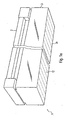
- FIGS. 1a and 1b show a lamp provided in its entirety by the reference numeral 1, which can be used, for example, in wet rooms.
- a carrier element 2 to be fastened to a ceiling a plurality of light sources in the form of oblong fluorescent lamps 10 are arranged, which are surrounded by a transparent cover 3.
- the trough-shaped cover 3 closes airtight with the carrier element 2, so that there is no risk that the light sources 10 arranged in the inner space formed thereby will be damaged by external influences, for example increased humidity.
- a light grid 11 is further arranged with a plurality of transverse blades 10, via which the light emitted by the light sources 10 down to a predetermined angular range is limited.
- the lower edges of the slats 12 are in FIG. 1 schematically represented by the dashed lines.
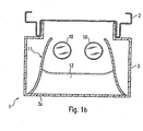
- the effect of the grid 11 should not be affected by the transparent cover 3. That is, by the bottom 3a of the transparent cover 3 escaping light rays should be scattered as little as possible in order not to change the predetermined by the grid 11 angular range later. At the same time, extraneous light occurring externally on the underside 3a should be scattered as effectively as possible, so that no gating effects occur.
- the structuring of the transparent cover 3 designed to solve this problem according to the invention will now be described with reference to FIGS FIGS. 2 and 3 be explained in more detail.
- FIG. 2 shows first an enlarged section of the transparent bottom 3a of the cover 3 in plan view.
- the outside of the emission surface 3a that is to say the surface facing away from the light sources, is provided with a multiplicity of lenticular projections 4.
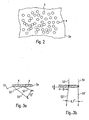
- the projections 4 are statistically distributed, so they have no regular arrangement. Its diameter D is less than 1mm and the ratio between depth T and diameter D (see FIG. 3b ) of a projection is less than 1:10.
- the optical effects achieved thereby are in the FIGS. 3a and 3b shown.
- FIG. 3a first shows the influence of the surface structured according to the invention to extraneous light, that is to say, to light rays impinging on the outside. Shown here are two parallel light beams S1 and S2, which impinge slightly offset from each other on the outside of the transparent radiating surface 3a. Since the beams S1, S2 impinge at different points, different angles of incidence result, so that both beams are reflected in different ways, that is, with different angles of rejection. As a result, the beams S1 'and S2' reflected back from the surface 3a have different directions and enclose an angle of about 15 ° with each other. This "quasi-scattering" avoids reflection effects and thus achieves the desired non-greasy appearance of the surface.
- the transparent cover according to the invention can be made of plastic in the usual way, for example of polymethyl methacrylate PMMA, and is preferably produced as usual by injection molding.
- the injection molding tool In order to achieve the desired structuring of the outside, the injection molding tool must be designed accordingly. This can be achieved, for example, by providing the outer surface of the injection molding tool with small, statistically distributed dome-shaped recesses. As already mentioned, this can be done by hammering the surface with a lenticular tool or by irradiating it with small balls, in particular steel balls.
- dome-shaped recesses are to be produced on the light exit element 3a
- the surface of the injection mold must be provided with lenticular projections. This can be achieved by an intermediate step in the form of a galvanic impression of the injection molding tool, which, however, is significantly more expensive compared to the two abovementioned possibilities.
- a method or an injection molding tool is thus preferably used, are achieved with the lenticular projections on the outside of the cover.
- the inventive design of the transparent light exit element is thus achieved that passing through the exit element light beams are no longer or only slightly influenced later.
- the optical effect of light-guiding elements is thus not disturbed by the cover according to the invention.
- extraneous light impinging on the outside of the cover is scattered relatively strongly, so that undesired reflection effects are suppressed.
- the structuring according to the invention of the transparent light exit element can be achieved in a relatively simple manner.
- the present invention is not limited to wet room lights or trough-shaped transparent covers.
- transparent - and possibly also colored - light exit elements could basically be configured in the manner according to the invention, provided that the two effects mentioned above are to be achieved. In any case, this can give the light exit elements a higher-quality appearance.
Abstract
Description
Die vorliegende Erfindung betrifft eine Leuchte mit einem transparenten Lichtaustrittselement gemäß dem Oberbegriff des Anspruchs 1 sowie ein transparentes Lichtaustrittselement und ein Verfahren zum Herstellen desselben.The present invention relates to a luminaire with a transparent light exit element according to the preamble of claim 1 and to a transparent light exit element and a method for producing the same.
Leuchten enthalten oftmals transparente Lichtaustrittselemente oder Abdeckungen, über welche zumindest ein Teil des von den Lichtquellen erzeugten Lichts abgegeben wird. Der Grund für die Verwendung dieser transparenten Lichtaustrittselemente kann vielfältig sein. Oftmals haben transparente Abdeckungen beispielsweise die Aufgabe, die Lichtquellen sowie die weiteren elektrischen Komponenten der Leuchte vor Umgebungseinflüssen zu schützen. So werden in Räumen mit einer hohen Luftfeuchtigkeit beispielsweise sogenannte Feuchtraumleuchten und in Räumen mit hoher Staubbelastung sogenannte staubgeschützte Leuchten eingesetzt, bei denen die Lichtquellen von einem wannenförmigen transparenten Gehäuse abgedeckt und luftdicht umschlossen sind. Im Allgemeinen werden derartige Leuchten als sog. "Leuchten höherer Schutzart" bezeichnet. Ein weiterer Verwendungszweck für transparente Abdeckungen kann auch darin bestehen, die Abstrahlcharakteristik der Leuchte zu beeinflussen, was z.B. durch entsprechende Prismenstrukturen an der Außen- oder Innenseite der Abdeckung erzielt wird, welche die Lichtstrahlen in eine gewünschte Richtung bündeln bzw. ablenken. Ferner werden die transparenten Lichtaustrittselemente oder Abdeckungen in bestimmten Fällen auch eingefärbt, um dem abgestrahlten Licht eine gewünschte Farbe zu verleihen.Lights often contain transparent light exit elements or covers, via which at least a portion of the light generated by the light sources is emitted. The reason for using these transparent light exit elements can be manifold. Transparent covers, for example, often have the task of protecting the light sources and the other electrical components of the luminaire from environmental influences. Thus, for example, so-called damp-proof luminaires are used in rooms with a high level of humidity, and so-called dust-proof luminaires in rooms with high dust levels, in which the light sources are covered by a trough-shaped transparent housing and enclosed in an airtight manner. In general, such lights are referred to as so-called "lights higher degree of protection". Another use for transparent covers may also be to influence the radiation characteristics of the luminaire, which may be e.g. is achieved by corresponding prismatic structures on the outside or inside of the cover, which concentrate or deflect the light rays in a desired direction. Further, in some cases, the transparent light emitting elements or covers are also colored to give the emitted light a desired color.
Bei einer aus der
Transparente Abdeckkörper der eingangs beschriebenen Art werden in der Regel durch ein Spritzgieß- oder Blasverfahren hergestellt, bei dem der flüssige Kunststoff in eine Wannenform - das Werkzeug - eingebracht und abgekühlt wird. Die Wannenform ist glatt, was zur Folge hat, dass die fertige Abdeckung an ihrer Oberfläche ebenfalls glatt ist und damit für unter größeren Einfallswinkeln auftreffende Lichtstrahlen spiegelnd wirkt. Dies erweist sich im Gebrauch allerdings als nachteilig, da Fremd- bzw. Außenlicht an der Außenseite der Abdeckung reflektiert wird und damit einen unerwünschten Effekt hervorruft. Darüber hinaus hat sich in letzter Zeit herausgestellt, dass Abdeckungen bzw. Lichtaustrittselemente mit einer glatten Oberfläche als optisch weniger ansprechend angesehen werden, da aufgrund der Spiegelungen den Eindruck erweckt wird, als wären sie mit fettigen oder ölhaltigen Stoffen verschmiert.Transparent cover body of the type described above are usually prepared by an injection molding or blow molding, in which the liquid plastic in a trough shape - the tool - is introduced and cooled. The tub shape is smooth, with the result that the finished cover is also smooth on its surface and thus acts as a mirror for incident at larger angles of incidence light rays. However, this proves to be disadvantageous in use, since extraneous or external light is reflected on the outside of the cover and thus causes an undesirable effect. In addition, it has recently been found that covers or light exit elements with a smooth surface are considered to be less visually appealing, since the reflections give the impression that they are smeared with greasy or oily substances.
Um diese unerwünschten Effekte zu vermeiden, ist bislang bekannt, die Außenseite der transparenten Abstrahlelemente aufzurauhen. Dies kann beispielsweise durch Erodieren, Sandstrahlen oder Ätzen bewirkt werden. Eine auf diese Weise bearbeitete transparente Abdeckung ist beispielsweise aus der
Dokument
Die europaïsche
Der vorliegenden Erfindung liegt daher die Aufgabe zugrunde, eine Abdeckung bzw. ein transparentes Lichtaustrittselement für eine Leuchte derart zu gestalten, dass die oben erwähnten Nachteile bezüglich unerwünschter Reflexionen an der Außenseite vermieden werden, andererseits die lichtlenkende Wirkung von in der Leuchte angeordneten Lichtbeeinflussungselementen wie beispielsweise Reflektoren oder Raster nicht maßgeblich gestört wird.The present invention is therefore based on the object to make a cover or a transparent light exit element for a lamp such that the above-mentioned disadvantages are avoided with respect to unwanted reflections on the outside, on the other hand, the light-directing effect of arranged in the lamp light influencing elements such as reflectors or grid is not significantly disturbed.
Die Aufgabe wird durch eine Leuchte mit den Merkmalen des Anspruchs 1 bzw. durch ein Lichtaustrittselement gemäß Anspruch 9 gelöst.The object is achieved by a luminaire with the features of claim 1 or by a light exit element according to claim 9.
Die erfindungsgemäße Leuchte weist zunächst mindestens eine Lichtquelle sowie ein in Lichtabstrahlrichtung gesehen vor der Lichtquelle angeordnetes transparentes Lichtaustrittselement auf. Dabei ist das Lichtaustrittselement an seiner Außenseite, das heißt an seiner der Lichtquelle abgewandten Oberfläche mit linsenförmigen Vorsprüngen oder kalottenförmigen Rücksprüngen, die keine regelmäßige Anordnung aufweisen, versehen. Erfindungsgemäß werden die linsenförmigen Vorsprünge beziehungsweise kalottenförmigen Rücksprünge hinsichtlich ihrer Abmessungen dabei derart gewählt, dass bei einer Transmission von Licht eine Ablenkung eines Lichtstrahls von maximal 5 Grad auftritt. Dies wird dadurch erreicht, dass das Verhältnis der Tiefe eines Vorsprungs bzw. Rücksprungs zum Durchmesser kleiner als 1:10 ist. Die Vorsprünge bzw. Rücksprünge sind dabei äußerst klein und weisen einen Durchmesser von weniger als 1 mm auf.The luminaire according to the invention initially has at least one light source and a transparent light exit element arranged in front of the light source, viewed in the light emission direction. In this case, the light exit element on its outer side, that is, on its surface facing away from the light source with lenticular projections or dome-shaped recesses, which have no regular arrangement provided. According to the lens-shaped projections or dome-shaped recesses are chosen in terms of their dimensions such that at a transmission of light a Distraction of a light beam of a maximum of 5 degrees occurs. This is achieved by making the ratio of the depth of a projection or return to the diameter smaller than 1:10. The projections or recesses are extremely small and have a diameter of less than 1 mm.
Wie nachfolgend erläutert wird, ermöglicht es die erfindungsgemäße Ausgestaltung des Lichtaustrittselements, die gewünschten optischen Eigenschaften zu erzielen. Hierbei wird insbesondere auf die Außenseite des Lichtaustrittselements auftreffendes Fremdlicht verhältnismäßig stark gestreut, während hingegen von der Lichtquelle der Leuchte stammendes und durch das Lichtaustrittselement hindurchtretendes Licht nur geringfügig abgelenkt wird. Auf diese Weise wird zum einen erreicht, dass an bzw. in der Leuchte vorgesehene Lichtbeeinflussungselemente wie Raster oder Reflektoren nach wie vor ihre Funktion erfüllen können, andererseits die Außenseite des Lichtaustrittselements nicht mehr spiegelt. Hierdurch wird der Leuchte insgesamt gesehen ein höherwertiges Aussehen verliehen ohne allerdings die Abstrahlungscharakteristik der Leuchte maßgeblich zu beeinflussen.As will be explained below, the inventive design of the light exit element makes it possible to achieve the desired optical properties. In this case, extraneous light incident on the outer side of the light exit element is scattered relatively strongly, whereas, on the other hand, light originating from the light source of the luminaire and passing through the light exit element is deflected only slightly. In this way, on the one hand, it is achieved that light influencing elements, such as gratings or reflectors, provided on or in the luminaire can still fulfill their function, and, on the other hand, no longer reflects the outside of the light exit element. As a result, the overall appearance of the lamp is given a higher-quality appearance without, however, significantly influencing the radiation characteristics of the luminaire.
Die Herstellung des erfindungsgemäßen Lichtaustrittselements erfolgt wiederum vorzugsweise durch ein Spritzguss- oder Blasverfahren. In diesem Fall muss dann das Spritzgusswerkzeug entsprechend modifiziert werden, um die gewünschte Struktur des Lichtaustrittselements zu erzielen. Dies bedeutet, dass die der Außenseite des Lichtaustrittselements entsprechende Oberfläche des Werkzeugs entsprechend gestaltet werden muss, was beispielsweise dadurch erreicht wird, dass die Oberfläche mit einem Werkzeug, welches einen linsenförmigen Kopf hat, gehämmert wird. Hierbei entstehen eine Vielzahl kalottenförmiger Rücksprünge, die keine regelmäßige Anordnung aufweisen, so dass das fertige Lichtaustrittselement dann letztendlich entsprechende linsenförmige Vorsprünge aufweist. Eine alternative Möglichkeit besteht darin, die Oberfläche des Werkzeugs mit kleinen Stahlkugeln zu bestrahlen, wodurch auf besonders effektive Weise der gewünschte statistische Effekt, die unregelmäßige Anordnung der Vorsprünge, erzielt wird. Selbstverständlich bestünde auch die Möglichkeit, die Werkzeugoberfläche mit linsenförmigen Vorsprüngen zu versehen und damit in dem Lichtaustrittselement kalottenförmiger Rücksprünge zu erzielen, der Aufwand zur Herstellung eines entsprechenden Spritzgusswerkzeugs ist allerdings deutlich höher als bei den beiden zuvor geschilderten Varianten.The production of the light exit element according to the invention is again preferably carried out by an injection molding or blow molding process. In this case, the injection molding tool must then be modified accordingly in order to achieve the desired structure of the light exit element. This means that the surface of the tool corresponding to the outside of the light exit element has to be designed accordingly, which is achieved, for example, by hammering the surface with a tool which has a lenticular head. This results in a plurality of dome-shaped recesses, which do not have a regular arrangement, so that the finished light exit element then ultimately has corresponding lenticular projections. An alternative possibility is to irradiate the surface of the tool with small steel balls, which is achieved in a particularly effective manner, the desired statistical effect, the irregular arrangement of the projections. Of course, there would also be the possibility of providing the tool surface with lens-shaped projections and thus achieving dome-shaped recesses in the light exit element, but the outlay for producing a corresponding injection molding tool is significantly higher than in the case of the two previously described variants.
Die vorliegende Erfindung betrifft demzufolge auch ein Verfahren zum Herstellen eines transparenten Lichtaustrittselements, bei dem zunächst ein transparentes Kunststoffmaterial in flüssiger Form in ein einen Hohlraum bildendes Spritzgießwerkzeug eingebracht und nach dem Erhärten des Kunststoffmaterials das Lichtaustrittselement aus dem Spritzgießwerkzeug entformt wird, wobei ein Spritzgießwerkzeug verwendet wird, welches erfindungsgemäß in der oben beschriebenen Weise ausgestaltet ist. Darüber hinaus betrifft die vorliegende Erfindung auch ein entsprechend gestaltetes Spritzgusswerkzeug.The present invention accordingly also relates to a method for producing a transparent light exit element, in which initially a transparent plastic material in liquid form is introduced into an injection mold forming a cavity and after hardening of the plastic material the light exit element is removed from the injection mold using an injection mold, which is designed according to the invention in the manner described above. Moreover, the present invention also relates to a suitably designed injection molding tool.
Nachfolgend soll die Erfindung anhand der beiliegenden Zeichnung näher erläutert werden. Es zeigen:
- Fig. 1a
- ein Ausführungsbeispiel der vorliegenden Erfindung in Form einer Leuchte mit einer wannenförmigen Abdeckung, wobei die transparente Abdeckung entsprechend der vorliegenden Erfindung ausgestaltet ist;
- Fig. 1b
- die Leuchte aus
Fig. 1a im Schnitt; - Fig. 2
- einen vergrößerten Ausschnitt eines erfindungsgemäßen Lichtaustrittselements in Draufsicht; und
- Fig. 3a und b
- vergrößerte Darstellungen eines erfindungsgemäßen Lichtaustrittselements im Querschnitt zur Verdeutlichung der damit erzielten optischen Effekte.
- Fig. 1a
- an embodiment of the present invention in the form of a lamp with a trough-shaped cover, wherein the transparent cover is designed according to the present invention;
- Fig. 1b
- the light off
Fig. 1a on average; - Fig. 2
- an enlarged section of a light exit element according to the invention in plan view; and
- Fig. 3a and b
- enlarged representations of a light exit element according to the invention in cross section to illustrate the optical effects achieved thereby.
Die
Innerhalb der Abdeckung 3, genauer gesagt zwischen den Lichtquellen 10 und der unteren Lichtaustrittsfläche 3a der Abdeckung 3 ist ferner ein Leuchtenraster 11 mit mehreren Querlamellen 10 angeordnet, über welches das von den Lichtquellen 10 nach unten abgestrahlte Licht auf einen vorgegebenen Winkelbereich eingeschränkt wird. Die Unterkanten der Lamellen 12 sind in
Die Wirkung des Rasters 11 sollte durch die transparente Abdeckung 3 nicht beeinflusst werden. Das heißt, durch die Unterseite 3a der transparenten Abdeckung 3 austretende Lichtstrahlen sollten möglichst wenig gestreut werden, um den durch das Raster 11 vorgegebenen Winkelbereich nicht nachträglich zu verändern. Gleichzeitig sollte allerdings von außen auf die Unterseite 3a auftretendes Fremdlicht möglichst effektiv gestreut werden, so dass keine Spielgelungseffekte auftreten. Die zum Lösen dieser Aufgabenstellung erfindungsgemäß ausgestaltete Strukturierung der transparenten Abdeckung 3 soll nunmehr anhand der
Im Gegensatz dazu werden zwei durch die Abdeckung 3 hindurchtretende Lichtstrahlen S3, S4 nur geringfügig beeinlusst, wie
Die erfindungsgemäße transparente Abdeckung kann in gewohnter Weise aus Kunststoff bestehen, beispielsweise aus Polymethylmethacrylat PMMA, und wird vorzugsweise wie üblich im Spritzgussverfahren hergestellt. Um hierbei die gewünschte Strukturierung der Außenseite zu erzielen, muss das Spritzgusswerkzeug entsprechend gestaltet werden. Dies kann beispielsweise dadurch erzielt werden, dass die der Außenseite entsprechende Oberfläche des Spritzgusswerkzeugs mit kleinen, statistisch verteilten kalottenförmigen Rücksprüngen versehen wird. Wie bereits erwähnt wurde, kann dies dadurch erfolgen, dass die Oberfläche mit einem linsenförmigen Werkzeug gehämmert oder mit kleinen Kugeln, insbesondere Stahlkugeln bestrahlt wird.The transparent cover according to the invention can be made of plastic in the usual way, for example of polymethyl methacrylate PMMA, and is preferably produced as usual by injection molding. In order to achieve the desired structuring of the outside, the injection molding tool must be designed accordingly. This can be achieved, for example, by providing the outer surface of the injection molding tool with small, statistically distributed dome-shaped recesses. As already mentioned, this can be done by hammering the surface with a lenticular tool or by irradiating it with small balls, in particular steel balls.
Sollen hingegen kalottenförmige Rücksprünge an dem Lichtaustrittselement 3a erzeugt werden, so muss die Oberfläche des Spritzgusswerkzeugs mit linsenförmigen Vorsprüngen versehen werden. Dies kann durch einen Zwischenschritt in Form einer galvanischen Abformung des Spritzgusswerkzeugs erzielt werden, was allerdings im Vergleich zu den beiden oben genannten Möglichkeiten deutlich aufwendiger ist. Für die Herstellung der transparenten Abdeckung wird somit bevorzugt ein Verfahren beziehungsweise ein Spritzgusswerkzeug verwendet, mit dem linsenförmige Vorsprünge an der Außenseite der Abdeckung erzielt werden.If, on the other hand, dome-shaped recesses are to be produced on the
Durch die erfindungsgemäße Ausgestaltung des transparenten Lichtaustrittselements wird somit erreicht, dass durch das Austrittselement hindurchtretende Lichtstrahlen nachträglich nicht mehr oder nur unwesentlich beeinflusst werden. Die optische Wirkung lichtlenkender Elemente wird somit durch die erfindungsgemäße Abdeckung nicht gestört. Gleichzeitig wird auf die Außenseite der Abdeckung auftreffendes Fremdlicht verhältnismäßig stark gestreut, so dass ungewünschte Spiegelungseffekte unterdrückt werden. Die erfindungsgemäße Strukturierung des transparenten Lichtaustrittselements kann dabei auf eine verhältnismäßig einfache Weise erzielt werden.The inventive design of the transparent light exit element is thus achieved that passing through the exit element light beams are no longer or only slightly influenced later. The optical effect of light-guiding elements is thus not disturbed by the cover according to the invention. At the same time, extraneous light impinging on the outside of the cover is scattered relatively strongly, so that undesired reflection effects are suppressed. The structuring according to the invention of the transparent light exit element can be achieved in a relatively simple manner.
Abschließend soll angemerkt werden, dass die vorliegende Erfindung nicht auf Feuchtraumleuchten oder wannenförmige transparente Abdeckungen beschränkt ist. Selbstverständlich könnten transparente - und ggf. auch gefärbte - Lichtaustrittselemente grundsätzlich in der erfindungsgemäßen Weise ausgestaltet werden, sofern die beiden oben genannten Effekte erzielt werden sollen. In jedem Fall kann hierdurch den Lichtaustrittselementen ein höherwertiges Aussehen verliehen werden.Finally, it should be noted that the present invention is not limited to wet room lights or trough-shaped transparent covers. Of course, transparent - and possibly also colored - light exit elements could basically be configured in the manner according to the invention, provided that the two effects mentioned above are to be achieved. In any case, this can give the light exit elements a higher-quality appearance.
Claims (15)
- Luminaire (1) having at least one light source (10) and a transparent light-exit element (3) arranged - seen in emission direction - in front of the light source (10), wherein at least a part region of the surface (3a) of the light-exit element (3) away from the light source (10) is provided with a plurality of lenticular projections (4) or dome-shaped re-entries which do not have any regular arrangement, characterised in that
the diameter (D) of the lenticular projections (4) or dome-shaped re-entries is less than 1 mm, and in that the ratio of the depth (T) of the lenticular projections (4) or dome-shaped re-entries to the diameter (D) is smaller than 1:10. - Luminaire according to claim 1,
characterised in that
the light-exit element (3) is of a transparent plastic. - Luminaire according to claim 2,
characterised in that
the light-exit element (3) is of polymethylmethacrylate (PMMA). - Luminaire according to claim 2 or 3,
characterised in that
the light-exit element (3) is produced by injection-moulding. - Luminaire according to any preceding claim, characterised in that
a light-influencing element (11) is arranged between the light source (10) and the light-exit element (3). - Luminaire according to claim 5,
characterised in that
the light-influencing element is a luminaire raster (11). - Luminaire according to any preceding claim, characterised in that
the light-exit element (3) is configured so as to be tub-shaped. - Luminaire according to claim 7,
characterised in that
it is a luminaire of a higher protection type, in particular a moisture-proof luminaire or a dust-proof luminaire. - Tub-shaped light-exit element (3) for use with a luminaire (19), wherein the light-exit element (3) is configured so as to be transparent and is provided for arrangement - seen in emission direction - in front of a light source (10) of the luminaire (1), and at least a part region of the surface (3a) of the light-exit element (3) is provided with a plurality of lenticular projections (4) or dome-shaped re-entries which do not have any regular arrangement,
characterised in that
the diameter (D) of the lenticular projections (4) or dome-shaped re-entries is less than 1 mm, and in that the ratio of the depth (T) of the lenticular projections (4) or dome-shaped re-entries to the diameter (D) is smaller than 1:10. - Light-exit element according to claim 9, characterised in that
the light-exit element (3) is of a transparent plastic. - Light-exit element according to claim 10, characterised in that
the light-exit element (3) is of polymethylmethacrylate (PMMA). - Light-exit element according to claim 10 or 11, characterised in that
the light-exit element (3) is produced by injection-moulding. - Method for the production of a transparent light-exit element (3) according to any of claims 9 to 12, wherein firstly a transparent plastic material in liquid form is brought into an injection-moulding tool forming a cavity, and after the hardening of the plastic material the light-exit element (3) is demoulded from the injection-moulding tool and wherein at least a part region of the surface of the injection-moulding tool corresponding to the outer side of the light-exit element (3) is provided with a plurality of lenticular projections or dome-shaped re-entries which do not have any regular arrangement,
characterised in that
the diameter (D) of the lenticular projections (4) or dome-shaped re-entries is less than 1 mm, and in that the ratio of the depth (T) of the lenticular projections (4) or dome-shaped re-entries to the diameter (D) is smaller than 1:10. - Method according to claim 13,
characterised in that
the plastic is polymethylmethacrylate (PMMA). - Injection-moulding tool for the production of a transparent light-exit element (3) according to any of the claims 9 to 12,
wherein at least a part region of the surface of the injection-moulding tool corresponding to the outer side of the light-exit element (3) is provided with a plurality of statistically lenticular projections or dome-shaped re-entries which do not have any regular arrangement,
characterised in that
the diameter (D) of the lenticular projections (4) or dome-shaped re-entries is less than 1 mm, and in that the ratio of the depth (T) of the lenticular projections (4) or dome-shaped re-entries to the diameter (D) is smaller than 1:10.
Applications Claiming Priority (2)
| Application Number | Priority Date | Filing Date | Title |
|---|---|---|---|
| DE10354463A DE10354463A1 (en) | 2003-11-21 | 2003-11-21 | Luminaire with transparent light exit element |
| PCT/EP2004/013127 WO2005050087A1 (en) | 2003-11-21 | 2004-11-18 | Lamp comprising a transparent light-emerging element |
Publications (3)
| Publication Number | Publication Date |
|---|---|
| EP1685348A1 EP1685348A1 (en) | 2006-08-02 |
| EP1685348B1 EP1685348B1 (en) | 2008-08-06 |
| EP1685348B2 true EP1685348B2 (en) | 2014-07-09 |
Family
ID=34609203
Family Applications (1)
| Application Number | Title | Priority Date | Filing Date |
|---|---|---|---|
| EP04797994.3A Not-in-force EP1685348B2 (en) | 2003-11-21 | 2004-11-18 | Lamp comprising a transparent light-emerging element |
Country Status (4)
| Country | Link |
|---|---|
| EP (1) | EP1685348B2 (en) |
| AT (1) | ATE403830T1 (en) |
| DE (2) | DE10354463A1 (en) |
| WO (1) | WO2005050087A1 (en) |
Families Citing this family (4)
| Publication number | Priority date | Publication date | Assignee | Title |
|---|---|---|---|---|
| KR20100019992A (en) | 2007-05-09 | 2010-02-19 | 코닌클리즈케 필립스 일렉트로닉스 엔.브이. | A cover for a light source |
| DE202008016131U1 (en) * | 2008-12-05 | 2009-03-12 | Ivl Lammert Trading Gmbh & Co. Kg | fluorescent tube |
| DE102009016566A1 (en) † | 2009-04-06 | 2010-10-07 | Zumtobel Lighting Gmbh | Cover light with circumferential sealing lip |
| WO2019048511A1 (en) | 2017-09-07 | 2019-03-14 | Signify Holding B.V. | Improved comfort of outdoor luminaires due to phyllotactic arrangement of led sources |
Family Cites Families (9)
| Publication number | Priority date | Publication date | Assignee | Title |
|---|---|---|---|---|
| DE945835C (en) * | 1951-02-04 | 1956-07-19 | Bosch Gmbh Robert | Translucent cover for vehicle headlights |
| EP0221416B1 (en) * | 1985-11-07 | 1995-09-27 | Robert Bosch Gmbh | Dipped-beam head light or fog light for motor vehicles |
| DE8706137U1 (en) | 1987-04-29 | 1987-06-11 | Trilux-Lenze Gmbh + Co Kg, 5760 Arnsberg, De | |
| US4868458A (en) * | 1988-02-18 | 1989-09-19 | General Electric Company | Xenon lamp particularly suited for automotive applications |
| US4991073A (en) * | 1989-03-08 | 1991-02-05 | Gte Products Corporation | Lighting lens |
| DE9104316U1 (en) * | 1991-04-10 | 1991-06-13 | Zumtobel Ag, Dornbirn, At | |
| JP5054872B2 (en) * | 2001-02-22 | 2012-10-24 | 恵和株式会社 | Light diffusion sheet and backlight unit using the same |
| DE20112365U1 (en) | 2001-07-27 | 2002-12-05 | Zumtobel Staff Gmbh | Luminaire with a base part and a trough-shaped cover and base part for a luminaire |
| DE10242441A1 (en) * | 2002-09-11 | 2004-04-01 | Erco Leuchten Gmbh | lamp |
-
2003
- 2003-11-21 DE DE10354463A patent/DE10354463A1/en not_active Withdrawn
-
2004
- 2004-11-18 DE DE502004007800T patent/DE502004007800D1/en active Active
- 2004-11-18 WO PCT/EP2004/013127 patent/WO2005050087A1/en active IP Right Grant
- 2004-11-18 EP EP04797994.3A patent/EP1685348B2/en not_active Not-in-force
- 2004-11-18 AT AT04797994T patent/ATE403830T1/en active
Also Published As
| Publication number | Publication date |
|---|---|
| DE502004007800D1 (en) | 2008-09-18 |
| EP1685348A1 (en) | 2006-08-02 |
| WO2005050087A1 (en) | 2005-06-02 |
| DE10354463A1 (en) | 2005-06-23 |
| ATE403830T1 (en) | 2008-08-15 |
| EP1685348B1 (en) | 2008-08-06 |
Similar Documents
| Publication | Publication Date | Title |
|---|---|---|
| DE10124370B4 (en) | Optical element with total reflection | |
| DE102004026530B3 (en) | optical body | |
| DE19827264B4 (en) | Vehicle lamp with improved optical design | |
| DE102008063369A1 (en) | lamp | |
| EP2259098B1 (en) | Display device | |
| EP1398562A1 (en) | Luminaire producing sharply delimited light cone | |
| WO2009127464A1 (en) | Vehicle lamp | |
| EP0658780B1 (en) | Directional filter for lighting fixture and method of manufacture | |
| WO2005066537A1 (en) | Built-in light | |
| EP1338845B1 (en) | Lamp | |
| EP2102545B1 (en) | Transparent plate with a surface structure for the largely glare-free emission of the light generated by a lamp | |
| DE3224256C2 (en) | Light, in particular for the signal system of motor vehicles | |
| EP1685348B2 (en) | Lamp comprising a transparent light-emerging element | |
| EP3228931A1 (en) | Light guide with light deflection structures | |
| EP2989381B1 (en) | Arrangement for light output comprising an led light source and a reflector | |
| DE2225969C2 (en) | Luminaire cover plate | |
| EP1359371B1 (en) | Luminaire with a diffuser | |
| EP2295851A2 (en) | Light influencing element | |
| WO2021058167A1 (en) | Luminaire having a region for emitting light over a surface | |
| EP0889284B1 (en) | Vehicle light | |
| EP3748226A1 (en) | Reflector for a light | |
| DE102009012210A1 (en) | Bowl-shaped reflector for light fixture arranged in interior of lamp, has inner side having multiple facets, where multiple adjacent facets form wave | |
| EP1900998B1 (en) | Reflector with a structure featuring light | |
| EP1132679A1 (en) | Lighting system | |
| DE10354462B4 (en) | Luminaire with asymmetrical light emission |
Legal Events
| Date | Code | Title | Description |
|---|---|---|---|
| PUAI | Public reference made under article 153(3) epc to a published international application that has entered the european phase |
Free format text: ORIGINAL CODE: 0009012 |
|
| 17P | Request for examination filed |
Effective date: 20060427 |
|
| AK | Designated contracting states |
Kind code of ref document: A1 Designated state(s): AT BE BG CH CY CZ DE DK EE ES FI FR GB GR HU IE IS IT LI LU MC NL PL PT RO SE SI SK TR |
|
| DAX | Request for extension of the european patent (deleted) | ||
| 17Q | First examination report despatched |
Effective date: 20071010 |
|
| GRAP | Despatch of communication of intention to grant a patent |
Free format text: ORIGINAL CODE: EPIDOSNIGR1 |
|
| RIC1 | Information provided on ipc code assigned before grant |
Ipc: F21Y 103/00 20060101ALI20080317BHEP Ipc: F21V 5/00 20060101AFI20080317BHEP |
|
| GRAS | Grant fee paid |
Free format text: ORIGINAL CODE: EPIDOSNIGR3 |
|
| GRAA | (expected) grant |
Free format text: ORIGINAL CODE: 0009210 |
|
| AK | Designated contracting states |
Kind code of ref document: B1 Designated state(s): AT BE BG CH CY CZ DE DK EE ES FI FR GB GR HU IE IS IT LI LU MC NL PL PT RO SE SI SK TR |
|
| REG | Reference to a national code |
Ref country code: GB Ref legal event code: FG4D Free format text: NOT ENGLISH |
|
| REG | Reference to a national code |
Ref country code: CH Ref legal event code: EP |
|
| REG | Reference to a national code |
Ref country code: IE Ref legal event code: FG4D Free format text: LANGUAGE OF EP DOCUMENT: GERMAN |
|
| REF | Corresponds to: |
Ref document number: 502004007800 Country of ref document: DE Date of ref document: 20080918 Kind code of ref document: P |
|
| REG | Reference to a national code |
Ref country code: CH Ref legal event code: NV Representative=s name: RIEDERER HASLER & PARTNER PATENTANWAELTE AG |
|
| PG25 | Lapsed in a contracting state [announced via postgrant information from national office to epo] |
Ref country code: ES Free format text: LAPSE BECAUSE OF FAILURE TO SUBMIT A TRANSLATION OF THE DESCRIPTION OR TO PAY THE FEE WITHIN THE PRESCRIBED TIME-LIMIT Effective date: 20081117 Ref country code: NL Free format text: LAPSE BECAUSE OF FAILURE TO SUBMIT A TRANSLATION OF THE DESCRIPTION OR TO PAY THE FEE WITHIN THE PRESCRIBED TIME-LIMIT Effective date: 20080806 Ref country code: IS Free format text: LAPSE BECAUSE OF FAILURE TO SUBMIT A TRANSLATION OF THE DESCRIPTION OR TO PAY THE FEE WITHIN THE PRESCRIBED TIME-LIMIT Effective date: 20081206 |
|
| PG25 | Lapsed in a contracting state [announced via postgrant information from national office to epo] |
Ref country code: FI Free format text: LAPSE BECAUSE OF FAILURE TO SUBMIT A TRANSLATION OF THE DESCRIPTION OR TO PAY THE FEE WITHIN THE PRESCRIBED TIME-LIMIT Effective date: 20080806 Ref country code: SI Free format text: LAPSE BECAUSE OF FAILURE TO SUBMIT A TRANSLATION OF THE DESCRIPTION OR TO PAY THE FEE WITHIN THE PRESCRIBED TIME-LIMIT Effective date: 20080806 |
|
| REG | Reference to a national code |
Ref country code: IE Ref legal event code: FD4D |
|
| PG25 | Lapsed in a contracting state [announced via postgrant information from national office to epo] |
Ref country code: IE Free format text: LAPSE BECAUSE OF FAILURE TO SUBMIT A TRANSLATION OF THE DESCRIPTION OR TO PAY THE FEE WITHIN THE PRESCRIBED TIME-LIMIT Effective date: 20080806 Ref country code: BG Free format text: LAPSE BECAUSE OF FAILURE TO SUBMIT A TRANSLATION OF THE DESCRIPTION OR TO PAY THE FEE WITHIN THE PRESCRIBED TIME-LIMIT Effective date: 20081106 Ref country code: DK Free format text: LAPSE BECAUSE OF FAILURE TO SUBMIT A TRANSLATION OF THE DESCRIPTION OR TO PAY THE FEE WITHIN THE PRESCRIBED TIME-LIMIT Effective date: 20080806 |
|
| PLBI | Opposition filed |
Free format text: ORIGINAL CODE: 0009260 |
|
| PG25 | Lapsed in a contracting state [announced via postgrant information from national office to epo] |
Ref country code: SK Free format text: LAPSE BECAUSE OF FAILURE TO SUBMIT A TRANSLATION OF THE DESCRIPTION OR TO PAY THE FEE WITHIN THE PRESCRIBED TIME-LIMIT Effective date: 20080806 Ref country code: PT Free format text: LAPSE BECAUSE OF FAILURE TO SUBMIT A TRANSLATION OF THE DESCRIPTION OR TO PAY THE FEE WITHIN THE PRESCRIBED TIME-LIMIT Effective date: 20090106 Ref country code: RO Free format text: LAPSE BECAUSE OF FAILURE TO SUBMIT A TRANSLATION OF THE DESCRIPTION OR TO PAY THE FEE WITHIN THE PRESCRIBED TIME-LIMIT Effective date: 20080806 Ref country code: CZ Free format text: LAPSE BECAUSE OF FAILURE TO SUBMIT A TRANSLATION OF THE DESCRIPTION OR TO PAY THE FEE WITHIN THE PRESCRIBED TIME-LIMIT Effective date: 20080806 |
|
| BERE | Be: lapsed |
Owner name: ZUMTOBEL LIGHTING GMBH Effective date: 20081130 |
|
| PLAX | Notice of opposition and request to file observation + time limit sent |
Free format text: ORIGINAL CODE: EPIDOSNOBS2 |
|
| 26 | Opposition filed |
Opponent name: SITECO BELEUCHTUNGSTECHNIK GMBH Effective date: 20090506 |
|
| PG25 | Lapsed in a contracting state [announced via postgrant information from national office to epo] |
Ref country code: MC Free format text: LAPSE BECAUSE OF NON-PAYMENT OF DUE FEES Effective date: 20081130 |
|
| GBPC | Gb: european patent ceased through non-payment of renewal fee |
Effective date: 20081118 |
|
| PG25 | Lapsed in a contracting state [announced via postgrant information from national office to epo] |
Ref country code: EE Free format text: LAPSE BECAUSE OF FAILURE TO SUBMIT A TRANSLATION OF THE DESCRIPTION OR TO PAY THE FEE WITHIN THE PRESCRIBED TIME-LIMIT Effective date: 20080806 |
|
| PG25 | Lapsed in a contracting state [announced via postgrant information from national office to epo] |
Ref country code: IT Free format text: LAPSE BECAUSE OF FAILURE TO SUBMIT A TRANSLATION OF THE DESCRIPTION OR TO PAY THE FEE WITHIN THE PRESCRIBED TIME-LIMIT Effective date: 20080806 |
|
| REG | Reference to a national code |
Ref country code: FR Ref legal event code: ST Effective date: 20090731 |
|
| PG25 | Lapsed in a contracting state [announced via postgrant information from national office to epo] |
Ref country code: BE Free format text: LAPSE BECAUSE OF NON-PAYMENT OF DUE FEES Effective date: 20081130 |
|
| PLBB | Reply of patent proprietor to notice(s) of opposition received |
Free format text: ORIGINAL CODE: EPIDOSNOBS3 |
|
| PG25 | Lapsed in a contracting state [announced via postgrant information from national office to epo] |
Ref country code: GB Free format text: LAPSE BECAUSE OF NON-PAYMENT OF DUE FEES Effective date: 20081118 |
|
| PG25 | Lapsed in a contracting state [announced via postgrant information from national office to epo] |
Ref country code: SE Free format text: LAPSE BECAUSE OF FAILURE TO SUBMIT A TRANSLATION OF THE DESCRIPTION OR TO PAY THE FEE WITHIN THE PRESCRIBED TIME-LIMIT Effective date: 20081106 |
|
| PG25 | Lapsed in a contracting state [announced via postgrant information from national office to epo] |
Ref country code: PL Free format text: LAPSE BECAUSE OF FAILURE TO SUBMIT A TRANSLATION OF THE DESCRIPTION OR TO PAY THE FEE WITHIN THE PRESCRIBED TIME-LIMIT Effective date: 20080806 |
|
| PG25 | Lapsed in a contracting state [announced via postgrant information from national office to epo] |
Ref country code: HU Free format text: LAPSE BECAUSE OF FAILURE TO SUBMIT A TRANSLATION OF THE DESCRIPTION OR TO PAY THE FEE WITHIN THE PRESCRIBED TIME-LIMIT Effective date: 20090207 Ref country code: CY Free format text: LAPSE BECAUSE OF FAILURE TO SUBMIT A TRANSLATION OF THE DESCRIPTION OR TO PAY THE FEE WITHIN THE PRESCRIBED TIME-LIMIT Effective date: 20080806 Ref country code: LU Free format text: LAPSE BECAUSE OF NON-PAYMENT OF DUE FEES Effective date: 20081118 |
|
| PG25 | Lapsed in a contracting state [announced via postgrant information from national office to epo] |
Ref country code: TR Free format text: LAPSE BECAUSE OF FAILURE TO SUBMIT A TRANSLATION OF THE DESCRIPTION OR TO PAY THE FEE WITHIN THE PRESCRIBED TIME-LIMIT Effective date: 20080806 |
|
| PG25 | Lapsed in a contracting state [announced via postgrant information from national office to epo] |
Ref country code: GR Free format text: LAPSE BECAUSE OF FAILURE TO SUBMIT A TRANSLATION OF THE DESCRIPTION OR TO PAY THE FEE WITHIN THE PRESCRIBED TIME-LIMIT Effective date: 20081107 |
|
| APBM | Appeal reference recorded |
Free format text: ORIGINAL CODE: EPIDOSNREFNO |
|
| APBP | Date of receipt of notice of appeal recorded |
Free format text: ORIGINAL CODE: EPIDOSNNOA2O |
|
| APAH | Appeal reference modified |
Free format text: ORIGINAL CODE: EPIDOSCREFNO |
|
| APBQ | Date of receipt of statement of grounds of appeal recorded |
Free format text: ORIGINAL CODE: EPIDOSNNOA3O |
|
| PG25 | Lapsed in a contracting state [announced via postgrant information from national office to epo] |
Ref country code: FR Free format text: LAPSE BECAUSE OF NON-PAYMENT OF DUE FEES Effective date: 20081130 |
|
| APBU | Appeal procedure closed |
Free format text: ORIGINAL CODE: EPIDOSNNOA9O |
|
| PUAH | Patent maintained in amended form |
Free format text: ORIGINAL CODE: 0009272 |
|
| STAA | Information on the status of an ep patent application or granted ep patent |
Free format text: STATUS: PATENT MAINTAINED AS AMENDED |
|
| 27A | Patent maintained in amended form |
Effective date: 20140709 |
|
| AK | Designated contracting states |
Kind code of ref document: B2 Designated state(s): AT BE BG CH CY CZ DE DK EE ES FI FR GB GR HU IE IS IT LI LU MC NL PL PT RO SE SI SK TR |
|
| REG | Reference to a national code |
Ref country code: DE Ref legal event code: R102 Ref document number: 502004007800 Country of ref document: DE |
|
| REG | Reference to a national code |
Ref country code: CH Ref legal event code: AELC |
|
| REG | Reference to a national code |
Ref country code: DE Ref legal event code: R102 Ref document number: 502004007800 Country of ref document: DE Effective date: 20140709 |
|
| PGFP | Annual fee paid to national office [announced via postgrant information from national office to epo] |
Ref country code: CH Payment date: 20161125 Year of fee payment: 13 |
|
| PGFP | Annual fee paid to national office [announced via postgrant information from national office to epo] |
Ref country code: AT Payment date: 20161125 Year of fee payment: 13 |
|
| REG | Reference to a national code |
Ref country code: AT Ref legal event code: MM01 Ref document number: 403830 Country of ref document: AT Kind code of ref document: T Effective date: 20171118 |
|
| PG25 | Lapsed in a contracting state [announced via postgrant information from national office to epo] |
Ref country code: LI Free format text: LAPSE BECAUSE OF NON-PAYMENT OF DUE FEES Effective date: 20171130 Ref country code: CH Free format text: LAPSE BECAUSE OF NON-PAYMENT OF DUE FEES Effective date: 20171130 |
|
| PG25 | Lapsed in a contracting state [announced via postgrant information from national office to epo] |
Ref country code: AT Free format text: LAPSE BECAUSE OF NON-PAYMENT OF DUE FEES Effective date: 20171118 |
|
| REG | Reference to a national code |
Ref country code: DE Ref legal event code: R084 Ref document number: 502004007800 Country of ref document: DE |
|
| PGFP | Annual fee paid to national office [announced via postgrant information from national office to epo] |
Ref country code: DE Payment date: 20190131 Year of fee payment: 15 |
|
| REG | Reference to a national code |
Ref country code: DE Ref legal event code: R119 Ref document number: 502004007800 Country of ref document: DE |
|
| PG25 | Lapsed in a contracting state [announced via postgrant information from national office to epo] |
Ref country code: DE Free format text: LAPSE BECAUSE OF NON-PAYMENT OF DUE FEES Effective date: 20200603 |