EP3228931A1 - Light guide with light deflection structures - Google Patents
Light guide with light deflection structures Download PDFInfo
- Publication number
- EP3228931A1 EP3228931A1 EP16163636.0A EP16163636A EP3228931A1 EP 3228931 A1 EP3228931 A1 EP 3228931A1 EP 16163636 A EP16163636 A EP 16163636A EP 3228931 A1 EP3228931 A1 EP 3228931A1
- Authority
- EP
- European Patent Office
- Prior art keywords
- light
- light guide
- lichtumlenkstrukturen
- base body
- optical waveguide
- Prior art date
- Legal status (The legal status is an assumption and is not a legal conclusion. Google has not performed a legal analysis and makes no representation as to the accuracy of the status listed.)
- Withdrawn
Links
Images


Classifications
-
- G—PHYSICS
- G02—OPTICS
- G02B—OPTICAL ELEMENTS, SYSTEMS OR APPARATUS
- G02B6/00—Light guides; Structural details of arrangements comprising light guides and other optical elements, e.g. couplings
- G02B6/0001—Light guides; Structural details of arrangements comprising light guides and other optical elements, e.g. couplings specially adapted for lighting devices or systems
- G02B6/0011—Light guides; Structural details of arrangements comprising light guides and other optical elements, e.g. couplings specially adapted for lighting devices or systems the light guides being planar or of plate-like form
- G02B6/0033—Means for improving the coupling-out of light from the light guide
- G02B6/0058—Means for improving the coupling-out of light from the light guide varying in density, size, shape or depth along the light guide
- G02B6/006—Means for improving the coupling-out of light from the light guide varying in density, size, shape or depth along the light guide to produce indicia, symbols, texts or the like
-
- B—PERFORMING OPERATIONS; TRANSPORTING
- B29—WORKING OF PLASTICS; WORKING OF SUBSTANCES IN A PLASTIC STATE IN GENERAL
- B29D—PRODUCING PARTICULAR ARTICLES FROM PLASTICS OR FROM SUBSTANCES IN A PLASTIC STATE
- B29D11/00—Producing optical elements, e.g. lenses or prisms
- B29D11/00663—Production of light guides
-
- G—PHYSICS
- G02—OPTICS
- G02B—OPTICAL ELEMENTS, SYSTEMS OR APPARATUS
- G02B6/00—Light guides; Structural details of arrangements comprising light guides and other optical elements, e.g. couplings
- G02B6/0001—Light guides; Structural details of arrangements comprising light guides and other optical elements, e.g. couplings specially adapted for lighting devices or systems
- G02B6/0011—Light guides; Structural details of arrangements comprising light guides and other optical elements, e.g. couplings specially adapted for lighting devices or systems the light guides being planar or of plate-like form
- G02B6/0033—Means for improving the coupling-out of light from the light guide
- G02B6/0035—Means for improving the coupling-out of light from the light guide provided on the surface of the light guide or in the bulk of it
- G02B6/004—Scattering dots or dot-like elements, e.g. microbeads, scattering particles, nanoparticles
- G02B6/0041—Scattering dots or dot-like elements, e.g. microbeads, scattering particles, nanoparticles provided in the bulk of the light guide
-
- G—PHYSICS
- G02—OPTICS
- G02B—OPTICAL ELEMENTS, SYSTEMS OR APPARATUS
- G02B6/00—Light guides; Structural details of arrangements comprising light guides and other optical elements, e.g. couplings
- G02B6/0001—Light guides; Structural details of arrangements comprising light guides and other optical elements, e.g. couplings specially adapted for lighting devices or systems
- G02B6/0011—Light guides; Structural details of arrangements comprising light guides and other optical elements, e.g. couplings specially adapted for lighting devices or systems the light guides being planar or of plate-like form
- G02B6/0033—Means for improving the coupling-out of light from the light guide
- G02B6/0058—Means for improving the coupling-out of light from the light guide varying in density, size, shape or depth along the light guide
- G02B6/0061—Means for improving the coupling-out of light from the light guide varying in density, size, shape or depth along the light guide to provide homogeneous light output intensity
-
- G—PHYSICS
- G02—OPTICS
- G02B—OPTICAL ELEMENTS, SYSTEMS OR APPARATUS
- G02B6/00—Light guides; Structural details of arrangements comprising light guides and other optical elements, e.g. couplings
- G02B6/0001—Light guides; Structural details of arrangements comprising light guides and other optical elements, e.g. couplings specially adapted for lighting devices or systems
- G02B6/0011—Light guides; Structural details of arrangements comprising light guides and other optical elements, e.g. couplings specially adapted for lighting devices or systems the light guides being planar or of plate-like form
- G02B6/0065—Manufacturing aspects; Material aspects
-
- G—PHYSICS
- G02—OPTICS
- G02B—OPTICAL ELEMENTS, SYSTEMS OR APPARATUS
- G02B6/00—Light guides; Structural details of arrangements comprising light guides and other optical elements, e.g. couplings
- G02B6/0001—Light guides; Structural details of arrangements comprising light guides and other optical elements, e.g. couplings specially adapted for lighting devices or systems
- G02B6/0011—Light guides; Structural details of arrangements comprising light guides and other optical elements, e.g. couplings specially adapted for lighting devices or systems the light guides being planar or of plate-like form
- G02B6/0066—Light guides; Structural details of arrangements comprising light guides and other optical elements, e.g. couplings specially adapted for lighting devices or systems the light guides being planar or of plate-like form characterised by the light source being coupled to the light guide
- G02B6/0073—Light emitting diode [LED]
-
- B—PERFORMING OPERATIONS; TRANSPORTING
- B29—WORKING OF PLASTICS; WORKING OF SUBSTANCES IN A PLASTIC STATE IN GENERAL
- B29D—PRODUCING PARTICULAR ARTICLES FROM PLASTICS OR FROM SUBSTANCES IN A PLASTIC STATE
- B29D11/00—Producing optical elements, e.g. lenses or prisms
- B29D11/0074—Production of other optical elements not provided for in B29D11/00009- B29D11/0073
- B29D11/00769—Producing diffraction gratings
Definitions
- the present invention relates to a light guide having a plurality of Lichtumlenk Scheme.
- Such light guides are used in various fields of application and in particular in the automotive industry, for example for producing an illuminable display or decorative element.
- Light guides are used to carry light and are used in a wide variety of applications.
- the optical waveguide passes the light beams emitted by a light source, which are coupled into the optical waveguide, for example via a light coupling surface, in its interior to form a light decoupling surface, via which the light beams leave the optical waveguide.
- the light beams can leave the light guide diffusely in different directions or deliberately in a certain direction, for example in the direction of an observer, in order to achieve a correspondingly desired light effect.
- optical fibers An application of optical fibers is found in particular in the automotive industry.
- motor vehicles located in the interior or exterior control and operating elements to be provided with display and illumination elements, which are illuminated via a light guide from a light source behind it, the visibility of the individual controls and actuators especially at night to ensure.
- display and illumination elements which are illuminated via a light guide from a light source behind it
- decorative elements and moldings are used to indicate, for example in the form of a door sill strip on the brand name of the motor vehicle, or order to create a special effect and thereby attract the viewer's perception.
- the light guide can thus serve, in particular, to achieve a uniform illumination of the display element or decoration elements.
- Optical fibers are used here in luminaires to achieve a certain desired radiation of the light emitted by one or more light sources.
- the desired radiation can be targeted and in particular focused in a certain direction or diffused in different directions.
- the Lichtumlenk Scheme be generated by means of laser processing by local melting of the polymer material of the light guide.
- the present invention thus provides a light guide with a plurality of Lichtumlenk Cooken which are arranged in the interior of the light guide.
- the Lichtumlenk Cooken each have an elongated body, which is dimensioned along its longitudinal direction by a multiple greater than in the perpendicular to this longitudinal direction directions.
- the main body of the Lichtumlenk Vietnameseen is advantageously formed rod-shaped. Along its longitudinal direction, the basic body is thus dimensioned larger by a multiple than in all directions perpendicular to this longitudinal direction. Advantageously, it is dimensioned larger by a factor of at least 3, more advantageously of at least 5 and more advantageously of at least 10 along its longitudinal direction than in the directions perpendicular thereto at any point along its longitudinal extent. It has been found that the light extraction, in particular the targeted light extraction, from the light guide is the more efficient, the elongated are the main body of Lichtumlenk Modellen.
- the Lichtumlenk Scheme Since the Lichtumlenk Scheme are arranged in the interior of the light guide, damage to the light guide surface has little or no effect on the function of the light guide, as far as its Lichtabstrahl characterizing.
- the Lichtumlenk Scheme be completely disposed in the interior of the light guide, that is completely surrounded by the material of the light guide.
- the light deflection structures are preferably produced by a local material change, in particular by melting of the material, of the light guide.
- the material of the optical waveguide is therefore preferably melted at the corresponding points by means of heat for the production of Lichtumlenk Vietnameseen and cooled again. It is thereby effected at the respective locations a local structural change of the optical fiber material, whereby the Lichtumlenk Vietnameseen are formed.
- the material of the light guide is preferably not carbonized in the manufacture of the light redirecting structures.
- the material of the light guide is preferably plastic, glass or an elastomer.
- the light guide is also made of a transparent material.
- the plastic may be, for example, polymethyl methacrylate (PMMA), polycarbonate (PC) or polymethacrylmethyl imide (PMMI).
- the elastomer may be, for example, silicone.
- the Lichtumlenk Weghoff Weghoff Weghoff Weghoff Weghoff Weghoff Weghoff Weghoff (2015) are made by means of a laser.
- the laser light in each case preferably effects a local heat input at the corresponding points in the optical waveguide, which leads to a material melting.
- the production of Lichtumlenk Vietnameseen by means of a laser is not only particularly simple, but can also be carried out simply such that the mentioned elongated body and the local thickening and flags given below arise.
- the production of Lichtumlenk Vietnamese devisen by means of a laser can be ensured that the material is locally melted, but not carbonized.
- the Lichtumlenk Weghoff Weghoff Weghoff Weghoff Weghoff (2015) but also by any other methods known in the art can be produced.
- the present invention thus also relates to a process for the preparation a light guide, which is formed as indicated.
- the light guide is irradiated with a laser to form a plurality of Lichtumlenk Modellen, each with an elongated body in the interior of the light guide.
- the Lichtumlenk Vietnamese pieces are preferably made using green laser light.
- the green laser light has a wavelength in the range of 490 nm - 575 nm.
- an ultrashort pulse laser more preferably a femtosecond laser or a picosecond laser, is used.
- the main body of the Lichtumlenk Vietnameseen is each substantially rotationally symmetric, in particular completely rotationally symmetrical.
- the Lichtumlenk Vietnameseen are thus easier to manufacture, and caused by the Lichtumlenk Vietnameseen light deflection is easier vorausrechbar.
- a luminance simulation software can be created in order to predict the luminance at the surface and in particular at the light outcoupling surface of the light guide, or vice versa, starting from a desired surface luminance to determine the arrangement and / or formation of the Lichtumlenk Modellen within the light guide. In this way, it is very easy to achieve any desired luminance distribution on the optical waveguide surface. Due to the rotational symmetry of the base body, the longitudinal axis of the respective Lichtumlenk Cook is determined, which coincides with the axis of symmetry.
- luminance is understood to mean the ratio of the luminous intensity to the size of the visible luminous light output surface, which is given in candelas per square meter of the light outcoupling surface (cd / m 2 ).
- At least one base body has a local thickening along its longitudinal direction, and all the base bodies preferably have a local thickening along their longitudinal direction.
- the local thickening is preferably arranged decentralized in the main body along the longitudinal direction of the main body, that is not exactly in the middle of the main body. It has been shown that a major part of the side to the Lichtumlenk Scheme Design incident light rays in the direction of the longitudinal axis of the body is deflected out.
- the thickening preferably has a circular cross-section perpendicular to the longitudinal axis of the main body.
- the thickening with respect to the longitudinal direction of the base body is arranged at 15-35% of the total longitudinal extent of the base body.
- the diameter of the thickening, measured in a direction perpendicular to the longitudinal axis of the base body, is preferably not greater than 30 microns.
- the main bodies of the light deflecting structures extend substantially parallel along their respective longitudinal direction, preferably completely parallel to one another. It can thereby be achieved, for example, that the light irradiated into the light guide is coupled to a predominant majority of two mutually opposite, preferably flat outer surfaces of the light guide.
- the term flag refers to the shape of the Lichtumlenk Modellen and is to be understood as an attached to the basic structure flap-shaped part.
- the flag or flags preferably have an overall approximately quadrangular shape, wherein they extend predominantly along two dimensions in a surface, which may be particularly flat.
- the at least one flag usually has a thickness which is dimensioned smaller compared to the side lengths of the flag in the surface along the first two dimensions by a multiple.
- the at least one flag is at most 5 ⁇ m thick.
- the at least one flag along one of its four sides, in particular along an entire side length, connected to the main body.
- the flag (s) thus serve to improve the efficiency of the light deflection.
- At least one lug of the at least one lug extends over 1/3 to 2/3 of the total longitudinal extent of the basic body.
- the at least one flag may in particular be connected along one of its sides over a range of 1/3 to 2/3 of the total longitudinal extent of the main body with this.
- the width of the flag, measured in a direction perpendicular to the longitudinal axis of the base body, is preferably at most 30 microns.
- the main body is in one or more parts, preferably formed in one piece. If the base body is designed in several parts, the base body is preferably constructed in at least two parts. If the base body is constructed at least in two parts, the at least two parts of the base body are preferably spaced apart from one another. Preferably, the at least two parts are connected to each other by means of at least one flag.
- the Lichtumlenk Cook are advantageous, however, each formed integrally as a whole, that is, they have no spaced-apart parts that are not connected to each other by another part of the same Lichtumschtechnik Design.
- At least two flags are attached to the main body.
- the two flags are advantageously mounted on substantially diametrically opposite sides of the base body and extending in particular in opposite radial directions away from the body.
- the light guide preferably has a light outcoupling surface, via which the light radiated into the light guide by a light source is radiated outwards.
- the main bodies of the light deflecting structures are in each case substantially perpendicular to this light outcoupling surface with their longitudinal directions, that is to say longitudinal axes.
- the main bodies of the light deflecting structures preferably each have a longitudinal extent of at least 100 ⁇ m, more preferably of at least 300 ⁇ m.
- the Lichtumlenk Scheme or their body are advantageously at most 800 microns long. Lichtumlenk Scheme which have a greater longitudinal extent are visible to the human eye, which is not desirable in most cases. Concerning. The visibility for the human eye is assumed here and below in each case by a distance of about 30 cm - 70 cm from the light output surface.
- the light deflecting structures are invisible when, in the unlit state, the region of the optical waveguide with the light deflecting structures can hardly be distinguished from such a distance by a viewer from a region of the optical waveguide which has no light deflecting structures.
- the individual Lichtumlenk Scheme are then hardly recognizable.
- the Lichtumlenk Vietnameseen at regular or irregular intervals, preferably at regular intervals, each other in the light guide.
- the distances between the Lichtumlenk Vietnameseen are preferably at least 50 .mu.m, more preferably at least 80 .mu.m, in particular at least 100 .mu.m.
- the light deflection structures should have distances between each other of preferably not more than 400 ⁇ m, more preferably not more than 200 ⁇ m, in particular not more than 150 ⁇ m.
- the main body of the light deflecting structures of the optical waveguide preferably has a circular cross-sectional area with a center M, perpendicular to its longitudinal direction, in particular in the region of any thickening of the main body, wherein a maximum diameter d of the circular cross-sectional area of the main body of a respective Lichtumlenk Vietnamese is 30 microns or less , and wherein the distance A between the centers M of the circular cross-sectional area of the main body of the Lichtumlenk Scheme devisen of the light guide at least 50 microns.
- This advantageous embodiment has the advantage that the light deflection structures of the light guide are hardly visible to the eye in the unlit state of the light guide.
- the main body of the Lichtumlenk devise perpendicular to its longitudinal direction, in particular in the region of any existing thickening of the body, a circular cross-sectional area, that is, a cross-sectional area which is bordered by an outer boundary line, which forms at least approximately, in particular substantially a circle ,
- This outer boundary line has in particular a maximum diameter d.
- the light deflection structures can be arranged in the light guide such that the light coupled out by the light deflection structures appears as a letter, a lettering, a number and / or a symbol.
- the light redirecting structures may, in order to achieve this effect, be arranged correspondingly in the form of a letter, a lettering, a number and / or a symbol in the light guide.
- the different Lichtumlenk MUSTSUMI ONE RESUIT ONE RESUIT ONE RESUIT ONE RESUIT ONE RESUIT ONE RESUIT ONE RESUIT ⁇ ⁇ ⁇ ⁇ ⁇ ⁇ ⁇ ⁇ ⁇ ⁇ ⁇ ⁇ ⁇ ⁇ ⁇ ⁇ ⁇ ⁇ ⁇ ⁇ ⁇ ⁇ ⁇ ⁇ ⁇ ⁇ ⁇ ⁇ ⁇ ⁇ ⁇ ⁇ ⁇ ⁇ ⁇ ⁇ ⁇ ⁇ ⁇ ⁇ ⁇ ⁇ ⁇ ⁇ ⁇ ⁇ ⁇ ⁇ ⁇ ⁇ ⁇ ⁇ ⁇ ⁇ ⁇ ⁇ ⁇ ⁇ ⁇ ⁇ ⁇ ⁇ ⁇ ⁇ ⁇ ⁇ ⁇ ⁇ ⁇ ⁇ ⁇ ⁇ ⁇ ⁇ ⁇ ⁇ ⁇ ⁇ ⁇ ⁇ ⁇ ⁇ ⁇ ⁇ ⁇ ⁇ ⁇ ⁇ ⁇ ⁇ ⁇ ⁇ ⁇ ⁇ ⁇ ⁇ ⁇ ⁇ ⁇ ⁇ ⁇ ⁇ ⁇ ⁇ ⁇
- the different gray values can be achieved in particular by means of different energy inputs in the production of the individual Lichtumlenk Scheme Modellen by means of a laser.
- different optical effects can also be achieved by arranging the light deflection structures at different heights within the light guide, by different inclinations of the light deflection structures relative to the light output surface of the light guide, or by regular and / or irregular spacing between the light deflection structures.
- the light guide according to the invention can be used to produce any component which may have additional elements in addition to the light guide.
- a component in addition to the light guide for example, have a cover layer.
- the cover layer may be molded on the light guide or, for example, be formed as a transparent film, wherein the cover layer can serve as protection of the light guide against external influences.
- the cover layer may in particular be colored to effect a colored illumination.
- a coating may be attached to the light guide to achieve the corresponding or other effects. The application of a coating is possible because the Lichtumlenk Modellen are arranged in the interior of the light guide and thus are not damaged by the coating.
- the component can also have a decorative plate provided with openings, which covers the light guide and, for example, the display of letters, numbers or symbols due to the arrangement and shape of the openings can cause.
- the decorative plate may in particular be made of metal.
- the inventive light guide is provided for the automotive industry. It can be used for producing a backlit decorative element, a decorative strip and in particular for producing a door sill.
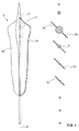
- FIGS. 1 to 3 Lichtumlenk Scheme 3 of an inventive light guide are shown.
- the FIG. 4 shows a component with an inventive optical fiber 1. Both in the FIGS. 1 to 3 as well as at the FIG. 4 each is a schematic illustration.
- FIGS. 5 and 6 microscopic sectional views of a real light guide 1 according to the invention are shown, wherein a plurality of light deflection structures 3 can be seen in each case.
- FIGS. 1 and 2 a single light redirecting structure 3 is shown.
- On the left side of the FIG. 1 2 shows a side view of the light deflection structure 3, and cross-sectional views in planes perpendicular thereto are shown on the right side at the respective corresponding heights.
- the three-dimensional shape of the Lichtumlenk Vietnamese 3 is particularly in the FIG. 1 thus easily recognizable.
- the Lichtumlenk Weg 3 has a rod-shaped, elongated and one-piece base body 4, which is formed substantially rotationally symmetrical and thereby defines a longitudinal axis 6 of the base body 4 and the Lichtumlenk Scheme 3, which coincides with the axis of symmetry of the base body 4.
- the main body 4 has, except in the region of a thickening 5 along its entire longitudinal extension to a substantially constant thickness.
- the thickening 5 is arranged at 15-35% of the total longitudinal extension of the main body 4.
- each of the lugs 7a and 7b has a flat, substantially quadrangular shape and is accordingly bounded by four outer sides, one of which is connected to the main body 4 along its entire length.
- the These upper and lower sides adjoining the base body 4 each extend perpendicular to the longitudinal axis 6 of the base body 4 outwards and slightly obliquely toward one another.
- the thickness of the lugs 7a, 7b which in each case extend as a whole along a flat surface, is many times smaller than the side lengths of the lugs 7a, 7b.
- the lugs 7a, 7b each have an overall substantially constant thickness.
- the two lugs 7a and 7b are arranged at the same height and extend with their sides connected to the base 4 over 1/3 to 2/3 of the total longitudinal extension of the base body 4th
- three light deflecting structures 3, 3 ', 3 " which in the present case are all formed in one piece, are provided, which are provided in an optical waveguide according to the invention
- the three light deflecting structures 3, 3', 3" extend with their Longitudinal axes 6 parallel to each other and are arranged at the same height in the light guide.
- the maximum diameter d is measured perpendicular to the longitudinal axis 6. In the areas outside the thickening 5, the diameter of the base body 4 is half as large or even smaller.
- a center M1, M2 or M3 of the thickening 5 is defined in each case.
- the thickening 5 forms in each case a circular surface, which in the FIG. 3 each indicated by a dashed line.
- the FIG. 4 shows above a component with a light guide 1 and a cover layer 8, which is attached to a light output surface 2 of the light guide 1 and this completely covers.
- the cover layer 8 may be injection-molded onto the light guide 1 and made of a different material than the light guide 1.
- the component can thus be produced in particular by two-component injection molding, wherein the material of the light guide 1 forms the first and that of the cover layer 8 forms the second component.
- the cover layer 8 may also be a film or a coating, for example.
- the cover layer 8 can form a protection of the light guide 1 against external influences.
- the cover layer 8 may also have a coloration to allow the emission of colored light.
- the cover layer 8 has the function of a diffuser to effect a diffuse light emission and / or to reduce the visibility of the Lichtumschtechnik GmbH 3.
- the cover layer 8 is transparent.
- a laser 9 is used for producing the plurality of light deflection structures 3 which are arranged at regular intervals and parallel to one another in the light guide 1 and which in the present case are all formed in one piece.
- 9 laser light is emitted from the laser to enter energy into the interior of the light guide 1 and thereby to the desired locations to cause the formation of Lichtumlenk Weg 3. Due to the energy input, the optical fiber material is locally melted and then cooled again.
- the production of the Lichtumlenk Modellen 3 can be done before attaching the cover layer 8 at the light guide 1 or the laser light can, as in the FIG. 4 shown are irradiated through the cover layer 8 in the light guide 1.
- the laser light is in accordance with FIG. 4 irradiated in the light guide 1, that the laser beam penetrates perpendicular to the light output surface 2 in the light guide 1.
- the light from one or more light sources 10 is preferably radiated laterally into the light guide 1, that is to say that it strikes the light deflection structures 3 from a direction approximately perpendicular to the longitudinal axes 6.
- one or more light sources may also be embedded in the light guide 1.
- the light source or sources 10 may be, in particular, LED light sources.
- the Lichtumlenk Weg 3 are preferably each formed the same and preferably arranged at regular intervals to each other.
- the Lichtumlenk Weg 1 can be arranged in accordance with irregular intervals to each other in the light guide 1. However, they can also be arranged at regular intervals, that is to say in a regular grid, and geometrically differently configured and / or dimensioned in order to achieve the desired varying brightness distribution.
- the light deflecting structures 3 can have different lengths and thicknesses of their thickenings 5, which can be easily achieved by different energy inputs by means of the laser 9.
- the Lichtumlenk Weg Technology Inc., the Lichtumlenk Scheme 3 can also be made such that they have different numbers of flags 7a, 7b.
- the Lichtumlenk Scheme 3 can also at different heights and / or in be arranged in different orientations in the light guide 1.
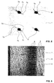
- FIGS. 5 and 6 show microscopic photographs of a real manufactured, inventive light guide.
- Lichtumlenk Weg 3 which are all formed in one piece in the present case, a green laser manufacturer Coherent GmbH, 64807 Dieburg, Germany, was used. It was the model Hyperrapid 25, which has a maximum output power of 25 W (watts).
- the pulse duration of the laser pulses was 10 ps (picoseconds) and the wavelength was 532 nm. It was focused by means of a 100 mm optics, which corresponds to a spot diameter of about 10 ⁇ m.
- the green laser was operated with a power of about 5W (watt).
- FIGS. 5 and 6 a plurality of Lichtumlenk Cooken 3 could be generated in this way.
- the in the FIGS. 5 and 6 each have a similar configuration as those of FIGS. 1 to 4 on.
- the Lichtumlenk Cook 3 of FIGS. 1 to 4 have the actually generated Lichtumlenk Modellen 3 of FIGS. 5 and 6 more than two flags each.
- At least two of the three lugs 7a, 7b and 7c are arranged on mutually substantially diametrically opposite sides of the main body 4 and thereby cause a particularly large surface which determines the light deflection.
- each of the thickenings 5 of the base body 4 of the Lichtumlenk Scheme 3 are visible.
- the cross-sectional areas of the thickenings 5 perpendicular to the longitudinal axes 6 are visible. It is easy to see that these cross-sectional areas are each formed circular, that is, surrounded by an outer boundary line, which at least approximately forms a circle.
- light guide 1 is polymethyl methacrylate (PMMA), in particular Plexiglas ® 8N Evonik Industries AG (Kirschenallee, 64293 Darmstadt).
- PMMA polymethyl methacrylate
- Plexiglas ® 8N Evonik Industries AG Plexiglas ® 8N Evonik Industries AG (Kirschenallee, 64293 Darmstadt).
- FIG. 7 shows a further possible embodiment of a Lichtumlenk Scheme 3 of an inventive optical fiber 1.
- the optical fiber 1 can Lichtumlenk Cooken corresponding to that in the FIG. 1 shown or according to the in the FIG. 7 have shown embodiment. Of course, it can also have different Lichtumlenk Cooken 3, ie of both embodiments.
- the in the FIG. 7 shown Lichtumlenk Cook 3 has in contrast to that of FIG. 1 a two-part base body 4 with two spaced-apart parts, which are connected to each other via two flags e, f.
- the Lichtumlenk Cook 3 of FIG. 7 has an upper region in which the first part of the base body 4 is arranged. At this first part of the main body 4, which forms a thickening 5, four flags a, b, c, d are attached.
- the four lugs a, b, c, d extend only in the upper area of the Lichtumlenk Cook 3.
- a central region of the Lichtumlenk Cook 3 has two flags e, f, which are connected at their upper and lower ends in each case, but spaced therebetween run.
- the Lichtumlenk Scheme also has a lower portion, which is formed by a second part of the base body 4 without flags attached thereto. The first and the second part of the base body 4 are thus spaced from each other.
Landscapes
- Physics & Mathematics (AREA)
- Engineering & Computer Science (AREA)
- General Physics & Mathematics (AREA)
- Optics & Photonics (AREA)
- Manufacturing & Machinery (AREA)
- Health & Medical Sciences (AREA)
- Ophthalmology & Optometry (AREA)
- Mechanical Engineering (AREA)
- Microelectronics & Electronic Packaging (AREA)
- Light Guides In General And Applications Therefor (AREA)
- Planar Illumination Modules (AREA)
Abstract
Es wird ein Lichtleiter (1) angegeben, welcher eine Vielzahl von Lichtumlenkstrukturen (3) aufweist, die im Inneren des Lichtleiters (1) angeordnet sind. Die Lichtumlenkstrukturen (3) weisen jeweils einen langgestreckten Grundkörper (4) auf, welcher entlang seiner Längsrichtung um ein Vielfaches grösser dimensioniert ist als in die senkrecht zu dieser Längsrichtung stehenden Richtungen.A light guide (1) is provided, which has a plurality of light deflection structures (3) which are arranged in the interior of the light guide (1). The Lichtumlenkstrukturen (3) each have an elongated base body (4), which is dimensioned along its longitudinal direction by a multiple greater than in the perpendicular to this longitudinal direction directions.
Description
Die vorliegende Erfindung betrifft einen Lichtleiter, welcher eine Vielzahl von Lichtumlenkstrukturen aufweist. Derartige Lichtleiter werden in verschiedenen Anwendungsgebieten und insbesondere im Automobilbau zum Beispiel zur Herstellung eines beleuchtbaren Anzeige- oder Dekorelements verwendet.The present invention relates to a light guide having a plurality of Lichtumlenkstrukturen. Such light guides are used in various fields of application and in particular in the automotive industry, for example for producing an illuminable display or decorative element.
Lichtleiter dienen zum Transportieren von Licht und werden in den unterschiedlichsten Anwendungsgebieten verwendet. Der Lichtleiter leitet die von einer Lichtquelle ausgestrahlten Lichtstrahlen, welche zum Beispiel über eine Lichteinkoppelfläche in den Lichtleiter eingekoppelt werden, in seinem Inneren zu einer Lichtauskoppelfläche, über welche die Lichtstrahlen den Lichtleiter verlassen. Die Lichtstrahlen können den Lichtleiter dabei diffus in verschiedene Richtungen oder gezielt in eine bestimmte Richtung, zum Beispiel in Richtung eines Betrachters, verlassen, um eine entsprechend gewünschte Lichtwirkung zu erzielen.Light guides are used to carry light and are used in a wide variety of applications. The optical waveguide passes the light beams emitted by a light source, which are coupled into the optical waveguide, for example via a light coupling surface, in its interior to form a light decoupling surface, via which the light beams leave the optical waveguide. The light beams can leave the light guide diffusely in different directions or deliberately in a certain direction, for example in the direction of an observer, in order to achieve a correspondingly desired light effect.
Ein Anwendungsgebiet von Lichtleitern findet sich insbesondere im Automobilbau. So ist es bei Kraftfahrzeugen bekannt, im Innen- oder Aussenraum befindliche Bedien- und Betätigungselemente mit Anzeige- und Ausleuchtelementen zu versehen, die via einen Lichtleiter von einer dahinter angeordneten Lichtquelle beleuchtet werden, um die Erkennbarkeit der einzelnen Bedien- und Betätigungselemente insbesondere auch bei Nacht zu gewährleisten. Auch werden oft hinterleuchtbare und entsprechend mit einem Lichtleiter versehene Dekorelemente und Zierleisten verwendet, um zum Beispiel in Form einer Türeinstiegsleiste auf den Markennamen des Kraftfahrzeugs hinzuweisen, oder um einen speziellen Effekt zu bewirken und dabei die Wahrnehmung des Betrachters auf sich zu ziehen. Der Lichtleiter kann somit insbesondere dazu dienen, eine gleichmässige Ausleuchtung des bzw. der Anzeige- oder Dekorelemente zu erreichen.An application of optical fibers is found in particular in the automotive industry. Thus, it is known in motor vehicles, located in the interior or exterior control and operating elements to be provided with display and illumination elements, which are illuminated via a light guide from a light source behind it, the visibility of the individual controls and actuators especially at night to ensure. Also, often backlit and appropriately provided with a light guide decorative elements and moldings are used to indicate, for example in the form of a door sill strip on the brand name of the motor vehicle, or order to create a special effect and thereby attract the viewer's perception. The light guide can thus serve, in particular, to achieve a uniform illumination of the display element or decoration elements.
Ein anderes Anwendungsgebiet betrifft zum Beispiel die Raumausleuchtung und die Raumbeleuchtung. Lichtleiter werden hier in Leuchten verwendet, um eine bestimmte gewünschte Abstrahlung des von einer oder mehreren Lichtquellen ausgestrahlten Lichts zu erreichen. Je nach Anwendung kann die gewünscht Abstrahlung gezielt und insbesondere fokussiert in eine bestimmte Richtung erfolgen oder diffus in unterschiedliche Richtungen.Another field of application relates, for example, to room illumination and room lighting. Optical fibers are used here in luminaires to achieve a certain desired radiation of the light emitted by one or more light sources. Depending on the application, the desired radiation can be targeted and in particular focused in a certain direction or diffused in different directions.
Um die Lichtstrahlen möglichst gleichmässig und verlustfrei zu einer Lichtauskoppelfläche zu leiten, wird in der
In der
Es ist eine Aufgabe der vorliegenden Erfindung, einen bzgl. Beschädigungen unempfindlichen Lichtleiter anzugeben, welcher eine effiziente und einfach einstellbare Lichtauskopplung ermöglicht.It is an object of the present invention to provide a damage-insensitive light guide, which enables an efficient and easily adjustable light extraction.
Zur Lösung dieser Aufgabe wird ein Lichtleiter vorgeschlagen, wie er in Anspruch 1 angegeben ist. Vorteilhafte Ausgestaltungen der Erfindung sind in den abhängigen Ansprüchen angegeben.To solve this problem, a light guide is proposed, as indicated in
Die vorliegende Erfindung stellt also einen Lichtleiter zur Verfügung mit einer Vielzahl von Lichtumlenkstrukturen, die im Inneren des Lichtleiters angeordnet sind. Die Lichtumlenkstrukturen weisen jeweils einen langgestreckten Grundkörper auf, welcher entlang seiner Längsrichtung um ein Vielfaches grösser dimensioniert ist als in die senkrecht zu dieser Längsrichtung stehenden Richtungen.The present invention thus provides a light guide with a plurality of Lichtumlenkstrukturen which are arranged in the interior of the light guide. The Lichtumlenkstrukturen each have an elongated body, which is dimensioned along its longitudinal direction by a multiple greater than in the perpendicular to this longitudinal direction directions.
Es hat sich gezeigt, dass Lichtstrahlen, welche insbesondere seitlich, das heisst aus einer im Wesentlichen senkrecht zur Längsrichtung der Lichtumlenkstrukturen stehenden Richtung, auf eine der Lichtumlenkstrukturen auftreffen, eine Umlenkung zur Längsrichtung der Lichtumlenkstruktur hin erfahren. Konkret wird das Licht dabei jeweils zur Längsachse des Grundkörpers hin umgelenkt, welche sich zentral in Längsrichtung durch den Grundkörper hindurch erstreckt.It has been found that light rays, which impinge on one of the light deflection structures in particular laterally, that is to say from a direction substantially perpendicular to the longitudinal direction of the light deflection structures, undergo a deflection towards the longitudinal direction of the light deflection structure. Specifically, the light is deflected in each case toward the longitudinal axis of the main body, which extends centrally in the longitudinal direction through the base body.
Durch das Vorsehen einer Vielzahl von derartigen Lichtumlenkstrukturen in einem Lichtleiter kann somit eine gezielte Lichtumlenkung des in den Lichtleiter eingestrahlten Lichts in eine oder mehrere bestimmte Richtungen erreicht werden. Das Licht kann dadurch in eine oder mehrere einstellbare Richtungen aus dem Lichtleiter ausgekoppelt werden. Je nach Ausrichtung und Lage der Lichtumlenkstrukturen kann die Lichtauskopplung derart eingestellt werden, dass sie zum Beispiel fokussiert aus dem Lichtleiter in eine bestimmte Richtung oder diffus in einen bestimmten Richtungsbereich erfolgt.By providing a plurality of such Lichtumlenkstrukturen in a light guide thus targeted light deflection of the light irradiated in the light guide light can be achieved in one or more specific directions. The light can thereby be coupled out in one or more adjustable directions from the light guide. Depending on the orientation and position of the Lichtumlenkstrukturen the light extraction can be adjusted such that it takes place, for example, focused from the light guide in a particular direction or diffused in a certain direction range.
Der Grundkörper der Lichtumlenkstrukturen ist vorteilhaft stabförmig ausgebildet. Entlang seiner Längsrichtung ist der Grundkörper somit um ein Vielfaches grösser dimensioniert als in alle senkrecht zu dieser Längsrichtung stehenden Richtungen. Vorteilhaft ist er um einen Faktor von zumindest 3, vorteilhafter von zumindest 5 und noch vorteilhafter von zumindest 10 entlang seiner Längsrichtung grösser bemessen als in die an irgendeiner Stelle entlang seiner Längserstreckung senkrecht dazu stehenden Richtungen. Es wurde festgestellt, dass die Lichtauskoppelung, insbesondere die gezielte Lichtauskopplung, aus dem Lichtleiter je effizienter wird, desto langgestreckter die Grundkörper der Lichtumlenkstrukturen sind.The main body of the Lichtumlenkstrukturen is advantageously formed rod-shaped. Along its longitudinal direction, the basic body is thus dimensioned larger by a multiple than in all directions perpendicular to this longitudinal direction. Advantageously, it is dimensioned larger by a factor of at least 3, more advantageously of at least 5 and more advantageously of at least 10 along its longitudinal direction than in the directions perpendicular thereto at any point along its longitudinal extent. It has been found that the light extraction, in particular the targeted light extraction, from the light guide is the more efficient, the elongated are the main body of Lichtumlenkstrukturen.
Da die Lichtumlenkstrukturen im Inneren des Lichtleiters angeordnet sind, hat eine Beschädigung der Lichtleiteroberfläche keinen oder kaum einen Einfluss auf die Funktion des Lichtleiters, was dessen Lichtabstrahlcharakteristik angeht. Vorteilhaft sind die Lichtumlenkstrukturen dabei vollständig im Inneren des Lichtleiters angeordnet, das heisst komplett vom Material des Lichtleiters umgeben.Since the Lichtumlenkstrukturen are arranged in the interior of the light guide, damage to the light guide surface has little or no effect on the function of the light guide, as far as its Lichtabstrahlcharakteristik. Advantageously, the Lichtumlenkstrukturen be completely disposed in the interior of the light guide, that is completely surrounded by the material of the light guide.
Vorzugsweise sind die Lichtumlenkstrukturen durch eine lokale Materialveränderung, insbesondere durch eine Aufschmelzung des Materials, des Lichtleiters hergestellt. Das Material des Lichtleiters wird zur Herstellung der Lichtumlenkstrukturen also vorzugsweise an den entsprechenden Stellen mittels Wärmeeinwirkung aufgeschmolzen und wieder abgekühlt. Es wird dadurch an den jeweiligen Stellen eine lokale Strukturveränderung des Lichtleitermaterials bewirkt, wodurch die Lichtumlenkstrukturen gebildet werden. Das Material des Lichtleiters wird vorzugsweise bei der Herstellung der Lichtumlenkstrukturen aber nicht karbonisiert.The light deflection structures are preferably produced by a local material change, in particular by melting of the material, of the light guide. The material of the optical waveguide is therefore preferably melted at the corresponding points by means of heat for the production of Lichtumlenkstrukturen and cooled again. It is thereby effected at the respective locations a local structural change of the optical fiber material, whereby the Lichtumlenkstrukturen are formed. However, the material of the light guide is preferably not carbonized in the manufacture of the light redirecting structures.
Beim Material des Lichtleiters handelt es sich bevorzugt um Kunststoff, Glas oder um ein Elastomer. Vorzugsweise ist der Lichtleiter zudem aus einem transparenten Material hergestellt. Es kann sich beim Kunststoff beispielsweise um Polymethylmethacrylat (PMMA), Polycarbonat (PC) oder Polymethacrylmethylimid (PMMI) handeln. Beim Elastomer kann es sich beispielsweise um Silikon handeln.The material of the light guide is preferably plastic, glass or an elastomer. Preferably, the light guide is also made of a transparent material. The plastic may be, for example, polymethyl methacrylate (PMMA), polycarbonate (PC) or polymethacrylmethyl imide (PMMI). The elastomer may be, for example, silicone.
Vorzugsweise sind die Lichtumlenkstrukturen mittels eines Lasers hergestellt. Das Laserlicht bewirkt in diesem Fall an den entsprechenden Stellen im Lichtleiter jeweils bevorzugt einen lokalen Wärmeeintrag, welcher zu einer Materialaufschmelzung führt. Die Herstellung der Lichtumlenkstrukturen mittels eines Lasers ist nicht nur besonders einfach, sondern kann auch einfach derart durchgeführt werden, dass die erwähnten langgestreckten Grundkörper sowie die nachstehend angegebenen lokalen Verdickungen und Fahnen entstehen. Bei der Herstellung der Lichtumlenkstrukturen mittels eines Lasers kann gewährleistet werden, dass das Material zwar lokal aufgeschmolzen, nicht aber karbonisiert wird. Selbstverständlich können die Lichtumlenkstrukturen aber auch mittels beliebiger anderer, dem Fachmann bekannten Verfahren hergestellt werden.Preferably, the Lichtumlenkstrukturen are made by means of a laser. In this case, the laser light in each case preferably effects a local heat input at the corresponding points in the optical waveguide, which leads to a material melting. The production of Lichtumlenkstrukturen by means of a laser is not only particularly simple, but can also be carried out simply such that the mentioned elongated body and the local thickening and flags given below arise. In the production of Lichtumlenkstrukturen by means of a laser can be ensured that the material is locally melted, but not carbonized. Of course, the Lichtumlenkstrukturen but also by any other methods known in the art can be produced.
Die vorliegende Erfindung bezieht sich somit ausserdem auf ein Verfahren zur Herstellung eines Lichtleiters, der wie angegeben ausgebildet ist. Dabei wird der Lichtleiter mit einem Laser bestrahlt, um im Inneren des Lichtleiters eine Vielzahl von Lichtumlenkstrukturen mit jeweils einem langgestreckten Grundkörper auszubilden.The present invention thus also relates to a process for the preparation a light guide, which is formed as indicated. In this case, the light guide is irradiated with a laser to form a plurality of Lichtumlenkstrukturen, each with an elongated body in the interior of the light guide.
Um eine optimale Form der Lichtumlenkstrukturen zu erreichen, werden diese bevorzugt mit Hilfe von grünem Laserlicht hergestellt. Vorzugweise weist das grüne Laserlicht eine Wellenlänge im Bereich von 490 nm - 575 nm auf. Vorteilhaft wird ein Ultrakurzpulslaser, bevorzugter ein Femtosekundenlaser oder ein Pikosekundenlaser, verwendet.In order to achieve an optimum shape of the Lichtumlenkstrukturen, they are preferably made using green laser light. Preferably, the green laser light has a wavelength in the range of 490 nm - 575 nm. Advantageously, an ultrashort pulse laser, more preferably a femtosecond laser or a picosecond laser, is used.
Bevorzugt ist der Grundkörper der Lichtumlenkstrukturen jeweils im Wesentlichen rotationssymmetrisch, insbesondere vollständig rotationssymmetrisch. Die Lichtumlenkstrukturen sind dadurch einfacher herstellbar, und die durch die Lichtumlenkstrukturen bewirkte Lichtumlenkung ist einfacher vorausrechenbar. Es kann insbesondere eine Leuchtdichtesimulationssoftware erstellt werden, um die Leuchtdichte an der Oberfläche und insbesondere an der Lichtauskoppelfläche des Lichtleiters vorauszuberechnen, bzw. um umgekehrt dazu ausgehend von einer gewünschten Oberflächenleuchtdichte die Anordnung und/oder Ausbildung der Lichtumlenkstrukturen innerhalb des Lichtleiters zu bestimmen. Auf diese Art und Weise kann sehr einfach eine beliebige gewünschte Leuchtdichteverteilung an der Lichtleiteroberfläche erzielt werden. Durch die Rotationssymmetrie des Grundkörpers ist die Längsachse der jeweiligen Lichtumlenkstruktur bestimmt, welche mit der Symmetrieachse übereinstimmt.Preferably, the main body of the Lichtumlenkstrukturen is each substantially rotationally symmetric, in particular completely rotationally symmetrical. The Lichtumlenkstrukturen are thus easier to manufacture, and caused by the Lichtumlenkstrukturen light deflection is easier vorausrechbar. In particular, a luminance simulation software can be created in order to predict the luminance at the surface and in particular at the light outcoupling surface of the light guide, or vice versa, starting from a desired surface luminance to determine the arrangement and / or formation of the Lichtumlenkstrukturen within the light guide. In this way, it is very easy to achieve any desired luminance distribution on the optical waveguide surface. Due to the rotational symmetry of the base body, the longitudinal axis of the respective Lichtumlenkstruktur is determined, which coincides with the axis of symmetry.
Unter dem Begriff "Leuchtdichte" wird das Verhältnis der Lichtstärke zur Grösse der sichtbaren leuchtenden Lichtauskoppelfläche verstanden, welche in Candela pro Quadratmeter der Lichtauskoppelfläche (cd/m2) angegeben wird.The term "luminance" is understood to mean the ratio of the luminous intensity to the size of the visible luminous light output surface, which is given in candelas per square meter of the light outcoupling surface (cd / m 2 ).
In einer insbesondere bevorzugten Ausführungsform weist zumindest ein Grundkörper entlang seiner Längsrichtung eine lokale Verdickung auf, bevorzugt weisen sämtliche Grundkörper entlang ihrer Längsrichtung jeweils eine lokale Verdickung auf. Die lokale Verdickung ist entlang der Längsrichtung des Grundkörpers bevorzugt jeweils dezentral im Grundkörper angeordnet, das heisst nicht genau in der Mitte des Grundkörpers. Es hat sich gezeigt, dass ein überwiegender Grossteil der seitlich auf die Lichtumlenkstruktur einfallenden Lichtstrahlen in Richtung zur Längsachse des Grundkörpers hin umgelenkt wird.In a particularly preferred embodiment, at least one base body has a local thickening along its longitudinal direction, and all the base bodies preferably have a local thickening along their longitudinal direction. The local thickening is preferably arranged decentralized in the main body along the longitudinal direction of the main body, that is not exactly in the middle of the main body. It has been shown that a major part of the side to the Lichtumlenkstruktur incident light rays in the direction of the longitudinal axis of the body is deflected out.
Die Verdickung weist bevorzugt senkrecht zur Längsachse des Grundkörpers einen kreisförmigen Querschnitt auf. Bevorzugt ist die Verdickung in Bezug auf die Längsrichtung des Grundkörpers bei 15 - 35 % der gesamten Längserstreckung des Grundkörpers angeordnet. Der Durchmesser der Verdickung, gemessen in eine senkrecht zur Längsachse des Grundkörpers stehende Richtung, ist bevorzugt nicht grösser als 30 µm.The thickening preferably has a circular cross-section perpendicular to the longitudinal axis of the main body. Preferably, the thickening with respect to the longitudinal direction of the base body is arranged at 15-35% of the total longitudinal extent of the base body. The diameter of the thickening, measured in a direction perpendicular to the longitudinal axis of the base body, is preferably not greater than 30 microns.
Vorteilhaft erstrecken sich die Grundkörper der Lichtumlenkstrukturen entlang ihrer jeweiligen Längsrichtung im Wesentlichen parallel, bevorzugt vollständig parallel zueinander. Es kann dadurch beispielsweise erreicht werden, dass das in den Lichtleiter eingestrahlte Licht zu einem überwiegenden Grossteil aus zwei zueinander gegenüberliegenden, bevorzugt ebenen Aussenflächen des Lichtleiters ausgekoppelt wird.Advantageously, the main bodies of the light deflecting structures extend substantially parallel along their respective longitudinal direction, preferably completely parallel to one another. It can thereby be achieved, for example, that the light irradiated into the light guide is coupled to a predominant majority of two mutually opposite, preferably flat outer surfaces of the light guide.
In einer bevorzugten Ausführungsform weist zumindest eine Lichtumlenkstruktur zumindest eine, insbesondere zwei oder mehr als zwei Fahnen auf, welche am Grundkörper angebracht sind, bevorzugt weisen sämtliche Lichtumlenkstrukturen jeweils zumindest eine, insbesondere zwei oder mehr als zwei Fahnen auf, welche am Grundkörper angebracht sind. Der Ausdruck Fahne bezieht sich auf die Form der Lichtumlenkstrukturen und ist zu verstehen als ein an der Grundstruktur angebrachter lappenförmiger Teil. Die Fahne bzw. Fahnen haben bevorzugt insgesamt eine annähernd viereckige Form, wobei sie sich vorwiegend entlang von zwei Dimensionen in einer Fläche erstrecken, welche insbesondere eben sein kann. In die dritte, zu dieser Fläche senkrecht stehende Dimension weist die zumindest eine Fahne in der Regel eine Dicke auf, welche im Vergleich zu den Seitenlängen der Fahne in der Fläche entlang der ersten beiden Dimensionen um ein Vielfaches kleiner dimensioniert ist. Bevorzug ist die zumindest eine Fahne höchstens 5 µm dick. Bevorzugt ist die zumindest eine Fahne entlang einer ihrer vier Seiten, insbesondere entlang einer gesamten Seitenlänge, mit dem Grundkörper verbunden.In a preferred embodiment, at least one Lichtumlenkstruktur at least one, in particular two or more than two lugs, which are attached to the body, preferably all Lichtumlenkstrukturen each have at least one, in particular two or more than two flags, which are attached to the base body. The term flag refers to the shape of the Lichtumlenkstrukturen and is to be understood as an attached to the basic structure flap-shaped part. The flag or flags preferably have an overall approximately quadrangular shape, wherein they extend predominantly along two dimensions in a surface, which may be particularly flat. In the third, perpendicular to this surface dimension, the at least one flag usually has a thickness which is dimensioned smaller compared to the side lengths of the flag in the surface along the first two dimensions by a multiple. Preferably, the at least one flag is at most 5 μm thick. Preferably, the at least one flag along one of its four sides, in particular along an entire side length, connected to the main body.
Durch das Vorsehen der Fahne bzw. der Fahnen kann die für die Lichtumlenkung relevante Fläche der Lichtumlenkstruktur wesentlich vergrössert werden, so dass pro Lichtumlenkstruktur erheblich mehr Licht umgelenkt werden kann. Die Fahne(n) dienen also dazu, die Effizienz der Lichtumlenkung zu verbessern.By providing the flag or the flags relevant for the light deflection Surface of Lichtumlenkstruktur be significantly increased so that significantly more light can be deflected per Lichtumlenkstruktur. The flag (s) thus serve to improve the efficiency of the light deflection.
Vorteilhaft erstreckt sich zumindest eine Fahne der zumindest einen Fahne über 1/3 bis 2/3 der gesamten Längserstreckung des Grundkörpers. Die zumindest eine Fahne kann dabei insbesondere entlang einer ihrer Seiten über einen Bereich von 1/3 bis 2/3 der gesamten Längserstreckung des Grundkörpers mit diesem verbunden sein. Die Breite der Fahne, gemessen in eine senkrecht zur Längsachse des Grundkörpers stehende Richtung, beträgt bevorzugt höchstens 30 µm.Advantageously, at least one lug of the at least one lug extends over 1/3 to 2/3 of the total longitudinal extent of the basic body. The at least one flag may in particular be connected along one of its sides over a range of 1/3 to 2/3 of the total longitudinal extent of the main body with this. The width of the flag, measured in a direction perpendicular to the longitudinal axis of the base body, is preferably at most 30 microns.
Vorteilhaft ist der Grundkörper einteilig oder mehrteilig, bevorzugt einteilig ausgebildet. Falls der Grundkörper mehrteilig ausgebildet ist, so ist der Grundkörper bevorzugt wenigstens zweiteilig aufgebaut. Falls der Grundkörper wenigstens zweiteilig aufgebaut ist, so sind die wenigstens zwei Teile des Grundkörpers bevorzugt voneinander beabstandet. Bevorzugt sind die wenigstens zwei Teile mittels wenigstens einer Fahne miteinander verbunden. Die Lichtumlenkstrukturen sind vorteilhaft jedoch jeweils als Ganzes einteilig ausgebildet, das heisst sie weisen keine voneinander beabstandeten Teile auf, die nicht durch ein anderes Teil derselben Lichtumlenkstruktur miteinander verbunden sind.Advantageously, the main body is in one or more parts, preferably formed in one piece. If the base body is designed in several parts, the base body is preferably constructed in at least two parts. If the base body is constructed at least in two parts, the at least two parts of the base body are preferably spaced apart from one another. Preferably, the at least two parts are connected to each other by means of at least one flag. The Lichtumlenkstrukturen are advantageous, however, each formed integrally as a whole, that is, they have no spaced-apart parts that are not connected to each other by another part of the same Lichtumlenkstruktur.
Bevorzugt, um eine besonders grosse, für die Lichtumlenkung relevante Fläche zu erreichen, sind jeweils zumindest zwei Fahnen am Grundkörper angebracht. Um die Oberfläche der Lichtumlenkstruktur im Hinblick auf die Lichtumlenkung zu maximieren, sind die beiden Fahnen vorteilhaft auf im Wesentlichen diametral einander gegenüberliegenden Seiten am Grundkörper angebracht und erstrecken sich insbesondere in einander entgegengesetzte radiale Richtungen vom Grundkörper weg.Preferably, in order to achieve a particularly large, relevant for the light deflection surface, at least two flags are attached to the main body. In order to maximize the surface of the Lichtumlenkstruktur with respect to the light deflection, the two flags are advantageously mounted on substantially diametrically opposite sides of the base body and extending in particular in opposite radial directions away from the body.
Der Lichtleiter weist bevorzugt eine Lichtauskoppelfläche auf, über welche das in den Lichtleiter von einer Lichtquelle eingestrahlte Licht nach aussen hin abgestrahlt wird. Vorzugsweise stehen die Grundkörper der Lichtumlenkstrukturen mit ihren Längsrichtungen, das heisst Längsachsen, jeweils im Wesentlichen senkrecht zu dieser Lichtauskoppelfläche.The light guide preferably has a light outcoupling surface, via which the light radiated into the light guide by a light source is radiated outwards. Preferably, the main bodies of the light deflecting structures are in each case substantially perpendicular to this light outcoupling surface with their longitudinal directions, that is to say longitudinal axes.
Um eine gute Ausleuchtung erreichen zu können, weisen die Grundkörper der Lichtumlenkstrukturen bevorzugt jeweils eine Längserstreckung von mindestens 100 µm, noch bevorzugter von mindestens 300 µm, auf. Vorteilhaft sind die Lichtumlenkstrukturen bzw. deren Grundkörper jedoch höchstens 800 µm lang. Lichtumlenkstrukturen, welche eine grössere Längserstreckung aufweisen, werden für das menschliche Auge sichtbar, was in den meisten Fällen nicht erwünscht ist. Bzgl. der Sichtbarkeit für das menschliche Auge wird hier sowie nachstehend jeweils von einem Abstand von ca. 30 cm - 70 cm von der Lichtauskoppelfläche ausgegangen. Unsichtbar sind die Lichtumlenkstrukturen dann, wenn im unbeleuchteten Zustand der Bereich des Lichtleiters mit den Lichtumlenkstrukturen aus einer solchen Distanz für einen Betrachter kaum von einem Bereich des Lichtleiters unterscheidbar ist, der keine Lichtumlenkstrukturen aufweist. Insbesondere sind die einzelnen Lichtumlenkstrukturen dann kaum zu erkennen.In order to be able to achieve good illumination, the main bodies of the light deflecting structures preferably each have a longitudinal extent of at least 100 μm, more preferably of at least 300 μm. However, the Lichtumlenkstrukturen or their body are advantageously at most 800 microns long. Lichtumlenkstrukturen which have a greater longitudinal extent are visible to the human eye, which is not desirable in most cases. Concerning. The visibility for the human eye is assumed here and below in each case by a distance of about 30 cm - 70 cm from the light output surface. The light deflecting structures are invisible when, in the unlit state, the region of the optical waveguide with the light deflecting structures can hardly be distinguished from such a distance by a viewer from a region of the optical waveguide which has no light deflecting structures. In particular, the individual Lichtumlenkstrukturen are then hardly recognizable.
Vorteilhaft sind die Lichtumlenkstrukturen in regelmässigen oder unregelmässigen Abständen, bevorzugt in regelmässigen Abständen, zueinander im Lichtleiter angeordnet. Die Abstände zwischen den Lichtumlenkstrukturen betragen bevorzugt jeweils mindestens 50 µm, bevorzugter jeweils mindestens 80 µm, insbesondere mindestens 100 µm. Je grösser die Abstände zwischen den einzelnen Lichtumlenkstrukturen sind, desto schwerer sind sie von Auge im unbeleuchteten Zustand des Lichtleiters im Lichtleiter erkennbar. Bei Abständen von weniger als 50 µm sind die Strukturen unabhängig von der eingesetzten Laserenergie zu deren Herstellung sichtbar. Um eine ausreichende Lichtumlenkung und somit Ausleuchtung im Bereich der Lichtauskoppelfläche zu gewährleisten, sollten die Lichtumlenkstrukturen jedoch Abstände zwischen einander von bevorzugt höchstens 400 µm, bevorzugter von höchstens 200 µm, insbesondere von höchstens 150 µm haben.Advantageously, the Lichtumlenkstrukturen at regular or irregular intervals, preferably at regular intervals, each other in the light guide. The distances between the Lichtumlenkstrukturen are preferably at least 50 .mu.m, more preferably at least 80 .mu.m, in particular at least 100 .mu.m. The greater the distances between the individual Lichtumlenkstrukturen, the harder they are recognizable by eye in the unlit condition of the light guide in the light guide. At distances of less than 50 microns, the structures are visible regardless of the laser energy used for their production. In order to ensure sufficient light deflection and thus illumination in the region of the light coupling-out surface, however, the light deflection structures should have distances between each other of preferably not more than 400 μm, more preferably not more than 200 μm, in particular not more than 150 μm.
Vorteilhaft weist der Grundkörper der Lichtumlenkstrukturen des Lichtleiters senkrecht zur seiner Längsrichtung, insbesondere im Bereich einer allfällig vorhandenen Verdickung des Grundkörpers, eine kreisförmige Querschnittsfläche mit einem Mittelpunkt M auf, wobei ein maximaler Durchmesser d der kreisförmigen Querschnittsfläche des Grundkörpers einer jeweiligen Lichtumlenkstruktur 30 Mikrometer oder weniger beträgt, und wobei der Abstand A zwischen den Mittelpunkten M der kreisförmigen Querschnittsfläche des Grundkörpers der Lichtumlenkstrukturen des Lichtleiters wenigstens 50 Mikrometer beträgt.The main body of the light deflecting structures of the optical waveguide preferably has a circular cross-sectional area with a center M, perpendicular to its longitudinal direction, in particular in the region of any thickening of the main body, wherein a maximum diameter d of the circular cross-sectional area of the main body of a respective Lichtumlenkstruktur is 30 microns or less , and wherein the distance A between the centers M of the circular cross-sectional area of the main body of the Lichtumlenkstrukturen of the light guide at least 50 microns.
Bevorzugt erfüllt der Abstand A folgendes 1. Kriterium:
- Der Abstand A ist grösser als dreimal der maximale Durchmesser d eines Grundkörpers wenigstens einer Lichtumlenkstruktur des Lichtleiters.
- The distance A is greater than three times the maximum diameter d of a base body of at least one Lichtumlenkstruktur the light guide.
Vorteilhaft erfüllt der Abstand A alternativ oder zusätzlich zum 1. Kriterium folgendes 2. Kriterium:
- Der Mittelpunkt der kreisförmigen Querschnittsfläche des Grundkörpers einer jeweiligen Lichtumlenkstruktur des Lichtleiters zum Mittelpunkt der kreisförmigen Querschnittsfläche der Grundkörper sämtlicher weiteren Lichtumlenkstrukturen des Lichtleiters weist einen Abstand A auf, wobei der Abstand A grösser als der maximale Durchmesser d der kreisförmigen Querschnittsfläche des Grundkörpers der jeweiligen Lichtumlenkstruktur geteilt durch den Wert 0.33 ist.
- The center of the circular cross-sectional area of the main body of a respective Lichtumlenkstruktur the light guide to the center of the circular cross-sectional area of the main body of all other Lichtumlenkstrukturen the optical fiber has a distance A, wherein the distance A is greater than the maximum diameter d of the circular cross-sectional area of the main body of the respective Lichtumlenkstruktur divided by the value is 0.33.
Diese vorteilhafte Ausführungsform bietet den Vorteil, dass die Lichtumlenkstrukturen des Lichtleiters im unbeleuchteten Zustand des Lichtleiters von Auge kaum sichtbar sind.This advantageous embodiment has the advantage that the light deflection structures of the light guide are hardly visible to the eye in the unlit state of the light guide.
Besonders vorteilhaft weist der Grundkörper der Lichtumlenkstrukturen senkrecht zur seiner Längsrichtung, insbesondere im Bereich einer allfällig vorhandenen Verdickung des Grundkörpers, eine kreisförmige Querschnittsfläche auf, das heisst eine Querschnittsfläche, welche von einer äusseren Begrenzungslinie umrandet ist, die zumindest annähernd, insbesondere im Wesentlichen einen Kreis bildet. Diese äussere Begrenzungslinie weist insbesondere einen maximalen Durchmesser d auf.Particularly advantageously, the main body of the Lichtumlenkstrukturen perpendicular to its longitudinal direction, in particular in the region of any existing thickening of the body, a circular cross-sectional area, that is, a cross-sectional area which is bordered by an outer boundary line, which forms at least approximately, in particular substantially a circle , This outer boundary line has in particular a maximum diameter d.
Die Lichtumlenkstrukturen können derart im Lichtleiter angeordnet sein, dass das von den Lichtumlenkstrukturen ausgekoppelte Licht als ein Buchstabe, ein Schriftzug, eine Nummer und/oder ein Symbol erscheint. Die Lichtumlenkstrukturen können, um diesen Effekt zu erreichen, entsprechend in der Form eines Buchstabens, eines Schriftzugs, einer Nummer und/oder eines Symbols im Lichtleiter angeordnet sein.The light deflection structures can be arranged in the light guide such that the light coupled out by the light deflection structures appears as a letter, a lettering, a number and / or a symbol. The light redirecting structures may, in order to achieve this effect, be arranged correspondingly in the form of a letter, a lettering, a number and / or a symbol in the light guide.
Gemäss einer Weiterbildung der Erfindung weisen die verschiedenen Lichtumlenkstrukturen unterschiedliche Geometrien, insbesondere unterschiedliche Längserstreckungen, auf, so dass das via die Lichtauskoppelfläche des Lichtleiters ausgekoppelte Licht eine Helligkeitsverteilung aufweist, welche über die Lichtauskoppelfläche variiert. Mit anderen Worten wird die variierende Helligkeitsverteilung aufgrund der unterschiedlichen Geometrien, insbesondere Längserstreckungen der Grundkörper der Lichtumlenkstrukturen bewirkt. Auch unterschiedliche Anzahl von Fahnen und/oder Grössen der Fahnen und/oder der Verdickungen können zu unterschiedlichen Helligkeitswerten führen. Die Lichtumlenkstrukturen können also zum Beispiel insgesamt ein Grauwertbild darstellen und dennoch in regelmässigen Abständen zueinander im gesamten Lichtleiter verteilt sein. Die unterschiedlichen Grauwerte können insbesondere mittels unterschiedlichen Energieeinträgen bei der Herstellung der einzelnen Lichtumlenkstrukturen mittels eines Lasers erreicht werden. Unterschiedliche optische Effekte können aber auch durch das Anordnen der Lichtumlenkstrukturen auf unterschiedlichen Höhen innerhalb des Lichtleiters, durch unterschiedliche Neigungen der Lichtumlenkstrukturen relativ zur Lichtauskoppelfläche des Lichtleiters oder durch regelmässige und/oder unregelmässige Abstände zwischen den Lichtumlenkstrukturen erreicht werden.According to a development of the invention, the different Lichtumlenkstrukturen different geometries, in particular different Longitudinal extents, on, so that the decoupled via the light output surface of the light guide light has a brightness distribution which varies over the light output surface. In other words, the varying brightness distribution is brought about on account of the different geometries, in particular the longitudinal extent of the main bodies of the light deflection structures. Also different number of flags and / or sizes of the flags and / or thickening can lead to different brightness values. The Lichtumlenkstrukturen so for example, a total gray scale image and still be distributed at regular intervals to each other in the entire light guide. The different gray values can be achieved in particular by means of different energy inputs in the production of the individual Lichtumlenkstrukturen by means of a laser. However, different optical effects can also be achieved by arranging the light deflection structures at different heights within the light guide, by different inclinations of the light deflection structures relative to the light output surface of the light guide, or by regular and / or irregular spacing between the light deflection structures.
Der erfindungsgemässe Lichtleiter kann zur Herstellung eines beliebigen Bauteils verwendet werden, welches zusätzlich zum Lichtleiter weitere Elemente aufweisen kann. So kann ein Bauteil zusätzlich zum Lichtleiter zum Beispiel eine Deckschicht aufweisen. Die Deckschicht kann am Lichtleiter angespritzt sein oder beispielsweise als transparente Folie ausgebildet sein, wobei die Deckschicht als Schutz des Lichtleiters gegen äussere Einflüsse dienen kann. Die Deckschicht kann insbesondere koloriert sein, um eine farbige Ausleuchtung zu bewirken. Alternativ oder zusätzlich kann eine Beschichtung am Lichtleiter angebracht sein, um die entsprechenden oder andere Effekte zu erzielen. Das Anbringen einer Beschichtung ist möglich, da die Lichtumlenkstrukturen im Inneren des Lichtleiters angeordnet sind und somit durch das Beschichten nicht beschädigt werden. Auch die Herstellung eines Bauteils mit einem derartigen Lichtleiter im Zweikomponentenspritzguss ist möglich, da die Lichtumlenkstrukturen aufgrund ihrer Anordnung im Inneren des Lichtleiters beim Spritzvorgang nicht beschädigt werden. Das Bauteil kann zusätzlich zum Lichtleiter auch eine mit Durchbrüchen versehene Dekorplatte aufweisen, welche den Lichtleiter abdeckt und aufgrund der Anordnung und Form der Durchbrüche zum Beispiel die Anzeige von Buchstaben, Nummern oder Symbolen bewirken kann. Die Dekorplatte kann insbesondere aus Metall hergestellt sein.The light guide according to the invention can be used to produce any component which may have additional elements in addition to the light guide. Thus, a component in addition to the light guide, for example, have a cover layer. The cover layer may be molded on the light guide or, for example, be formed as a transparent film, wherein the cover layer can serve as protection of the light guide against external influences. The cover layer may in particular be colored to effect a colored illumination. Alternatively or additionally, a coating may be attached to the light guide to achieve the corresponding or other effects. The application of a coating is possible because the Lichtumlenkstrukturen are arranged in the interior of the light guide and thus are not damaged by the coating. The production of a component with such a light guide in the two-component injection molding is possible because the Lichtumlenkstrukturen are not damaged due to their arrangement in the interior of the light guide during the injection process. In addition to the light guide, the component can also have a decorative plate provided with openings, which covers the light guide and, for example, the display of letters, numbers or symbols due to the arrangement and shape of the openings can cause. The decorative plate may in particular be made of metal.
Gemäss einer Weiterbildung der Erfindung ist der erfindungsgemässe Lichtleiter für den Automobilbau vorgesehen. Er kann zur Herstellung eines hinterleuchtbaren Dekorelements, einer Zierleiste und insbesondere zur Herstellung einer Einstiegsleiste verwendet werden.According to one embodiment of the invention, the inventive light guide is provided for the automotive industry. It can be used for producing a backlit decorative element, a decorative strip and in particular for producing a door sill.
Bevorzugte Ausführungsformen der Erfindung werden im Folgenden anhand der Zeichnungen beschrieben, die lediglich zur Erläuterung dienen und nicht einschränkend auszulegen sind. In den Zeichnungen zeigen:
- Fig. 1
- eine Seitenansicht sowie mehrere Querschnittansichten einer schematisch dargestellten Lichtumlenkstruktur mit einteiligem Grundkörper eines erfindungsgemässen Lichtleiters;
- Fig. 2
- eine perspektivische Ansicht von schräg oben der Lichtumlenkstruktur der
Fig. 1 ; - Fig. 3
- eine perspektivische Ansicht von schräg oben von drei schematisch dargestellten Lichtumlenkstrukturen eines erfindungsgemässen Lichtleiters;
- Fig. 4
- eine perspektivische Ansicht eines schematisch dargestellten Bauteils mit einem erfindungsgemässen Lichtleiter sowie mit einem Laser zur Herstellung von Lichtumlenkstrukturen im Lichtleiter und mit einer LED-Lichtquelle zum Einkoppeln von Licht in den Lichtleiter;
- Fig. 5
- eine mikroskopische Schnittansicht eines realen, erfindungsgemässen Lichtleiters, auf der Höhe der Verdickungen der Lichtumlenkstrukturen;
- Fig. 6
- eine mikroskopische Schnittansicht in einer senkrecht zur Schnittansicht der
Fig. 5 stehenden Ebene durch den Lichtleiter derFig. 5 , durch die Grundkörper von mehreren Lichtumlenkstrukturen; sowie - Fig. 7
- eine Seitenansicht einer schematisch dargestellten Lichtumlenkstruktur mit zweiteiligem Grundkörper eines erfindungsgemässen Lichtleiters.
- Fig. 1
- a side view and several cross-sectional views of a schematically illustrated Lichtumlenkstruktur with one-piece body of an inventive optical fiber;
- Fig. 2
- a perspective view obliquely from above the Lichtumlenkstruktur the
Fig. 1 ; - Fig. 3
- a perspective view obliquely from above of three schematically illustrated Lichtumlenkstrukturen a novel optical fiber;
- Fig. 4
- a perspective view of a schematically illustrated component with an inventive optical fiber and with a laser for the production of Lichtumlenkstrukturen in the light guide and with an LED light source for coupling light into the light guide;
- Fig. 5
- a microscopic sectional view of a real, inventive optical fiber, at the height of the thickening of Lichtumlenkstrukturen;
- Fig. 6
- a microscopic sectional view in a direction perpendicular to the sectional view of
Fig. 5 standing plane through the light guide of theFig. 5 , through the main body of several Lichtumlenkstrukturen; such as - Fig. 7
- a side view of a schematically illustrated Lichtumlenkstruktur with two-part main body of an inventive light guide.
In den
In den Figuren sind jeweils Elemente, welche die gleiche oder eine ähnliche Funktion und Wirkung haben, mit denselben Bezugszeichen versehen.In the figures, elements having the same or a similar function and effect are given the same reference numerals.
In den
Die Lichtumlenkstruktur 3 weist einen stabförmigen, langgestreckten und einteiligen Grundkörper 4 auf, welcher im Wesentlichen rotationssymmetrisch ausgebildet ist und dadurch eine Längsachse 6 des Grundkörpers 4 und der Lichtumlenkstruktur 3 definiert, die mit der Symmetrieachse des Grundkörpers 4 übereinstimmt.The
Der Grundkörper 4 weist ausser im Bereich einer Verdickung 5 entlang seiner gesamten Längserstreckung eine im Wesentlichen konstante Dicke auf. Die Verdickung 5 ist bei 15 - 35 % der gesamten Längserstreckung des Grundkörpers 4 angeordnet.The
Am Grundkörper 4 sind auf diametral gegenüberliegenden Seiten zwei Fahnen 7a und 7b angebracht. Die beiden Fahnen 7a und 7b erstrecken sich jeweils in radialer Richtung vom Grundkörper 4 gleich weit nach aussen hin. Jede der Fahnen 7a und 7b hat eine flache, im Wesentlichen viereckige Form und ist dementsprechend von vier Aussenseiten begrenzt, von denen eine entlang ihrer gesamten Länge mit dem Grundkörper 4 verbunden ist. Die an diese mit dem Grundkörper 4 angrenzenden oberen und unteren Seiten erstrecken sich jeweils senkrecht zur Längsachse 6 des Grundkörpers 4 nach aussen und leicht schräg zueinander hin.On the
Die grösste Breite weisen die Fahnen 7a, 7b jeweils in ihrem oberen Bereich auf, welcher ungefähr auf der Höhe der Verdickung 5 angeordnet ist. Nach unten hin, das heisst in Richtung von der Verdickung 5 weg, nimmt die Breite der Fahnen 7a, 7b jeweils etwas ab.The largest width of the
Die Dicke der Fahnen 7a, 7b, welche sich jeweils als Ganzes entlang einer ebenen Fläche erstrecken, ist um ein Vielfaches kleiner als die Seitenlängen der Fahnen 7a, 7b. Die Fahnen 7a, 7b weisen jeweils eine insgesamt im Wesentlichen konstante Dicke auf.The thickness of the
Entlang der Längsachse 6 sind die beiden Fahnen 7a und 7b auf derselben Höhe angeordnet und erstrecken sich mit ihren mit dem Grundkörper 4 verbundenen Seiten über 1/3 bis 2/3 der gesamten Längserstreckung des Grundkörpers 4Along the
In der
Im Bereich der Verdickung 5 weisen die Lichtumlenkstrukturen 3, 3', 3" jeweils einen maximalen Durchmesser d bzw. die jeweiligen maximalen Durchmesser d1, d2, d3 auf, der bevorzugt höchstens 30 µm beträgt. Gemessen wird der maximale Durchmesser d jeweils senkrecht zur Längsachse 6. In den Bereichen ausserhalb der Verdickung 5 ist der Durchmesser des Grundkörpers 4 halb so gross oder noch kleiner.The
Durch die Lage des maximalen Durchmessers d entlang der Längserstreckung des Grundkörpers 4 ist jeweils ein Mittelpunkt M1, M2 bzw. M3 der Verdickung 5 definiert. In einer senkrecht zur Längsachse 6 stehenden Querschnittansicht auf der Höhe des Mittelpunkts M1, M2 bzw. M3 bildet die Verdickung 5 jeweils eine kreisförmige Fläche, welche in der
Es hat sich gezeigt, dass die Lichtumlenkstrukturen 3, 3', 3" dann im unbeleuchteten Zustand des Lichtleiters für einen Betrachter kaum sichtbar sind, wenn:
- die Abstände A1, A2 und A3 zwischen den jeweiligen Mittelpunkten M1, M2 und
M3 der Lichtumlenkstrukturen - die Durchmesser d1, d2, d3 höchstens 30 µm betragen (d.h. d1 ≤ 30 µm, d2 ≤ 30 µm, d3 ≤ 30 µm).
- the distances A1, A2 and A3 between the respective center points M1, M2 and M3 of the
light deflection structures - the diameters d1, d2, d3 are at most 30 μm (ie d1 ≤ 30 μm, d2 ≤ 30 μm, d3 ≤ 30 μm).
Bevorzugt erfüllen die Abstände A1, A2, A3 noch folgendes 1. Kriterium:
- Die Abstände A1, A2 und A3 sind jeweils grösser als dreimal der Durchmesser wenigstens eines Durchmessers der Durchmesser d1, d2, d3.
- The distances A1, A2 and A3 are each greater than three times the diameter of at least one diameter of the diameter d1, d2, d3.
Bevorzugt erfüllen die Abstände A1, A2, A3 zusätzlich oder alternativ zum 1. Kriterium noch folgendes 2. Kriterium:
- Der Mittelpunkt einer jeweiligen Lichtumlenkstruktur 3, 3'
oder 3" (z.B. M1) zum Mittelpunkt sämtlicher weiteren Lichtumlenkstrukturen des Lichtleiters (M2, M3) weist einen Abstand A (M1 zu M2: Abstand A1/M1 zu M3: Abstand A3) auf, wobei der Abstand A (A1, A3) grösser als der Durchmesser d der jeweiligen Lichtumlenkstruktur 3, 3'oder 3" (Durchmesser d1) geteilt durch den Wert 0.33 ist.
Die Lichtumlenkstruktur 3 wird als die oben genannte jeweilige Lichtumlenkstruktur betrachtet und somit sind dieLichtumlenkstrukturen 3', 3" die oben genannten weiteren Lichtumlenkstrukturen. Die Abstände A1 und A3 betragen somit jeweils mindestens den Durchmesserd1 der Lichtumlenkstruktur 3 geteilt durch 0.33.- Die Lichtumlenkstruktur 3' wird als die oben genannte jeweilige Lichtumlenkstruktur betrachtet und somit sind die
Lichtumlenkstrukturen Die Lichtumlenkstruktur 3" wird als die oben genannte jeweilige Lichtumlenkstruktur betrachtet und somit sind dieLichtumlenkstrukturen 3, 3' die oben genannten weiteren Lichtumlenkstrukturen. Die Abstände A2, A3 betragen somit jeweils mindestens den Durchmesserd3 der Lichtumlenkstruktur 3" geteilt durch 0.33.
- The center of a
respective Lichtumlenkstruktur light deflecting structure
- The
light redirecting structure 3 is regarded as the above-mentioned respective light redirecting structure, and thus thelight redirecting structures 3 ', 3 "are the above-mentioned other light redirecting structures, thus the distances A1 and A3 are at least the diameter d1 of thelight redirecting structure 3 divided by 0.33. - The light redirecting structure 3 'is considered to be the above-mentioned respective light redirecting structure, and thus the
light redirecting structures - The light-deflecting
structure 3 "is considered to be the above-mentioned respective light-deflecting structure, and thus the light-deflectingstructures 3, 3 'are the above-mentioned other light-deflecting structures. The distances A2, A3 are thus at least the diameter d3 of the light-deflectingstructure 3" divided by 0.33.
Wenn die maximalen Durchmesser der verschiedenen Lichtumlenkstrukturen 3, 3' und 3" jeweils ungefähr gleich gross sind, d.h. d1=d2=d3=d müssen die Abstände A1, A2 und A3 gemäss dem 2. Kriterium jeweils grösser als dreimal den Durchmesser d sein (d.h. A1 ≥ 3d, A2 ≥ 3d und A3 ≥ 3d).If the maximum diameters of the
Die obenstehenden Angaben gelten sinngemäss für Lichtleiter mit wesentlich mehr als drei Lichtumlenkstrukturen 3 und insbesondere für Lichtleiter, bei denen die einzelnen Lichtumlenkstrukturen 3 jeweils gleich oder ähnlich ausgestaltet und dimensioniert sind.The statements above apply mutatis mutandis to optical fibers having significantly more than three Lichtumlenkstrukturen 3 and in particular for optical fibers, in which the
Die
Zur Herstellung der Vielzahl von in regelmässigen Abständen und parallel zueinander im Lichtleiter 1 angeordneten Lichtumlenkstrukturen 3, welche im vorliegenden Fall alle einteilig ausgebildet sind, wird ein Laser 9 verwendet. Dabei wird vom Laser 9 Laserlicht ausgestrahlt, um Energie in das Innere des Lichtleiters 1 einzutragen und dadurch an den gewünschten Stellen die Ausbildung der Lichtumlenkstrukturen 3 zu bewirken. Durch den Energieeintrag wird das Lichtleitermaterial lokal aufgeschmolzen und danach wieder abgekühlt. Die Herstellung der Lichtumlenkstrukturen 3 kann vor dem Anbringen der Deckschicht 8 am Lichtleiter 1 erfolgen oder das Laserlicht kann, wie in der
Zur Ausleuchtung bei einer bestimmungsgemässen Verwendung des Lichtleiters 1 wird das Licht von einer oder mehreren Lichtquellen 10 bevorzugt seitlich in den Lichtleiter 1 eingestrahlt, das heisst derart, dass es aus einer ungefähr senkrecht zu den Längsachsen 6 stehenden Richtung auf die Lichtumlenkstrukturen 3 trifft. Alternativ oder zusätzlich kann eine oder mehrere Lichtquellen auch im Lichtleiter 1 eingebettet sein. Bei der oder den Lichtquellen 10 kann es sich insbesondere um LED-Lichtquellen handeln.For illuminating a purposeful use of the
Um eine gleichmässige Ausleuchtung der Lichtauskoppelfläche 2 zu erreichen, sind die Lichtumlenkstrukturen 3 bevorzugt jeweils gleich ausgebildet und bevorzugt in regelmässigen Abständen zueinander angeordnet.In order to achieve a uniform illumination of the
Um eine ungleichmässige Ausleuchtung der Lichtauskoppelfläche 2 mit einer variierenden Helligkeitsverteilung zu erreichen, können die Lichtumlenkstrukturen in entsprechend unregelmässigen Abständen zueinander im Lichtleiter 1 angeordnet sein. Sie können aber auch in regelmässigen Abständen, das heisst in einem regelmässigen Raster angeordnet sein und dafür geometrisch unterschiedlich ausgestaltet und/oder dimensioniert sein, um die gewünschte variierende Helligkeitsverteilung zu erreichen. Drei unterschiedlich ausgestaltete und dimensionierte Lichtumlenkstrukturen 3, welche im vorliegenden Fall alle einteilig ausgebildet sind, sind beispielhaft in der Detailansicht der
Die
Wie aus den
In der
Bei den Versuchen hat sich gezeigt, dass die Gesamtlänge der Lichtumlenkstrukturen 3 von der Laserenergie abhängt. Dasselbe gilt für den maximalen Radius d/2 der Verdickung 5. Die Lage der Verdickung 5 in Längsrichtung des Grundkörpers 4 ist jedoch weitgehend unabhängig von der Laserenergie bei 15 - 35 % der Gesamtlänge des Grundkörpers 4.The experiments have shown that the total length of the
Beim Material des in den
Die
Die in der
Claims (19)
dadurch gekennzeichnet, dass
die Lichtumlenkstrukturen (3) jeweils einen langgestreckten Grundkörper (4) aufweisen, welcher entlang seiner Längsrichtung um ein Vielfaches grösser dimensioniert ist als in die senkrecht zu dieser Längsrichtung stehenden Richtungen.Optical waveguide (1) having a multiplicity of light deflecting structures (3) which are arranged in the interior of the optical waveguide (1),
characterized in that
the Lichtumlenkstrukturen (3) each have an elongated base body (4), which is dimensioned along its longitudinal direction by a multiple greater than in the perpendicular to this longitudinal direction directions.
Priority Applications (6)
| Application Number | Priority Date | Filing Date | Title |
|---|---|---|---|
| EP16163636.0A EP3228931A1 (en) | 2016-04-04 | 2016-04-04 | Light guide with light deflection structures |
| CN201780022259.8A CN109073200B (en) | 2016-04-04 | 2017-04-04 | Light guide with light deflection structure |
| US16/090,931 US20190107661A1 (en) | 2016-04-04 | 2017-04-04 | Light guide with light-deviating structures |
| PCT/EP2017/057928 WO2017174548A1 (en) | 2016-04-04 | 2017-04-04 | Optical waveguide having light-deflecting structures |
| BR112018069033A BR112018069033A2 (en) | 2016-04-04 | 2017-04-04 | light guide with light deviation structures |
| EP17715159.4A EP3440403B1 (en) | 2016-04-04 | 2017-04-04 | Light guide with light deflection structures |
Applications Claiming Priority (1)
| Application Number | Priority Date | Filing Date | Title |
|---|---|---|---|
| EP16163636.0A EP3228931A1 (en) | 2016-04-04 | 2016-04-04 | Light guide with light deflection structures |
Publications (1)
| Publication Number | Publication Date |
|---|---|
| EP3228931A1 true EP3228931A1 (en) | 2017-10-11 |
Family
ID=55650334
Family Applications (2)
| Application Number | Title | Priority Date | Filing Date |
|---|---|---|---|
| EP16163636.0A Withdrawn EP3228931A1 (en) | 2016-04-04 | 2016-04-04 | Light guide with light deflection structures |
| EP17715159.4A Active EP3440403B1 (en) | 2016-04-04 | 2017-04-04 | Light guide with light deflection structures |
Family Applications After (1)
| Application Number | Title | Priority Date | Filing Date |
|---|---|---|---|
| EP17715159.4A Active EP3440403B1 (en) | 2016-04-04 | 2017-04-04 | Light guide with light deflection structures |
Country Status (5)
| Country | Link |
|---|---|
| US (1) | US20190107661A1 (en) |
| EP (2) | EP3228931A1 (en) |
| CN (1) | CN109073200B (en) |
| BR (1) | BR112018069033A2 (en) |
| WO (1) | WO2017174548A1 (en) |
Cited By (2)
| Publication number | Priority date | Publication date | Assignee | Title |
|---|---|---|---|---|
| EP3679958A1 (en) | 2019-01-09 | 2020-07-15 | Medela Holding AG | Suction pump with visual status indicator |
| US11014497B2 (en) | 2017-07-21 | 2021-05-25 | Weidplas Gmbh | Component for a vehicle |
Families Citing this family (2)
| Publication number | Priority date | Publication date | Assignee | Title |
|---|---|---|---|---|
| EP3575153A1 (en) | 2019-05-29 | 2019-12-04 | WEIDPLAS GmbH | Backlit component |
| EP3792111B1 (en) | 2019-09-11 | 2023-10-25 | WEIDPLAS GmbH | Lamp |
Citations (5)
| Publication number | Priority date | Publication date | Assignee | Title |
|---|---|---|---|---|
| DE29917623U1 (en) | 1999-10-06 | 1999-12-16 | Reitter & Schefenacker Gmbh | Display or illumination element for motor vehicles |
| DE102009051534A1 (en) * | 2009-10-31 | 2011-05-05 | GM Global Technology Operations LLC, Detroit | Light guiding plate for lighting device of flat display of display device of vehicle, has light scattering impurities arranged in sub region of surface of light guiding plate and partially in volume of light guiding plate |
| WO2014033686A2 (en) * | 2012-08-31 | 2014-03-06 | Koninklijke Philips N.V. | Illumination device based on light guide with light diffusing particles |
| DE102014216780A1 (en) | 2013-08-27 | 2015-03-05 | Weidmann Plastics Technology Ag | optical fiber |
| WO2015116743A1 (en) * | 2014-01-29 | 2015-08-06 | Corning Incorporated | Laser featured glass for display illumination |
Family Cites Families (13)
| Publication number | Priority date | Publication date | Assignee | Title |
|---|---|---|---|---|
| KR20100048981A (en) * | 2010-04-15 | 2010-05-11 | 김선경 | Light guide plate and plane light source device using the same |
| US8303151B2 (en) * | 2010-05-12 | 2012-11-06 | Apple Inc. | Microperforation illumination |
| JP6164648B2 (en) * | 2011-02-22 | 2017-07-19 | フィリップス ライティング ホールディング ビー ヴィ | Optical collimator and lighting unit having such an optical collimator |
| DE102011016440A1 (en) * | 2011-04-08 | 2012-10-11 | GM Global Technology Operations LLC (n. d. Gesetzen des Staates Delaware) | Indicator device for e.g. agricultural vehicle, has illumination device mounted on top portion of indicator plate, and light guide plate whose light conducting edges are distributed with light-scattering nanoparticles |
| EP3828606A1 (en) * | 2011-04-28 | 2021-06-02 | L.E.S.S. Ltd | Waveguide apparatus for illumination systems |
| AT511476B1 (en) * | 2011-06-01 | 2012-12-15 | Zizala Lichtsysteme Gmbh | LIGHTING DEVICE |
| US20130050831A1 (en) * | 2011-08-24 | 2013-02-28 | Shenzhen China Star Optoelectronics Technology Co., Ltd. | Light guide plate and manufacturing method thereof |
| WO2013121914A1 (en) * | 2012-02-14 | 2013-08-22 | 凸版印刷株式会社 | Lighting device and display device |
| CN102620209A (en) * | 2012-03-29 | 2012-08-01 | 深圳市华星光电技术有限公司 | Backlight module and liquid crystal display |
| US9266468B2 (en) * | 2012-07-27 | 2016-02-23 | Toyoda Gosei Co., Ltd. | Linear lighting device |
| DE102013100888A1 (en) * | 2013-01-29 | 2014-07-31 | Schott Ag | Light concentrator or distributor |
| KR101821871B1 (en) * | 2013-02-26 | 2018-01-24 | 미쯔비시 케미컬 주식회사 | Thermoplastic resin molded body and manufacturing method thereof, thermoplastic resin light guide, light source device and liquid crystal display device |
| CN104977649A (en) * | 2015-06-25 | 2015-10-14 | 东莞轩朗实业有限公司 | Light guide plate and laser dotting light guide plate production method |
-
2016
- 2016-04-04 EP EP16163636.0A patent/EP3228931A1/en not_active Withdrawn
-
2017
- 2017-04-04 EP EP17715159.4A patent/EP3440403B1/en active Active
- 2017-04-04 US US16/090,931 patent/US20190107661A1/en not_active Abandoned
- 2017-04-04 CN CN201780022259.8A patent/CN109073200B/en active Active
- 2017-04-04 WO PCT/EP2017/057928 patent/WO2017174548A1/en active Application Filing
- 2017-04-04 BR BR112018069033A patent/BR112018069033A2/en not_active Application Discontinuation
Patent Citations (5)
| Publication number | Priority date | Publication date | Assignee | Title |
|---|---|---|---|---|
| DE29917623U1 (en) | 1999-10-06 | 1999-12-16 | Reitter & Schefenacker Gmbh | Display or illumination element for motor vehicles |
| DE102009051534A1 (en) * | 2009-10-31 | 2011-05-05 | GM Global Technology Operations LLC, Detroit | Light guiding plate for lighting device of flat display of display device of vehicle, has light scattering impurities arranged in sub region of surface of light guiding plate and partially in volume of light guiding plate |
| WO2014033686A2 (en) * | 2012-08-31 | 2014-03-06 | Koninklijke Philips N.V. | Illumination device based on light guide with light diffusing particles |
| DE102014216780A1 (en) | 2013-08-27 | 2015-03-05 | Weidmann Plastics Technology Ag | optical fiber |
| WO2015116743A1 (en) * | 2014-01-29 | 2015-08-06 | Corning Incorporated | Laser featured glass for display illumination |
Cited By (3)
| Publication number | Priority date | Publication date | Assignee | Title |
|---|---|---|---|---|
| US11014497B2 (en) | 2017-07-21 | 2021-05-25 | Weidplas Gmbh | Component for a vehicle |
| EP3679958A1 (en) | 2019-01-09 | 2020-07-15 | Medela Holding AG | Suction pump with visual status indicator |
| WO2020144116A1 (en) | 2019-01-09 | 2020-07-16 | Medela Holding Ag | Suction pump having an optical status indicator |
Also Published As
| Publication number | Publication date |
|---|---|
| CN109073200B (en) | 2021-03-26 |
| WO2017174548A1 (en) | 2017-10-12 |
| EP3440403B1 (en) | 2021-03-31 |
| US20190107661A1 (en) | 2019-04-11 |
| BR112018069033A2 (en) | 2019-01-29 |
| EP3440403A1 (en) | 2019-02-13 |
| CN109073200A (en) | 2018-12-21 |
Similar Documents
| Publication | Publication Date | Title |
|---|---|---|
| DE102004026530B3 (en) | optical body | |
| EP3440403B1 (en) | Light guide with light deflection structures | |
| EP3134675B1 (en) | Optical element for an led, led system with said optical element and lighting device with such a led system | |
| EP1110031B1 (en) | Light with a light-guiding element | |
| WO2019015829A1 (en) | Component for a vehicle | |
| DE202008015402U1 (en) | Optical light scattering unit | |
| DE102014201034A1 (en) | Optical component with transparent base body and a passive light-scattering structure | |
| EP3271757B1 (en) | Optical element for influencing the light emission of illuminants | |
| DE10037642A1 (en) | Flat light device, e.g. illuminated advertising panel, has light output coupling points on side of light conducting panel facing away from observer, forming sub-areas of light conducting panel | |
| DE102013223247A1 (en) | A display device for a vehicle, a shifting device for shifting a vehicle transmission, and a method of manufacturing a display device for a vehicle | |
| EP3523572B1 (en) | Light deflection device, method for producing a light deflection device, and lighting device | |
| WO2017025410A1 (en) | Illuminable lamella and method for producing an illuminable lamella | |
| DE102018128124B4 (en) | optics | |
| DE102009012210A1 (en) | Bowl-shaped reflector for light fixture arranged in interior of lamp, has inner side having multiple facets, where multiple adjacent facets form wave | |
| EP1685348B2 (en) | Lamp comprising a transparent light-emerging element | |
| DE102010001359A1 (en) | Arrangement for influencing the light with a light-guiding element and a reflector element | |
| DE202011110726U1 (en) | Embossing tool and device for producing a flat light source and thus produced light source | |
| EP3256775B1 (en) | Method of manufacturing an injection molding tool and method of manufacturing an optical element | |
| WO2010034527A1 (en) | Optical fiber arrangement for illuminating a motor vehicle license plate fastened to a motor vehicle, and method for the production thereof | |
| DE102012213286B4 (en) | Optical element for use in elongated luminaires | |
| DE102014220141A1 (en) | Light distributor, a system comprising a light distributor and at least one LED lamp and a method for producing a light distributor | |
| EP2206003B1 (en) | Optical fiber arrangement for illuminating a motor vehicle license plate fastened to a motor vehicle, and method for the production thereof | |
| DE102017129505A1 (en) | LED tape | |
| WO2017137172A1 (en) | Method for producing a lighting module, lighting module and use of an optical element in a lighting module | |
| DE202017006699U1 (en) | lighting device |
Legal Events
| Date | Code | Title | Description |
|---|---|---|---|
| PUAI | Public reference made under article 153(3) epc to a published international application that has entered the european phase |
Free format text: ORIGINAL CODE: 0009012 |
|
| AK | Designated contracting states |
Kind code of ref document: A1 Designated state(s): AL AT BE BG CH CY CZ DE DK EE ES FI FR GB GR HR HU IE IS IT LI LT LU LV MC MK MT NL NO PL PT RO RS SE SI SK SM TR |
|
| AX | Request for extension of the european patent |
Extension state: BA ME |
|
| STAA | Information on the status of an ep patent application or granted ep patent |
Free format text: STATUS: THE APPLICATION IS DEEMED TO BE WITHDRAWN |
|
| 18D | Application deemed to be withdrawn |
Effective date: 20180412 |