EP1517129A2 - Analysegerät und Sammelgerät für feine Partikel - Google Patents
Analysegerät und Sammelgerät für feine Partikel Download PDFInfo
- Publication number
- EP1517129A2 EP1517129A2 EP04002716A EP04002716A EP1517129A2 EP 1517129 A2 EP1517129 A2 EP 1517129A2 EP 04002716 A EP04002716 A EP 04002716A EP 04002716 A EP04002716 A EP 04002716A EP 1517129 A2 EP1517129 A2 EP 1517129A2
- Authority
- EP
- European Patent Office
- Prior art keywords
- fine particles
- fine particle
- gas
- particle collector
- fine
- Prior art date
- Legal status (The legal status is an assumption and is not a legal conclusion. Google has not performed a legal analysis and makes no representation as to the accuracy of the status listed.)
- Withdrawn
Links
- 239000010419 fine particle Substances 0.000 title claims abstract description 304
- 239000012530 fluid Substances 0.000 claims abstract description 24
- 238000011084 recovery Methods 0.000 claims description 50
- 239000006200 vaporizer Substances 0.000 claims description 16
- 238000000605 extraction Methods 0.000 claims description 14
- 238000004458 analytical method Methods 0.000 claims description 12
- 230000008016 vaporization Effects 0.000 claims description 10
- 238000005507 spraying Methods 0.000 claims description 9
- 230000007246 mechanism Effects 0.000 claims description 8
- 238000013459 approach Methods 0.000 claims description 4
- 239000000463 material Substances 0.000 abstract description 19
- 238000005259 measurement Methods 0.000 abstract description 14
- 239000002245 particle Substances 0.000 abstract description 13
- 238000011144 upstream manufacturing Methods 0.000 abstract description 4
- 239000000284 extract Substances 0.000 abstract 2
- 239000007789 gas Substances 0.000 description 50
- 239000000523 sample Substances 0.000 description 16
- 238000001816 cooling Methods 0.000 description 15
- 238000010438 heat treatment Methods 0.000 description 14
- 238000000034 method Methods 0.000 description 13
- 238000002309 gasification Methods 0.000 description 11
- 238000005070 sampling Methods 0.000 description 8
- 230000000694 effects Effects 0.000 description 7
- 239000002360 explosive Substances 0.000 description 7
- 239000000428 dust Substances 0.000 description 5
- 230000002093 peripheral effect Effects 0.000 description 5
- 230000008569 process Effects 0.000 description 5
- 230000009467 reduction Effects 0.000 description 5
- 230000035945 sensitivity Effects 0.000 description 5
- 238000001704 evaporation Methods 0.000 description 4
- 230000008020 evaporation Effects 0.000 description 4
- 238000004949 mass spectrometry Methods 0.000 description 4
- 239000007921 spray Substances 0.000 description 3
- 238000004140 cleaning Methods 0.000 description 2
- 239000003814 drug Substances 0.000 description 2
- 229940079593 drug Drugs 0.000 description 2
- 230000006872 improvement Effects 0.000 description 2
- 238000012986 modification Methods 0.000 description 2
- 230000004048 modification Effects 0.000 description 2
- 239000000843 powder Substances 0.000 description 2
- 125000006850 spacer group Chemical group 0.000 description 2
- 238000012546 transfer Methods 0.000 description 2
- RYGMFSIKBFXOCR-UHFFFAOYSA-N Copper Chemical compound [Cu] RYGMFSIKBFXOCR-UHFFFAOYSA-N 0.000 description 1
- 229920000742 Cotton Polymers 0.000 description 1
- 239000000853 adhesive Substances 0.000 description 1
- 230000001070 adhesive effect Effects 0.000 description 1
- XAGFODPZIPBFFR-UHFFFAOYSA-N aluminium Chemical compound [Al] XAGFODPZIPBFFR-UHFFFAOYSA-N 0.000 description 1
- 229910052782 aluminium Inorganic materials 0.000 description 1
- 230000015572 biosynthetic process Effects 0.000 description 1
- 230000008859 change Effects 0.000 description 1
- 238000011109 contamination Methods 0.000 description 1
- 239000000112 cooling gas Substances 0.000 description 1
- 229910052802 copper Inorganic materials 0.000 description 1
- 239000010949 copper Substances 0.000 description 1
- 238000012937 correction Methods 0.000 description 1
- 230000003111 delayed effect Effects 0.000 description 1
- 238000005516 engineering process Methods 0.000 description 1
- 230000007613 environmental effect Effects 0.000 description 1
- 238000001914 filtration Methods 0.000 description 1
- 238000009877 rendering Methods 0.000 description 1
- 229920006395 saturated elastomer Polymers 0.000 description 1
- 238000012216 screening Methods 0.000 description 1
- 229910001220 stainless steel Inorganic materials 0.000 description 1
- 239000010935 stainless steel Substances 0.000 description 1
- 238000012360 testing method Methods 0.000 description 1
- 238000009834 vaporization Methods 0.000 description 1
- XLYOFNOQVPJJNP-UHFFFAOYSA-N water Chemical compound O XLYOFNOQVPJJNP-UHFFFAOYSA-N 0.000 description 1
Images


Classifications
-
- G—PHYSICS
- G01—MEASURING; TESTING
- G01N—INVESTIGATING OR ANALYSING MATERIALS BY DETERMINING THEIR CHEMICAL OR PHYSICAL PROPERTIES
- G01N1/00—Sampling; Preparing specimens for investigation
- G01N1/02—Devices for withdrawing samples
- G01N1/22—Devices for withdrawing samples in the gaseous state
- G01N1/2202—Devices for withdrawing samples in the gaseous state involving separation of sample components during sampling
- G01N1/2214—Devices for withdrawing samples in the gaseous state involving separation of sample components during sampling by sorption
-
- G—PHYSICS
- G01—MEASURING; TESTING
- G01N—INVESTIGATING OR ANALYSING MATERIALS BY DETERMINING THEIR CHEMICAL OR PHYSICAL PROPERTIES
- G01N1/00—Sampling; Preparing specimens for investigation
- G01N1/02—Devices for withdrawing samples
- G01N1/22—Devices for withdrawing samples in the gaseous state
- G01N1/2202—Devices for withdrawing samples in the gaseous state involving separation of sample components during sampling
- G01N1/2208—Devices for withdrawing samples in the gaseous state involving separation of sample components during sampling with impactors
-
- G—PHYSICS
- G01—MEASURING; TESTING
- G01N—INVESTIGATING OR ANALYSING MATERIALS BY DETERMINING THEIR CHEMICAL OR PHYSICAL PROPERTIES
- G01N1/00—Sampling; Preparing specimens for investigation
- G01N1/02—Devices for withdrawing samples
- G01N1/22—Devices for withdrawing samples in the gaseous state
- G01N1/24—Suction devices
-
- G—PHYSICS
- G01—MEASURING; TESTING
- G01N—INVESTIGATING OR ANALYSING MATERIALS BY DETERMINING THEIR CHEMICAL OR PHYSICAL PROPERTIES
- G01N1/00—Sampling; Preparing specimens for investigation
- G01N1/02—Devices for withdrawing samples
- G01N2001/022—Devices for withdrawing samples sampling for security purposes, e.g. contraband, warfare agents
-
- G—PHYSICS
- G01—MEASURING; TESTING
- G01N—INVESTIGATING OR ANALYSING MATERIALS BY DETERMINING THEIR CHEMICAL OR PHYSICAL PROPERTIES
- G01N1/00—Sampling; Preparing specimens for investigation
- G01N1/02—Devices for withdrawing samples
- G01N2001/028—Sampling from a surface, swabbing, vaporising
-
- G—PHYSICS
- G01—MEASURING; TESTING
- G01N—INVESTIGATING OR ANALYSING MATERIALS BY DETERMINING THEIR CHEMICAL OR PHYSICAL PROPERTIES
- G01N1/00—Sampling; Preparing specimens for investigation
- G01N1/02—Devices for withdrawing samples
- G01N1/22—Devices for withdrawing samples in the gaseous state
- G01N1/2202—Devices for withdrawing samples in the gaseous state involving separation of sample components during sampling
- G01N2001/222—Other features
- G01N2001/2223—Other features aerosol sampling devices
Definitions
- the present invention relates to an analyzing apparatus for analyzing the component of a fine particle material.
- Japanese Patent Laid-Open No. 2002-5811 discloses removing unwanted fine particles of water vapor and the like in a gas therefrom and analyzing the remaining gas as an object to be examined.
- U.S. Pat. No. 6, 334, 365 discloses a detecting system for a human body, which is embodied to have a portal configuration through which a person passes and spray an air onto a person standing straight inside the port.
- U.S. Pat. No. 5,854,431 discloses a structure for collecting fine particles, which is embodied to apply a gas stream containing sample fine particles perpendicularly to a disposed filter and collect the sample fine particles.
- the wipe-off method involves the operation of wiping off fine particles by a person and the operation of placing the wiped-off material in a heat gasifying mechanism. As a result, the problem is encountered that higher efficiency operation or automated operation is difficult to be performed.
- the present invention provides an apparatus for analyzing a fluid containing fine particles.
- An object of the present invention is to provide an analyzing apparatus which allows, e.g., easy, convenient, and efficient checking to be performed.
- the present invention can have the following embodiments.
- an analyzing apparatus a fine particle recovering apparatus, or a fine particle collecting apparatus which performs in-line collection, concentration, and gasification of fine particles to allow reductions in testing time and labor and which is less likely to present a problem such as clogging induced by dust or the like.
- the fine particle collecting apparatus comprises a recovery unit for recovering a gas containing fine particles, and a collection unit for collecting the fine particles from the gas recovered by the recovery unit, wherein the collection unit has an ejector for ejecting the recovered gas, a fine particle collector disposed in opposing relation to the ejector to cause a collision between the fine particles in the gas, an exhaust flow path in which the gas that has passed through the fine particle collector flows, a vaporizer for vaporizing the fine particles collected by the fine particle collector, and an extraction flow path in which the components of the vaporized fine particles flow.
- the fine particle collector composes, e.g., the wall of the gas flow path.
- the fine particle collector is constructed to intercept the ejected gas.
- the gas ejected from the ejector has its flow bent by the fine particle collector.
- the ejector is formed to have a flow path width smaller than that of the portion of the flow path located upstream thereof. This allows the flow speed of the ejected gas to be increased to a level higher than in the upstream portion of the flow path.
- the fine particle collector can also be formed to have a flow path width smaller than the portion downstream thereof. This allows the formation of an efficient flow.
- the heater of the vaporizer attached to the fine particle collector such that it has a size smaller than the diameter of the fine particle collector, a deposit portion of the fine particles on the fine particle collector can be heated selectively and effectively.
- the fine particle collector can be heated with a large output by forming the heater such that it has a size equal to or larger than that of the fine particle collector.
- the collection unit has each of the vaporizer for the collected fine particles and the extraction flow path disposed on a surface of the fine particle collector opposite to a side surface thereof formed with the ejector.
- the fine particle collecting apparatus is adapted to perform a first operation of operating the suction pump to exhaust the gas toward the exhaust flow path and collecting the fine particles in the fine particle collector and a second operation of lowering the suction pump after the collection to suppress the exhaust of the gas toward the exhaust flow path and increasing a temperature of the fine particle collector to a level higher than during the first operation to vaporize the fine particles.
- control such that, when the fine particles are collected, the exhaust path is opened and the heater is turned OFF and that, when the fine particles are caused to flow into an analysis path, the heater is turned ON and the exhaust path is closed to cause the vaporized gas to flow, to the analysis unit, from the path to the analysis unit.
- the fine particle collector is embodied to include a plurality of fine particle collectors.
- the fine particle collecting apparatus has a carry-in mechanism for carrying in the fine particle collector having the collected fine particles from the collection unit, a vaporizer for vaporizing the fine particles of the fine particle collector that has been carried in, and an extraction flow path in which the components of the vaporized fine particles flow.
- the fine particle collecting apparatus comprises a support member on which the plurality of fine particle collectors are disposed, wherein a first one of the plurality of fine particle collectors is disposed at a position closer to the vaporizer and a second one of the plurality of fine particle collectors is disposed at a position closer to the collection unit.
- a dangerous material detecting apparatus for detecting a dangerous material by sucking in a gas under measurement by using a suction pump and measuring fine particles contained in the gas under measurement by using a mass spectrometer.
- An inertial impactor for collecting the fine particles having diameters not less than a specified particle diameter is disposed upstream of a mass spectrometer and the fine particles to be measured are collected in the fine particle collector by using the inertial impactor.
- the concentration of the fine particles is increased by performing the collection for a given length of time so that a target object at a high concentration is obtained. If operation is performed for a long period of time, fine particles at a high concentration can be collected.
- the fine particles collected and concentrated by the inertial impactor are collected in the fine particle collector.
- the fine particles are heat gasified by using a heating element disposed in the fine particle collector such that they are introduced successfully into the mass spectrometer and measurement using the mass spectrometer is performed.
- the present invention allows an analyzing apparatus capable of performing easy, convenient, and efficient checking to be provided.
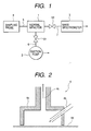
- FIG. 1 is a structural view of an example of an analyzing apparatus including the mass spectrometer of a fine particle concentrating apparatus.
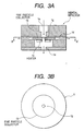
- FIG. 2 is a cross-sectional view of a sampling probe as a fine particle recovery unit.
- FIGS. 3A and 3B are cross-sectional views showing the collection of fine particles using the principle of an inertial impactor as a fine particle collector and a gasifier system.
- a stationary operation type can be considered in which a sampling probe 4 and an inertial impactor 1 are provided as separated structures and the inertial impactor 1 is attached to a mass spectrometric analyzing system 3 or fixed to a stage to be operated.
- a portable type can also be considered in which the inertial impactor 1 is formed integrally with the fine particle recovery unit or disposed in a close proximity to the fine particle collector, as shown in FIG. 9B, such that it connects to an analyzing system via a flow path.
- the embodiment thus illustrates the form having the recovery unit, the collection unit, and the analysis unit
- the recovery unit and the collection unit may also be provided as independent systems.
- the collection unit connecting thereto preferably has the form disclosed in the present embodiment, but it is not limited thereto.
- the recovery unit connecting thereto preferably has the form disclosed in the present embodiment, but it is not limited thereto. It is also possible to provide a system having the recovery unit and the collection unit or a system having the collection unit and the analysis unit. In this case also, the same shall apply.
- Pipes 6 and 7 are also connected to the inertial impactor 1, of which the pipe 6 is connected to the suction pump 2 to exhaust a gas that has passed through the inertial impactor 1 and the pipe 7 is connected to the mass spectrometer 3 to guide a target component to be examined.
- the pipes 5, 6, and 7 are connected to a fine particle entrance path 1a in FIGS. 3A and 3B, to an exhaust path 1d in FIGS. 3A and 3B, and to an extraction flow path 1e in FIGS. 3A and 3B, respectively.
- a valve V1 is disposed in the pipe 6 to adjust an amount of suction by the suction pump 2.
- a valve V2 is connected to the pipe 7 to adjust the gas flowing toward the mass spectrometer 3.
- a description will be given herein below to an example of an application to a dangerous material detecting apparatus for TNT powder, RDX, or the like.
- a mass spectrometric analyzing apparatus equipped with the fine particle concentrating apparatus according to the present invention allows anti-terrorism measures and anti-drug measures for screening out explosives and drugs to be taken for a carry-on luggage check at an airport or the like. It can be considered that these materials are normally present in the state of fine particles and adhered to the surface of luggage such as a bag.
- the materials present in the state of fine particles have an average particle diameter ranging from about 10 ⁇ m to about 30 ⁇ m, though the particle diameters differ depending on the materials.
- the flow rate and the size of the inertial impactor are optimized to allow collection of the fine particles in the size range.
- a consideration will be given to the case where an explosive or the like is adhered in the state of fine particles to the surface of a target obj ect to be measured, such as a bag.
- the fine particles of an explosive or the like adhered to the surface of a bag or the like are removed by spraying an air or like method to be released into an air.
- a method which removes the fine particles by spraying a jet of air or the like can be considered.
- FIG. 2 shows an example of the recovery unit which is the sampling probe using an air jet.
- the recovery unit has a cover 4a, a nozzle 4b for spraying a fluid (which is a compressed air herein) onto a target region with the fine particles adhered thereto which is located inside the cover 4a, and a recovery flow path 4c for recovering the fluid sprayed onto the target region.
- a fluid which is a compressed air herein
- an air is ejected from the nozzle 4b in a direction in which the ejected air approaches the recovery flow path 4c.
- the fine particles are removed from the surface and conveyed through the recovery flow path 4c to the inertial impactor 1.
- a brush structure and a rotating roller structure such as those provided in a vacuum cleaner or the like, are provided so that the fine particles are removed from the surface by bringing them into contact with the surface and operating them.
- a dissociating mechanism such as a roller, a brush, or the like as a replacement for the foregoing gas ejector may also be considered.
- a fluid is ejected preferably in such a case where measurement is performed successively by changing target objects to be measured in consideration of contamination with the fine particles collected from the objects measured previously.
- the gas that has passed through the entrance path extending from the recovery unit to be ejected in divided relation from the ejector flows in a direction different from the direction of ejection to connect to the exhaust path.
- the pipe 5 in FIG. 1 and the fine particle entrance path 1a in FIGS. 3A and 3B correspond thereto.
- the inertial impactor 1 has a property which allows the collection of fine particles having diameters not less than a specified particle diameter and which is determined by the particle diameter, the flow rate, and the nozzle diameter. The fine particles enter the inertial impactor 1 from the flow path 1a.
- the flow path has an end composing the ejector for ejecting the gas containing the recovered fine particles, a fine particle collector 1b disposed in opposing relation to the ejector to cause collisions between the fine particles in the gas, the exhaust flow path 1d in which the gas that has passed through the fine particle collector 1b flows, a heater 1c used as an embodiment of a vaporizer for vaporizing the fine particles collected by the fine particle collector 1b, and the extraction flow path 1e in which the components of the vaporized fine particles flow.
- the flow path is narrower in the outlet than in the inlet of the entrance portion so that the gas under measurement containing the fine particles is accelerated and ejected at a higher flow speed.
- the inertial impactor 1 is constructed such that the gas subsequently flows to the suction pump via the flow path 1d.
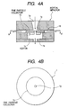
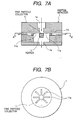
- the flow path 1a is a circular hole becoming larger and smaller in diameter, if the flow path 1a is formed into a nozzle structure such as the nozzle 1a which gradually narrows with approach toward the ejector at the end portion as shown in FIGS. 4A and 4B, efficient suction can be performed by reducing the influence of a pressure loss.
- the reason for providing such a nozzle portion is that, when fine particles are collected, the nozzle 1a of the inertial impactor 1 generally requires a high flow speed in accordance with the following principle.
- a raise in suck-in flow rate can be considered. If it is assumed that the flow path 1a portion of the inertial impactor 1 has the same diameter as the inner diameter of the pipe 5, e.g., the flow rate should be raised to provide a high flow speed.
- the flow speed in the pipe 5 is the same as that in the flow path 1a portion of the inertial impactor 1, i.e., that a pressure loss in the pipe 5 is increased disadvantageously. It can therefore be said that the flow path 1a portion of the inertial impactor 1 having a nozzle configuration suppresses an increase in pressure loss and effective in providing a required high flow speed.
- the flow paths 1a to 1d have a configuration in which they cross orthogonally at the fine particle collector. Consequently, particles having sizes not less than the specified size cannot turn in the direction of the flow path 1d to collide against the fine particle collector 1b so that the fine particles are collected in the fine particle collector 1b.
- the inertial impactor 1 also has the effect of a filter. Uncollected particles having sizes not more than the specified size have been caught in a flow toward the suction pump where they are collected by the suction pump.
- the inertial impactor 1 having a nozzle diameter N of 0.25 (cm) is used when the sampling flow rate ⁇ is 20.0 (1/min), it follows that particles having diameters d in excess of 1. 0 ⁇ m (1.0 x 10 -4 cm) collide against the collector 1b with the 80% collection efficiency and are collected therein.
- the fine particles having diameters not less than the specified diameter are collected in the fine particle collector of the inertial impactor.
- a quantity of fine particles deposited on the fine particle collector can be increased.
- the flow rate involved in mass spectrometric analysis when concentration is not performed ranges from 0.1 (L/min) to 1.0 (L/min). In the present invention, if it is assumed that suction is performed at an exhaust pump flow rate of 10 (L/min) or more, the flow rate ratio therebetween is 30:1 or more.
- the number of fine particles that can be collected and used as target objects to be measured is equal to that in the case where suction is performed at the 30-fold flow rate provided that the suction time is the same. This achieves an improvement in sensitivity directly proportional to the flow rate ratio.
- suction is halted by stopping the suction pump 2 or bringing the valve V1 into a closed state. At this time, the fine particles are deposited in the fine particle collector.
- the region of the flow path located in the vicinity of the fine particle collector 1b is smaller in cross-sectional area than the flow path 1d located downstream thereof. This is because a large pressure loss occurs in the fluid if the cross-sectional area of the flow path 1d is the same as in the vicinity of the fine particle collector, while the gap thickness required by the fine particle collector remains the same, so that it becomes necessary to compensate for the loss resulting from a misoperation of the apparatus due to an insufficient pump output or from the scaling up of the pump.
- the fine particle collector 1b is heated by using the heater 1c attached to the fine particle collector, whereby the deposited fine particles are gasified.
- the heating requires a temperature at which the fine particles as target objects to be measured are evaporated.
- a sheath heater is used as the heater 1c.
- the heating type can perform gasification inside the system and thereby achieves increased sensitivity, saved labor, on-line operation, and higher efficiency.
- the gas thus obtained is supplied from a fine hole 1f provided in the fine particle collector 1b to the mass spectrometric analyzing system through the flow path 1e as the extraction flow path.
- the higher concentration of the gas is achieved by adjusting a gasification time shorter than a collection time.
- the temperature of the fine particle collector 1b is not higher than the evaporation temperature for the fine particles and is controlled to be not lower than the evaporation temperature for the fine particles at the time of vaporization.
- the fine particle collector 1b is forcibly cooled by using a gas stream generated by operating the suction pump 2 or cooled to a specified temperature by adjusting the output of the heater 1c.
- the fine particle collector 1b has a narrowed flow path so that the flow speed of the gas under measurement, which also serves as a cooling gas, is high so that the forcible cooling achieves a high effect. To efficiently perform cooling, it is effective to bring the high temperature portion of the sample collector 1b into contact only with the portion at a high flow speed. It is also effective to reduce the width of the flow path and the size of the sample collector 1b.
- the present embodiment is used in a situation such as a normal space at an airport or the like and the use thereof in a clean environment, such as a clean room, is not assumed. Accordingly, an object to be sucked is a normal atmosphere and it can be considered that extremely fine filth such as dust is contained therein.
- the necessity to collect the fine particles leads to the necessity for a fine-mesh filter so that the frequency with which clogging occurs is increased. As a result, it becomes necessary to replace the filter or check clogging.
- the present embodiment is formed to suppress the occurrence of clogging at the fine particle collector 1b and allow stable collection.
- cleaning can also be performed by raising the flow rate to raise the flow speed in the fine particle collector 1b and thereby removing the adhered dust.
- cleaning can be performed easily by forming the fine particle collector 1b into a simple structure such as a flat plate structure.
- valve V1 At the stage of collecting fine particles, the valve V1 is brought into the open state, while the valve V2 is brought into a closed state. As for the valve V2, it may also be brought into an open state provided that it does not interrupt the operation. This is because, since the suction speed of the mass spectrometer 3 is low compared with the suction speed of the suction pump 2 for the inertial impactor, the influence on a flow formed by the suction pump 2 can be considered to be small. Then, the suction pump 2 is operated to change the direction of the flow path from the flow path 1a at the fine particle collector 1b and then form a flow to the flow path 1d.
- the inertial impactor 1 is formed by properly setting the circumferential size of the fine particle collector so that the fine particles sucked into the fine particle collector 1b are collected.
- the fine particle collector 1b it is necessary for the fine particle collector 1b to have a temperature not higher than the evaporation temperature for the fine particles. If heating by the heater 1c is held constant at a sufficiently high given temperature, e.g., 150 °C, the temperature of the fine particle collector 1b is held constant by adjusting and controlling the output of the heater 1c. This is because a cooling effect is exerted by the suction, as stated previously. If the fine particle collector 1b is to be cooled maximally, it is allowed to cool without performing heating using the heater 1c.
- the evaporation temperature at this time is assumed to be 200 °C, however, a state at a given temperature or higher is preferred to a sufficiently cooled state if consideration is given to the effect of performing heating to a temperature not lower than 200 °C in a short period of time. Accordingly, it is conceivably effective to determine temperatures at which the fine particles are adsorbed but are not evaporated for different materials and perform settings.
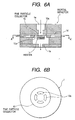
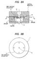
- the fine hole 1g is provided in the center portion of the fine particle collector 1b.
- the heat supplied from the heater 1c flows to the main body of the inertial impactor through the outer peripheral portion thereof, whereby the ultimate temperature and the heating efficiency are lowered.
- fine holes 9a or trenches 10a are formed by enclosing the center portion of the fine particle collector as shown in a fine particle collector 9 of FIGS.
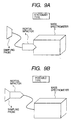
- the thermal path from the center portion is narrowed in the same manner as in the fine particle collector 9 of FIGS. 5A and 5B and in the fine particle collector 10 of FIGS. 6A and 6B and, in addition, the grooves 11a are formed also to the outer circumference. If there are fine particles collected at the outer peripheral portion, therefor, it may be considered that they are efficiently introduced into the mass spectrometric analyzing apparatus. However, it may also be considered that the flow to the exhaust path is interrupted conversely. As shown in FIGS. 8A and 8B, the connection area (heat transfer area) of the support member of the fine particle collector 12 is reduced by providing a spacer 13 in the connecting portion between a fine particle collector 12 and the inertial impactor 1.
- the present embodiment has primarily described the case where the heater 1c is smaller in size than the fine particle collector by way of example, if the heating of the main body side is performed simultaneously with the heating of the fine particle collector by using the heater 1c of the fine particle collector, it can be considered to make provisions by disposing the thermal path from the fine particle collector to the main body portion, by using the heater 1c equal in size to the fine particle collector, or by increasing the output of the heater.
- a reduction in the thickness or size of the fine particle collector 1b of the inertial impactor 1 the use of a material such as aluminum or copper instead of stainless steel, or the like is effective.
- the embodiment described above allows an explosive in the state of fine particles to be collected and introduced into the mass spectrometric analyzer and also allows the sequence of operations of concentrating and gasifying the collected fine particles to be performed. Since this obviates the necessity for operation by a person, the operations can be increased in speed and efficiency. Since concentration is possible, fine particles at a low concentration which are normally difficult to detect can be detected. Furthermore, the simple structure promises improved maintainability and allows improved operation efficiency.
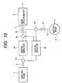
- a second embodiment of the present invention will be describedwith reference to FIGS. 10 to 12.
- the second embodiment can use the structure of the foregoing embodiment and the form in which it is applied.
- the present embodiment is formed to have a plurality of fine particle collectors.
- the arrangement improves the operation efficiency in a sequence of collecting, heat gasifying, and cooling processes bymoving two or more inertial impactors 1 in parallel.
- An example which uses two inertial impactors and operates them in parallel is shown.
- the sampling probe 4 is used commonly, a switch valve V3 is disposed behind the sampling probe 4, and an air is introduced into an arbitrary one of the inertial impactors 1 disposed behind the switch valve V3.
- a switch valve V4 is connected to the pipe 7 connecting to the mass spectrometer 3 and a switch valve V5 is connected to the pipe 6 connecting to the suction pump 2 so that opening and closing control is performed to prevent a backflow or the like in the inertial impactors.
- FIG. 10 illustrates the case where two inertial impactors are used.
- the object of operating the inertial impactors in parallel is to continuously send a sample gas into the mass spectrometer 3.
- the two inertial impactors are termed A and B. It is assumed that collection is performed first by using the inertial impactor 1A.
- the suction pump 2 is operated to switch the switch valves V3 and V5 to the inertial impactor 1A.
- the switch valve V4 is switched to the inertial impactor 1B to prevent the occurrence of suction. While the fine particles of an explosive are collected by using the inertial impactor 1A, the inertial impactor 1B operates the heater 1c such that heat gasification is performed and sends the sample gas to the mass spectrometer 3. Then, the valves V3 and V5 are switched to the position of the inertial impactor 1B. The switch valve V4 is switched to the inertial impactor 1A. While the inertial impactor 1B is performing cooling and collection, the inertial impactor 1Aperforms heat gasification to provide the sample gas.
- FIG. 11 shows a process chart. Since continuous collection can thus be performed, the time during which the supply of the sample gas stops is eliminated and the operation efficiency can be improved.
- the intervals are adj ustedbyproviding a long natural cooling time after heating. Specifically, natural cooling not involving the spraying of an air jet is performed first after heat gasification is completed and then forcible cooling using the air jet is performed. During the natural cooling, the collection and gasification of fine particles are performed by using another impactor.
- FIGS. 12A and 12B show a structure using a rotating mechanism as the mechanism for moving the fine particle collector, in which the fine particle collector and a heat gasifier are provided discretely such that two separate processes are performed. After collecting the fine particles, the collected fine particles are moved to the heat gasifier by rotating a fine collecting plate by 180 degrees. At this time, cooling and collection of the fine particles are performed in the fine particle collector located on the opposite side of the fine particle collecting plate. This allows continuous gasification to be performed in the same manner as in the case where two inertial impactors are used.
- the two collectors are provided in this example, if two or more collectors are provided, it can be considered to achieve higher efficiency by mounting an additional cooling mechanism separately from the collectors and independently providing the collectors, a heater, and a cooler.
- a collector/concentrator and a gasifier as one unit include an application to a portable type involving miniaturization, a cost reduction due to a simpler structure, a reduced amount of fine particles adhered to the wall surface due to a small area in contact with the heated sample gas, a noise reduction, and a reduction in operation time in each process, as stated previously.
Landscapes
- Health & Medical Sciences (AREA)
- Life Sciences & Earth Sciences (AREA)
- Engineering & Computer Science (AREA)
- Biomedical Technology (AREA)
- Molecular Biology (AREA)
- Physics & Mathematics (AREA)
- Chemical & Material Sciences (AREA)
- Analytical Chemistry (AREA)
- Biochemistry (AREA)
- General Health & Medical Sciences (AREA)
- General Physics & Mathematics (AREA)
- Immunology (AREA)
- Pathology (AREA)
- Sampling And Sample Adjustment (AREA)
- Other Investigation Or Analysis Of Materials By Electrical Means (AREA)
Applications Claiming Priority (2)
| Application Number | Priority Date | Filing Date | Title |
|---|---|---|---|
| JP2003323869A JP4085941B2 (ja) | 2003-09-17 | 2003-09-17 | 分析装置 |
| JP2003323869 | 2003-09-17 |
Publications (2)
| Publication Number | Publication Date |
|---|---|
| EP1517129A2 true EP1517129A2 (de) | 2005-03-23 |
| EP1517129A3 EP1517129A3 (de) | 2005-08-10 |
Family
ID=34191291
Family Applications (1)
| Application Number | Title | Priority Date | Filing Date |
|---|---|---|---|
| EP04002716A Withdrawn EP1517129A3 (de) | 2003-09-17 | 2004-02-06 | Analysegerät und Sammelgerät für feine Partikel |
Country Status (3)
| Country | Link |
|---|---|
| US (1) | US7275453B2 (de) |
| EP (1) | EP1517129A3 (de) |
| JP (1) | JP4085941B2 (de) |
Cited By (7)
| Publication number | Priority date | Publication date | Assignee | Title |
|---|---|---|---|---|
| WO2008096270A3 (en) * | 2007-02-06 | 2008-10-30 | Europ De Analisis Diferencial | Method for detecting particles by rapidly preconcentrating said particles by inertial separation |
| CN102154096A (zh) * | 2009-12-25 | 2011-08-17 | 株式会社日立工业设备技术 | 被检测物捕集用具及其使用方法 |
| EP2778650A3 (de) * | 2013-03-15 | 2016-04-20 | Morpho Detection, Inc. | Tragbares Spurenpartikelentnahmesystem und Betriebsverfahren dafür |
| US11112363B2 (en) | 2019-08-05 | 2021-09-07 | Samsung Electronics Co., Ltd. | Apparatus and method for measuring particulate matter |
| US11235329B2 (en) | 2017-08-10 | 2022-02-01 | Rapiscan Systems, Inc. | Systems and methods for substance detection using thermally stable collection devices |
| US11609214B2 (en) | 2019-07-31 | 2023-03-21 | Rapiscan Systems, Inc. | Systems and methods for improving detection accuracy in electronic trace detectors |
| US12411122B2 (en) | 2020-05-12 | 2025-09-09 | Rapiscan Systems, Inc. | Sensitivity traps for electronic trace detection having explosives or narcotics embedded in a plasticized polymer matrix |
Families Citing this family (32)
| Publication number | Priority date | Publication date | Assignee | Title |
|---|---|---|---|---|
| BRPI0609970A2 (pt) * | 2005-04-05 | 2011-10-11 | Ams Res Corp | implante pélvico, instrumento cirúrgico, e, combinação |
| JP4952227B2 (ja) | 2006-01-06 | 2012-06-13 | 富士通株式会社 | 微粒子サイズ選別装置 |
| US7511809B2 (en) * | 2006-07-07 | 2009-03-31 | Itt Manufacturing Enterprises, Inc. | Air sampler module for enhancing the detection capabilities of a chemical detection device or system |
| US7800056B2 (en) * | 2006-10-26 | 2010-09-21 | Smiths Detection Montreal Inc. | Document sampler and method of sampling a document |
| US8104362B2 (en) * | 2008-01-08 | 2012-01-31 | Texas A&M University System | In-line virtual impactor |
| US9791353B2 (en) * | 2008-08-29 | 2017-10-17 | Research International, Inc. | Concentrator |
| CN101900705B (zh) * | 2009-05-25 | 2012-09-05 | 同方威视技术股份有限公司 | 痕量检测仪和用于痕量检测仪的分析方法 |
| JP5658244B2 (ja) * | 2009-07-02 | 2015-01-21 | ザ ガヴァナーズ オブ ザ ユニヴァーシティ オブ アルバータ | 粒子分級器 |
| US20110203931A1 (en) * | 2009-07-13 | 2011-08-25 | Enertechnix, Inc | Particle Interrogation Devices and Methods |
| US8561486B2 (en) * | 2009-07-13 | 2013-10-22 | Enertechnix, Inc | Particle interrogation devices and methods |
| US8307723B2 (en) * | 2009-07-13 | 2012-11-13 | Enertechnix, Inc. | Particle interrogation devices and methods |
| US20110027905A1 (en) * | 2009-08-03 | 2011-02-03 | Henderson Douglas B | Systems and Methods for Collection and Analysis of Analytes |
| US8474335B2 (en) * | 2010-01-12 | 2013-07-02 | Veltek Associates, Inc. | Microbial air sampler |
| US9040905B2 (en) | 2010-11-11 | 2015-05-26 | Hitachi, Ltd. | Analysis device and analysis method |
| JP5077472B2 (ja) * | 2011-10-27 | 2012-11-21 | 株式会社日立プラントテクノロジー | 被検出物捕集具の使用方法 |
| JP5914164B2 (ja) * | 2012-05-23 | 2016-05-11 | 株式会社日立製作所 | 微粒子検出装置及びセキュリティゲート |
| US11787596B2 (en) | 2012-07-12 | 2023-10-17 | Veltek Associates, Inc. | Ergonomic microbial air sampler |
| US10571369B2 (en) | 2012-07-12 | 2020-02-25 | Veltek Associates, Inc. | Ergonomic microbial air sampler |
| JP5310916B2 (ja) * | 2012-08-30 | 2013-10-09 | 株式会社日立プラントテクノロジー | 被検出物捕集具及びこれを備える微生物計数装置 |
| JP5416816B2 (ja) * | 2012-08-30 | 2014-02-12 | 株式会社日立製作所 | 被検出物捕集具の使用方法 |
| CN104662404B (zh) * | 2012-09-21 | 2018-03-09 | 史密斯探测-沃特福特有限公司 | 样品采集热解吸器 |
| JP6002061B2 (ja) * | 2013-02-27 | 2016-10-05 | 株式会社日立製作所 | 微粒子分析装置 |
| JP6227934B2 (ja) * | 2013-08-23 | 2017-11-08 | 株式会社Nttドコモ | ガスの測定装置及びガスの測定方法 |
| JP6581786B2 (ja) * | 2015-03-18 | 2019-09-25 | 株式会社日立ハイテクソリューションズ | 薬物探知装置 |
| FI20165702A (fi) * | 2016-09-19 | 2018-03-20 | Karsa Oy | Laite ja menetelmä pienissä ja keskisuurissa matkatavaroissa olevien laittomien aineiden jäämien seulomiseen |
| JP6876795B2 (ja) * | 2016-11-09 | 2021-05-26 | ザ・ボード・オブ・トラスティーズ・オブ・ザ・ユニバーシティ・オブ・イリノイThe Board Of Trustees Of The University Of Illinois | 粒状物質モニタのための微細加工分別装置 |
| US11906404B2 (en) * | 2017-03-24 | 2024-02-20 | Signature Science, Llc | Aerosol and vapor enhanced sample module |
| CN107436278A (zh) * | 2017-08-28 | 2017-12-05 | 太原海纳辰科仪器仪表有限公司 | 多通道分流结构采样器 |
| GB2583115B (en) * | 2019-04-17 | 2022-09-14 | Ancon Tech Limited | A real-time vapour extracting device |
| JP7445760B2 (ja) * | 2019-11-27 | 2024-03-07 | シムライズ アーゲー | 放出システムからの活性物質の放出に関する分析的及び官能的判定を行うための装置及び方法 |
| CN116367771A (zh) * | 2020-10-14 | 2023-06-30 | Imec 非营利协会 | 用于颗粒采集的采集设备、样本采集器和分析仪器 |
| JP2023013862A (ja) * | 2021-07-16 | 2023-01-26 | 国立研究開発法人宇宙航空研究開発機構 | 電離体の捕集装置及び捕集方法 |
Citations (7)
| Publication number | Priority date | Publication date | Assignee | Title |
|---|---|---|---|---|
| EP0447158A2 (de) | 1990-03-13 | 1991-09-18 | Her Majesty The Queen In Right Of Canada As Represented By The Minister Of Revenue | Detektor für versteckte Sprengstoffe und narkotische Substanzen |
| US5425263A (en) | 1993-06-01 | 1995-06-20 | Barringer Research Limited | Method for inspecting an article for concealed substances |
| US5465607A (en) | 1989-06-09 | 1995-11-14 | Research Corporation Technologies, Inc. | Explosive detection screening system |
| WO1998043063A1 (en) | 1997-03-21 | 1998-10-01 | Aerosol Dynamics Inc. | Integrated collection and vaporization particle chemistry monitoring |
| EP0896213A2 (de) | 1997-08-07 | 1999-02-10 | Scintrex Limited | Vorrichtung zum Sammeln von explosiven und narkotischen Proben |
| US6408701B1 (en) | 1999-05-12 | 2002-06-25 | Nec Corporation | Apparatus for measuring contamination of the surface of a machine surface |
| GB2376873A (en) | 2001-05-31 | 2002-12-31 | Ian Robert Fothergill | Analysis or disposal of surface adherents |
Family Cites Families (6)
| Publication number | Priority date | Publication date | Assignee | Title |
|---|---|---|---|---|
| US3908969A (en) * | 1971-12-20 | 1975-09-30 | Pennsylvania Engineering Corp | Method and apparatus for air pollution control combined with safe recovery and control of gases from a bottom-blown steel converter vessel |
| US3998626A (en) * | 1973-03-12 | 1976-12-21 | Pennsylvania Engineering Corporation | Method for air pollution control combined with safe recovery and control of gases from a bottom-blown steel converter vessel |
| US5964985A (en) * | 1994-02-02 | 1999-10-12 | Wootten; William A. | Method and apparatus for converting coal to liquid hydrocarbons |
| US5854431A (en) | 1997-12-10 | 1998-12-29 | Sandia Corporation | Particle preconcentrator |
| JP3609989B2 (ja) | 2000-06-21 | 2005-01-12 | 大和製罐株式会社 | 気中微粒子検出装置 |
| US6334365B1 (en) | 2000-12-11 | 2002-01-01 | Sandia Corporation | Target detection portal |
-
2003
- 2003-09-17 JP JP2003323869A patent/JP4085941B2/ja not_active Expired - Fee Related
-
2004
- 2004-02-06 EP EP04002716A patent/EP1517129A3/de not_active Withdrawn
- 2004-02-06 US US10/773,743 patent/US7275453B2/en not_active Expired - Fee Related
Patent Citations (7)
| Publication number | Priority date | Publication date | Assignee | Title |
|---|---|---|---|---|
| US5465607A (en) | 1989-06-09 | 1995-11-14 | Research Corporation Technologies, Inc. | Explosive detection screening system |
| EP0447158A2 (de) | 1990-03-13 | 1991-09-18 | Her Majesty The Queen In Right Of Canada As Represented By The Minister Of Revenue | Detektor für versteckte Sprengstoffe und narkotische Substanzen |
| US5425263A (en) | 1993-06-01 | 1995-06-20 | Barringer Research Limited | Method for inspecting an article for concealed substances |
| WO1998043063A1 (en) | 1997-03-21 | 1998-10-01 | Aerosol Dynamics Inc. | Integrated collection and vaporization particle chemistry monitoring |
| EP0896213A2 (de) | 1997-08-07 | 1999-02-10 | Scintrex Limited | Vorrichtung zum Sammeln von explosiven und narkotischen Proben |
| US6408701B1 (en) | 1999-05-12 | 2002-06-25 | Nec Corporation | Apparatus for measuring contamination of the surface of a machine surface |
| GB2376873A (en) | 2001-05-31 | 2002-12-31 | Ian Robert Fothergill | Analysis or disposal of surface adherents |
Cited By (11)
| Publication number | Priority date | Publication date | Assignee | Title |
|---|---|---|---|---|
| US9354153B2 (en) | 2005-08-11 | 2016-05-31 | Morpho Detection, Llc | Hand-held trace particle sampling system and method of operating the same |
| WO2008096270A3 (en) * | 2007-02-06 | 2008-10-30 | Europ De Analisis Diferencial | Method for detecting particles by rapidly preconcentrating said particles by inertial separation |
| CN102154096A (zh) * | 2009-12-25 | 2011-08-17 | 株式会社日立工业设备技术 | 被检测物捕集用具及其使用方法 |
| EP2339321A3 (de) * | 2009-12-25 | 2012-03-14 | Hitachi Plant Technologies, Ltd. | Vorrichtung zur Objektaufnahme und Verfahren zu deren Verwendung |
| CN102154096B (zh) * | 2009-12-25 | 2014-04-30 | 株式会社日立制作所 | 被检测物捕集用具及其使用方法 |
| US9476808B2 (en) | 2009-12-25 | 2016-10-25 | Hitachi Plant Services Co., Ltd. | Device for capturing object and method for using the same |
| EP2778650A3 (de) * | 2013-03-15 | 2016-04-20 | Morpho Detection, Inc. | Tragbares Spurenpartikelentnahmesystem und Betriebsverfahren dafür |
| US11235329B2 (en) | 2017-08-10 | 2022-02-01 | Rapiscan Systems, Inc. | Systems and methods for substance detection using thermally stable collection devices |
| US11609214B2 (en) | 2019-07-31 | 2023-03-21 | Rapiscan Systems, Inc. | Systems and methods for improving detection accuracy in electronic trace detectors |
| US11112363B2 (en) | 2019-08-05 | 2021-09-07 | Samsung Electronics Co., Ltd. | Apparatus and method for measuring particulate matter |
| US12411122B2 (en) | 2020-05-12 | 2025-09-09 | Rapiscan Systems, Inc. | Sensitivity traps for electronic trace detection having explosives or narcotics embedded in a plasticized polymer matrix |
Also Published As
| Publication number | Publication date |
|---|---|
| US20050058575A1 (en) | 2005-03-17 |
| JP4085941B2 (ja) | 2008-05-14 |
| EP1517129A3 (de) | 2005-08-10 |
| US7275453B2 (en) | 2007-10-02 |
| JP2005091118A (ja) | 2005-04-07 |
Similar Documents
| Publication | Publication Date | Title |
|---|---|---|
| US7275453B2 (en) | Analyzing apparatus and fine particle collecting apparatus | |
| JP7504866B2 (ja) | 生産機器および表面上のナノ粒子の検出 | |
| US6217636B1 (en) | Transpirated wall aerosol collection system and method | |
| EP1792161B1 (de) | Vorkonzentrierer zur partikelprobennahme | |
| US9354153B2 (en) | Hand-held trace particle sampling system and method of operating the same | |
| US7002145B2 (en) | Detection method and detection device of special drugs | |
| JP2002525567A (ja) | パルス空気サンプラー | |
| JP4568327B2 (ja) | 付着物検査装置及び付着物検査方法 | |
| US5604319A (en) | Sampling device for gas analyzers | |
| JP2001511257A (ja) | 総合粒子収集気化化学モニタリング | |
| JPWO2020051131A5 (de) | ||
| WO2003089907A1 (en) | Method and apparatus for enhanced particle collection efficiency | |
| Sleeman et al. | Rapid screening of banknotes for the presence of controlled substances by thermal desorption atmospheric pressure chemical ionisation tandem mass spectrometry | |
| EP2267442B1 (de) | Pyrolysator mit doppeltem Auslass für ein Detektionssystem für biologische Agenzien | |
| Luedke et al. | Comparative studies on metal determination in airborne particulates by LA-ICP-MS and furnace atomization non-thermal excitation spectrometry | |
| Furuuchi et al. | High Speed Sampling of Ultra-Fine Ambient Particles using Supersonic Flow | |
| HK1037030A (en) | A valveless gas chromatographic system with pulsed injection and temperature programmed elution |
Legal Events
| Date | Code | Title | Description |
|---|---|---|---|
| PUAI | Public reference made under article 153(3) epc to a published international application that has entered the european phase |
Free format text: ORIGINAL CODE: 0009012 |
|
| AK | Designated contracting states |
Kind code of ref document: A2 Designated state(s): AT BE BG CH CY CZ DE DK EE ES FI FR GB GR HU IE IT LI LU MC NL PT RO SE SI SK TR |
|
| AX | Request for extension of the european patent |
Extension state: AL LT LV MK |
|
| PUAL | Search report despatched |
Free format text: ORIGINAL CODE: 0009013 |
|
| AK | Designated contracting states |
Kind code of ref document: A3 Designated state(s): AT BE BG CH CY CZ DE DK EE ES FI FR GB GR HU IE IT LI LU MC NL PT RO SE SI SK TR |
|
| AX | Request for extension of the european patent |
Extension state: AL LT LV MK |
|
| 17P | Request for examination filed |
Effective date: 20051201 |
|
| AKX | Designation fees paid |
Designated state(s): DE GB |
|
| 17Q | First examination report despatched |
Effective date: 20121102 |
|
| RIC1 | Information provided on ipc code assigned before grant |
Ipc: G01N 1/24 20060101AFI20130930BHEP |
|
| GRAP | Despatch of communication of intention to grant a patent |
Free format text: ORIGINAL CODE: EPIDOSNIGR1 |
|
| INTG | Intention to grant announced |
Effective date: 20140224 |
|
| RIN1 | Information on inventor provided before grant (corrected) |
Inventor name: ISHIKAWA, MASANORI Inventor name: SASAKI, NAOYA Inventor name: MORISHIMA, SHIGENORI Inventor name: NAKA, HIROSHI Inventor name: NAGUMO, KATSUMI |
|
| GRAS | Grant fee paid |
Free format text: ORIGINAL CODE: EPIDOSNIGR3 |
|
| STAA | Information on the status of an ep patent application or granted ep patent |
Free format text: STATUS: THE APPLICATION IS DEEMED TO BE WITHDRAWN |
|
| 18D | Application deemed to be withdrawn |
Effective date: 20140708 |