EP1517108A2 - Echangeur de chaleur - Google Patents
Echangeur de chaleur Download PDFInfo
- Publication number
- EP1517108A2 EP1517108A2 EP04460027A EP04460027A EP1517108A2 EP 1517108 A2 EP1517108 A2 EP 1517108A2 EP 04460027 A EP04460027 A EP 04460027A EP 04460027 A EP04460027 A EP 04460027A EP 1517108 A2 EP1517108 A2 EP 1517108A2
- Authority
- EP
- European Patent Office
- Prior art keywords
- heat exchanger
- header tank
- end cap
- header
- side walls
- Prior art date
- Legal status (The legal status is an assumption and is not a legal conclusion. Google has not performed a legal analysis and makes no representation as to the accuracy of the status listed.)
- Granted
Links
Images

Classifications
-
- F—MECHANICAL ENGINEERING; LIGHTING; HEATING; WEAPONS; BLASTING
- F28—HEAT EXCHANGE IN GENERAL
- F28D—HEAT-EXCHANGE APPARATUS, NOT PROVIDED FOR IN ANOTHER SUBCLASS, IN WHICH THE HEAT-EXCHANGE MEDIA DO NOT COME INTO DIRECT CONTACT
- F28D1/00—Heat-exchange apparatus having stationary conduit assemblies for one heat-exchange medium only, the media being in contact with different sides of the conduit wall, in which the other heat-exchange medium is a large body of fluid, e.g. domestic or motor car radiators
- F28D1/02—Heat-exchange apparatus having stationary conduit assemblies for one heat-exchange medium only, the media being in contact with different sides of the conduit wall, in which the other heat-exchange medium is a large body of fluid, e.g. domestic or motor car radiators with heat-exchange conduits immersed in the body of fluid
- F28D1/04—Heat-exchange apparatus having stationary conduit assemblies for one heat-exchange medium only, the media being in contact with different sides of the conduit wall, in which the other heat-exchange medium is a large body of fluid, e.g. domestic or motor car radiators with heat-exchange conduits immersed in the body of fluid with tubular conduits
- F28D1/0408—Multi-circuit heat exchangers, e.g. integrating different heat exchange sections in the same unit or heat exchangers for more than two fluids
- F28D1/0426—Multi-circuit heat exchangers, e.g. integrating different heat exchange sections in the same unit or heat exchangers for more than two fluids with units having particular arrangement relative to the large body of fluid, e.g. with interleaved units or with adjacent heat exchange units in common air flow or with units extending at an angle to each other or with units arranged around a central element
- F28D1/0435—Combination of units extending one behind the other
-
- F—MECHANICAL ENGINEERING; LIGHTING; HEATING; WEAPONS; BLASTING
- F28—HEAT EXCHANGE IN GENERAL
- F28F—DETAILS OF HEAT-EXCHANGE AND HEAT-TRANSFER APPARATUS, OF GENERAL APPLICATION
- F28F9/00—Casings; Header boxes; Auxiliary supports for elements; Auxiliary members within casings
- F28F9/02—Header boxes; End plates
- F28F2009/0285—Other particular headers or end plates
- F28F2009/0287—Other particular headers or end plates having passages for different heat exchange media
-
- F—MECHANICAL ENGINEERING; LIGHTING; HEATING; WEAPONS; BLASTING
- F28—HEAT EXCHANGE IN GENERAL
- F28F—DETAILS OF HEAT-EXCHANGE AND HEAT-TRANSFER APPARATUS, OF GENERAL APPLICATION
- F28F2220/00—Closure means, e.g. end caps on header boxes or plugs on conduits
Definitions
- the invention relates to a heat exchanger comprising a cooling core consisting of a plurality of parallel tubes and cooling fins, two header tanks fluidly connected with opposite ends of each tube and end caps brazed to and tightly closing upper and lower ends of each header tank.
- the invention relates also to an integrated module comprising two heat exchangers of this type and coupled with common end caps, in particular a vehicle CRFM (Condenser, Radiator, cooling Fan Module).
- CRFM Condenser, Radiator, cooling Fan Module
- brackets used to secure the heat exchanger to a vehicle chassis or as supporting points or bases for fixing other elements, in particular a fan and a fan shroud.
- the brackets should have the suitable rigidity, reliability of the attachment and resistance to mechanical vibrations generated during operation of the heat exchanger. It is also a desirable feature if the heat exchanger or an integrated CRFM module enables a one-shot brazing operation, which improves the process of manufacturing the heat exchanger and decreases its costs.
- U.S. Pat 5,441,100 discloses a heat exchanger having headers closed with end caps having a pin protruded upward or downward and integral with a cap, which is used to mount the heat exchanger on a structural base, such as vehicle chassis.
- the object of the present invention is to provide a heat exchanger or a CRFM module of the type mentioned above, having end caps brazed to and tightly closing upper and lower ends of each header tank, that have a simple one-part and economic construction, ensure a leakproofness of connection and enables a one-shot brazing operation of the heat exchanger or the integrated module.
- Another object of the present invention is to provide the heat exchanger having end caps that may be used to mount the heat exchanger e.g. to a vehicle chassis and/or as an assembly feature or bracket for fixing additional elements, such as puller and pusher shroud, wires, cables, etc.
- each end cap has a flat surface closing and recessed inside the header tank profile and provided with a bead on the periphery thereof, and at least two protrusions adjoining to the side walls of the header tank and provided with C-shaped latches, the ends of which engage on the corresponding projections provided on external side walls of header tank.
- the end caps serve as a separator, providing leakproofness of connection and as an assembly feature (bracket) for additional elements.
- the end cap is assembled to the heat exchanger through a snap connection, which assures its position and protect from self movement during the brazing operation.
- the flat recessed surfaces of the end caps block the header tank and the end cap from displacements in relation to each other. Such displacements might occur due to thermal expansion during the furnace brazing operation. Furthermore the recessed surfaces ensure increased surface of joint between the end cap and the header tank.
- the end cap may be used in various types of heat exchangers, providing the shape and dimensions of the header tanks profiles are the same and their walls are provided with projections. The projections can easily be made by chiselling, the Tog lock method or any other suitable way, known to a person skilled in the art.
- the end cap can also serve as a connector coupling two heat exchangers of the integrated CRFM module.
- the circumferential bead extends into a circumferential wall.
- the C-shaped portion of the end cap has at least one, preferably circular aperture.
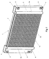
- Fig. 1 shows an integrated vehicle CRFM module comprising two heat exchangers: vehicle's cooling system radiator 1, and the condenser of a vehicle air condition system 1 a.
- the main component of each heat exchanger 1 (1 a) is a cooling core 2 (2a) comprising of a plurality of parallel tubes and cooling fins disposed between the tubes, which are fluidly connected with two header tanks 3 (3a).
- a cooling core 2 (2a) comprising of a plurality of parallel tubes and cooling fins disposed between the tubes, which are fluidly connected with two header tanks 3 (3a).
- the heat exchangers 1 and 1 a are coupled with each other by means of four end caps 4 tightly closing upper and lower ends of the headers 3 and 3a of the heat exchangers 1 and 1 a respectively, so as to form an integrated CRFM.
- Each embodiment 4, 4a, 4b and 4c of the end cap shown in Fig. 1 to Fig. 6, has a form of a single-element shape, manufactured by die-stamping of the metal sheet, preferably brazing-material-clad-aluminium sheet.
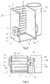
- Fig. 2 and Fig 3 show the end cap 4a in cross-sectional perspective view and in front view respectively, along with portions of the header tanks 3 and 3a of the heat exchangers 1 and 1a.
- the end cap 4a has two similar flat surfaces, of which only one, the surface 5 closing the header tank 3 is shown.
- Surface 5 is perpendicular to the header tank 3 longitudinal axis and depressed inside the header tank 3.
- the flat surface 5 on the periphery thereof is provided with a circumferential bead 7 that improves the leakproofness and strength of connection between the header tank 3 and the end cap 4 after brazing.
- the end cap 4 has two protrusions 8 adjoining the side walls of the header tank 3 and two protrusions 8a (only one shown on the drawing) adjoining the side walls of the second header tank 3a.
- Each protrusion 8 and 8a extends vertically and is provided with C-shaped latches 9 and 9a, respectively, which engage on the corresponding projections 10 and 10a provided on side walls of header tanks 3, 3a.
- each C-shaped latch 9 and 9a has four bend portions indicated successively as 11a, 11b, 11c and 11d.
- the first 11a and the third 11c portion are perpendicular to the side walls of the header tank 3, while the second 11b and the fourth 11d portions are parallel to the wall of the header tank 3.
- the endmost fourth portion 11d adjoins the side walls of the header tank 3 pointing back to the end of the header tank 3 and its edge engages on the top surface of the projection 10.
- the projections 10 are placed on both side walls of the rectangular header tank 3 that are perpendicular to its flat face 12 with apertures 13 for tubes of the cooling core 2. Furthermore the second bend portion 11b is provided with circular apertures 14, enabling mounting a CRFM to a vehicle chassis.
- the construction of protrusions 8a and latches 9a is similar; however the apertures are not present here.
- the header tanks 3 and 3a with projections 10 and 10a.
- the projections may be preferably made by means of chiselling of the header tanks walls or another method of deforming the walls of the header tanks 3 and 3a that permits to form edges on which the C-shaped latches 9 and 9a may engage, e.g. the Tog lock method.
- Fig. 4 shows another embodiment of the end cap 4b for closing only one heat exchanger.
- the construction of the end cap 4b is simpler, since the flat surface 5 of the end cap corresponds to the virtual end surface of only one header tank 3.
- the C-shaped latch 9 of the protrusion 8 has only three bend portions (11a, 11b and 11c) while the endmost bend portion 11c is perpendicular to side wall of the header tank 3 and engages on the projection 10, made by the Tog lock method.
- the C-shaped latch 9 comprises of only two bend portions 11b and 11c.
- the first bend portion 11b is inclined to the side wall of the header tank 3 and the second bend portion 11c is perpendicular to the side wall of the header tank 3.
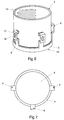
- end cap 4d is shown in Fig. 6 and Fig. 7.
- the end cap is a closing part or separator of a circular header tank 3.
- the end cap 4d has a flat surface 5 surrounded by a circumferential wall 6 and is provided with three protrusions 8 comprising latches 9 having a similar construction to that shown in Fig. 4 and placed equidistantly on the perimeter of the header tank 3.
- the edge of the third bend portion 11c engages with the projection 10 and its surface corresponds to a curvature of the header tank 3.
Landscapes
- Engineering & Computer Science (AREA)
- Physics & Mathematics (AREA)
- Thermal Sciences (AREA)
- Mechanical Engineering (AREA)
- General Engineering & Computer Science (AREA)
- Heat-Exchange Devices With Radiators And Conduit Assemblies (AREA)
Priority Applications (1)
| Application Number | Priority Date | Filing Date | Title |
|---|---|---|---|
| EP04460027.8A EP1517108B1 (fr) | 2003-09-10 | 2004-06-28 | Echangeur de chaleur |
Applications Claiming Priority (3)
| Application Number | Priority Date | Filing Date | Title |
|---|---|---|---|
| GB0321092 | 2003-09-10 | ||
| GBGB0321092.9A GB0321092D0 (en) | 2003-09-10 | 2003-09-10 | Radiator for a motor vehicle |
| EP04460027.8A EP1517108B1 (fr) | 2003-09-10 | 2004-06-28 | Echangeur de chaleur |
Publications (3)
| Publication Number | Publication Date |
|---|---|
| EP1517108A2 true EP1517108A2 (fr) | 2005-03-23 |
| EP1517108A3 EP1517108A3 (fr) | 2009-05-06 |
| EP1517108B1 EP1517108B1 (fr) | 2016-06-22 |
Family
ID=34466368
Family Applications (1)
| Application Number | Title | Priority Date | Filing Date |
|---|---|---|---|
| EP04460027.8A Not-in-force EP1517108B1 (fr) | 2003-09-10 | 2004-06-28 | Echangeur de chaleur |
Country Status (1)
| Country | Link |
|---|---|
| EP (1) | EP1517108B1 (fr) |
Cited By (5)
| Publication number | Priority date | Publication date | Assignee | Title |
|---|---|---|---|---|
| EP1870659A1 (fr) * | 2006-06-21 | 2007-12-26 | Behr France Hambach S.A.R.L. | Dispositif de fermeture, en particulier pour chambre de distribution d'un échangeur de chaleur |
| WO2008025617A1 (fr) * | 2006-08-31 | 2008-03-06 | Valeo Systemes Thermiques | Boitier de distribution d'un fluide caloporteur pour un echangeur de chaleur et echangeur de chaleur comportant un tel boitier |
| FR2905452A1 (fr) * | 2006-08-31 | 2008-03-07 | Valeo Systemes Thermiques | Boitier de distribution d'un fluide pour echangeur de chaleur et echangeur de chaleur comportant un tel boitier. |
| FR2914411A1 (fr) * | 2007-03-30 | 2008-10-03 | Valeo Systemes Thermiques | Boitier de distribution pour echangeur de chaleur et echangeur de chaleur comportant un tel boitier |
| WO2016075320A1 (fr) * | 2014-11-14 | 2016-05-19 | Valeo Systemes Thermiques | Dispositif de fixation pour échangeur de chaleur |
Citations (2)
| Publication number | Priority date | Publication date | Assignee | Title |
|---|---|---|---|---|
| US5441100A (en) * | 1992-06-02 | 1995-08-15 | Showa Aluminum Corporation | Heat exchanger |
| US20010004010A1 (en) * | 1998-02-09 | 2001-06-21 | Immanuel Halm | Heat exchanger having snap-on bracket |
-
2004
- 2004-06-28 EP EP04460027.8A patent/EP1517108B1/fr not_active Not-in-force
Patent Citations (2)
| Publication number | Priority date | Publication date | Assignee | Title |
|---|---|---|---|---|
| US5441100A (en) * | 1992-06-02 | 1995-08-15 | Showa Aluminum Corporation | Heat exchanger |
| US20010004010A1 (en) * | 1998-02-09 | 2001-06-21 | Immanuel Halm | Heat exchanger having snap-on bracket |
Cited By (8)
| Publication number | Priority date | Publication date | Assignee | Title |
|---|---|---|---|---|
| EP1870659A1 (fr) * | 2006-06-21 | 2007-12-26 | Behr France Hambach S.A.R.L. | Dispositif de fermeture, en particulier pour chambre de distribution d'un échangeur de chaleur |
| WO2008025617A1 (fr) * | 2006-08-31 | 2008-03-06 | Valeo Systemes Thermiques | Boitier de distribution d'un fluide caloporteur pour un echangeur de chaleur et echangeur de chaleur comportant un tel boitier |
| FR2905452A1 (fr) * | 2006-08-31 | 2008-03-07 | Valeo Systemes Thermiques | Boitier de distribution d'un fluide pour echangeur de chaleur et echangeur de chaleur comportant un tel boitier. |
| FR2914411A1 (fr) * | 2007-03-30 | 2008-10-03 | Valeo Systemes Thermiques | Boitier de distribution pour echangeur de chaleur et echangeur de chaleur comportant un tel boitier |
| WO2016075320A1 (fr) * | 2014-11-14 | 2016-05-19 | Valeo Systemes Thermiques | Dispositif de fixation pour échangeur de chaleur |
| FR3028605A1 (fr) * | 2014-11-14 | 2016-05-20 | Valeo Systemes Thermiques | Dispositif de fixation pour echangeur de chaleur |
| JP2017534043A (ja) * | 2014-11-14 | 2017-11-16 | ヴァレオ システム テルミク | 熱交換器用取付装置 |
| US10458726B2 (en) | 2014-11-14 | 2019-10-29 | Valeo Systemes Thermiques | Attachment device for heat exchanger |
Also Published As
| Publication number | Publication date |
|---|---|
| EP1517108A3 (fr) | 2009-05-06 |
| EP1517108B1 (fr) | 2016-06-22 |
Similar Documents
| Publication | Publication Date | Title |
|---|---|---|
| US6460610B2 (en) | Welded heat exchanger with grommet construction | |
| US7117927B2 (en) | Snap-on mounting bracket for heat exchangers | |
| US20070131404A1 (en) | Heat exchanger | |
| JP5660024B2 (ja) | 熱交換器の組付け構造 | |
| CN102667393B (zh) | 热交换器的集管器 | |
| US20070074860A1 (en) | Heat exchanger | |
| US20070261835A1 (en) | Collar Rib for Heat Exchanger Headers Tanks | |
| US6607025B2 (en) | Heat-exchange module for a motor vehicle | |
| EP1517108B1 (fr) | Echangeur de chaleur | |
| JP4505955B2 (ja) | 送風機の取付構造 | |
| US20020084064A1 (en) | Integrated heat exchanger support and sealing structure | |
| JP2898800B2 (ja) | 熱交換器 | |
| EP0938990A1 (fr) | Echangeur de chaleur pour véhicules, comprenant un élément pour le positionnement et la fixation saillant par rapport au corps d'échangeur de chaleur | |
| US20070256818A1 (en) | Tank structure of heat exchanger and method for manufacturing the same | |
| JPH0729419Y2 (ja) | 熱交換器 | |
| EP1515105A2 (fr) | Echangeur de chaleur combiné et procédé de fabrication | |
| EP3196583A1 (fr) | Plaque latérale compacte pour condenseur d'automobile | |
| JPH0612383Y2 (ja) | 熱交換器用ヘツダ・タンク | |
| JP2003130580A (ja) | 熱交換器のタンク組付け構造 | |
| JP2003130578A (ja) | 熱交換器 | |
| JP2024013037A (ja) | 熱交換器 | |
| AU2003200154B2 (en) | Welded Heat Exchanger with Grommet Construction | |
| JP2003307398A (ja) | 熱交換器 | |
| JP3680455B2 (ja) | 車両用熱交換器 | |
| JP2009097731A (ja) | 熱交換器のタンク及びその仮組み用治具 |
Legal Events
| Date | Code | Title | Description |
|---|---|---|---|
| PUAI | Public reference made under article 153(3) epc to a published international application that has entered the european phase |
Free format text: ORIGINAL CODE: 0009012 |
|
| AK | Designated contracting states |
Kind code of ref document: A2 Designated state(s): AT BE BG CH CY CZ DE DK EE ES FI FR GB GR HU IE IT LI LU MC NL PL PT RO SE SI SK TR |
|
| AX | Request for extension of the european patent |
Extension state: AL HR LT LV MK |
|
| PUAL | Search report despatched |
Free format text: ORIGINAL CODE: 0009013 |
|
| AK | Designated contracting states |
Kind code of ref document: A3 Designated state(s): AT BE BG CH CY CZ DE DK EE ES FI FR GB GR HU IE IT LI LU MC NL PL PT RO SE SI SK TR |
|
| AX | Request for extension of the european patent |
Extension state: AL HR LT LV MK |
|
| 17P | Request for examination filed |
Effective date: 20091106 |
|
| AKX | Designation fees paid |
Designated state(s): AT BE BG CH CY CZ DE DK EE ES FI FR GB GR HU IE IT LI LU MC NL PL PT RO SE SI SK TR |
|
| GRAP | Despatch of communication of intention to grant a patent |
Free format text: ORIGINAL CODE: EPIDOSNIGR1 |
|
| INTG | Intention to grant announced |
Effective date: 20150610 |
|
| RAP1 | Party data changed (applicant data changed or rights of an application transferred) |
Owner name: MAHLE INTERNATIONAL GMBH |
|
| GRAS | Grant fee paid |
Free format text: ORIGINAL CODE: EPIDOSNIGR3 |
|
| GRAA | (expected) grant |
Free format text: ORIGINAL CODE: 0009210 |
|
| AK | Designated contracting states |
Kind code of ref document: B1 Designated state(s): AT BE BG CH CY CZ DE DK EE ES FI FR GB GR HU IE IT LI LU MC NL PL PT RO SE SI SK TR |
|
| REG | Reference to a national code |
Ref country code: GB Ref legal event code: FG4D |
|
| REG | Reference to a national code |
Ref country code: CH Ref legal event code: EP Ref country code: FR Ref legal event code: PLFP Year of fee payment: 13 |
|
| REG | Reference to a national code |
Ref country code: IE Ref legal event code: FG4D |
|
| REG | Reference to a national code |
Ref country code: AT Ref legal event code: REF Ref document number: 807910 Country of ref document: AT Kind code of ref document: T Effective date: 20160715 |
|
| REG | Reference to a national code |
Ref country code: DE Ref legal event code: R096 Ref document number: 602004049469 Country of ref document: DE |
|
| REG | Reference to a national code |
Ref country code: NL Ref legal event code: MP Effective date: 20160622 |
|
| PG25 | Lapsed in a contracting state [announced via postgrant information from national office to epo] |
Ref country code: FI Free format text: LAPSE BECAUSE OF FAILURE TO SUBMIT A TRANSLATION OF THE DESCRIPTION OR TO PAY THE FEE WITHIN THE PRESCRIBED TIME-LIMIT Effective date: 20160622 |
|
| REG | Reference to a national code |
Ref country code: AT Ref legal event code: MK05 Ref document number: 807910 Country of ref document: AT Kind code of ref document: T Effective date: 20160622 |
|
| PG25 | Lapsed in a contracting state [announced via postgrant information from national office to epo] |
Ref country code: NL Free format text: LAPSE BECAUSE OF FAILURE TO SUBMIT A TRANSLATION OF THE DESCRIPTION OR TO PAY THE FEE WITHIN THE PRESCRIBED TIME-LIMIT Effective date: 20160622 Ref country code: GR Free format text: LAPSE BECAUSE OF FAILURE TO SUBMIT A TRANSLATION OF THE DESCRIPTION OR TO PAY THE FEE WITHIN THE PRESCRIBED TIME-LIMIT Effective date: 20160923 Ref country code: SE Free format text: LAPSE BECAUSE OF FAILURE TO SUBMIT A TRANSLATION OF THE DESCRIPTION OR TO PAY THE FEE WITHIN THE PRESCRIBED TIME-LIMIT Effective date: 20160622 |
|
| PG25 | Lapsed in a contracting state [announced via postgrant information from national office to epo] |
Ref country code: BE Free format text: LAPSE BECAUSE OF NON-PAYMENT OF DUE FEES Effective date: 20160630 |
|
| PG25 | Lapsed in a contracting state [announced via postgrant information from national office to epo] |
Ref country code: SK Free format text: LAPSE BECAUSE OF FAILURE TO SUBMIT A TRANSLATION OF THE DESCRIPTION OR TO PAY THE FEE WITHIN THE PRESCRIBED TIME-LIMIT Effective date: 20160622 Ref country code: RO Free format text: LAPSE BECAUSE OF FAILURE TO SUBMIT A TRANSLATION OF THE DESCRIPTION OR TO PAY THE FEE WITHIN THE PRESCRIBED TIME-LIMIT Effective date: 20160622 Ref country code: EE Free format text: LAPSE BECAUSE OF FAILURE TO SUBMIT A TRANSLATION OF THE DESCRIPTION OR TO PAY THE FEE WITHIN THE PRESCRIBED TIME-LIMIT Effective date: 20160622 Ref country code: CZ Free format text: LAPSE BECAUSE OF FAILURE TO SUBMIT A TRANSLATION OF THE DESCRIPTION OR TO PAY THE FEE WITHIN THE PRESCRIBED TIME-LIMIT Effective date: 20160622 |
|
| REG | Reference to a national code |
Ref country code: CH Ref legal event code: PL |
|
| PG25 | Lapsed in a contracting state [announced via postgrant information from national office to epo] |
Ref country code: BE Free format text: LAPSE BECAUSE OF FAILURE TO SUBMIT A TRANSLATION OF THE DESCRIPTION OR TO PAY THE FEE WITHIN THE PRESCRIBED TIME-LIMIT Effective date: 20160622 Ref country code: AT Free format text: LAPSE BECAUSE OF FAILURE TO SUBMIT A TRANSLATION OF THE DESCRIPTION OR TO PAY THE FEE WITHIN THE PRESCRIBED TIME-LIMIT Effective date: 20160622 Ref country code: PT Free format text: LAPSE BECAUSE OF FAILURE TO SUBMIT A TRANSLATION OF THE DESCRIPTION OR TO PAY THE FEE WITHIN THE PRESCRIBED TIME-LIMIT Effective date: 20161024 Ref country code: PL Free format text: LAPSE BECAUSE OF FAILURE TO SUBMIT A TRANSLATION OF THE DESCRIPTION OR TO PAY THE FEE WITHIN THE PRESCRIBED TIME-LIMIT Effective date: 20160622 Ref country code: ES Free format text: LAPSE BECAUSE OF FAILURE TO SUBMIT A TRANSLATION OF THE DESCRIPTION OR TO PAY THE FEE WITHIN THE PRESCRIBED TIME-LIMIT Effective date: 20160622 |
|
| REG | Reference to a national code |
Ref country code: IE Ref legal event code: MM4A |
|
| REG | Reference to a national code |
Ref country code: DE Ref legal event code: R097 Ref document number: 602004049469 Country of ref document: DE |
|
| PG25 | Lapsed in a contracting state [announced via postgrant information from national office to epo] |
Ref country code: MC Free format text: LAPSE BECAUSE OF FAILURE TO SUBMIT A TRANSLATION OF THE DESCRIPTION OR TO PAY THE FEE WITHIN THE PRESCRIBED TIME-LIMIT Effective date: 20160622 |
|
| PG25 | Lapsed in a contracting state [announced via postgrant information from national office to epo] |
Ref country code: CH Free format text: LAPSE BECAUSE OF NON-PAYMENT OF DUE FEES Effective date: 20160630 Ref country code: LI Free format text: LAPSE BECAUSE OF NON-PAYMENT OF DUE FEES Effective date: 20160630 |
|
| PLBE | No opposition filed within time limit |
Free format text: ORIGINAL CODE: 0009261 |
|
| STAA | Information on the status of an ep patent application or granted ep patent |
Free format text: STATUS: NO OPPOSITION FILED WITHIN TIME LIMIT |
|
| GBPC | Gb: european patent ceased through non-payment of renewal fee |
Effective date: 20160922 |
|
| 26N | No opposition filed |
Effective date: 20170323 |
|
| PG25 | Lapsed in a contracting state [announced via postgrant information from national office to epo] |
Ref country code: IE Free format text: LAPSE BECAUSE OF NON-PAYMENT OF DUE FEES Effective date: 20160628 Ref country code: DK Free format text: LAPSE BECAUSE OF FAILURE TO SUBMIT A TRANSLATION OF THE DESCRIPTION OR TO PAY THE FEE WITHIN THE PRESCRIBED TIME-LIMIT Effective date: 20160622 |
|
| REG | Reference to a national code |
Ref country code: FR Ref legal event code: PLFP Year of fee payment: 14 |
|
| PG25 | Lapsed in a contracting state [announced via postgrant information from national office to epo] |
Ref country code: IT Free format text: LAPSE BECAUSE OF FAILURE TO SUBMIT A TRANSLATION OF THE DESCRIPTION OR TO PAY THE FEE WITHIN THE PRESCRIBED TIME-LIMIT Effective date: 20160622 |
|
| PG25 | Lapsed in a contracting state [announced via postgrant information from national office to epo] |
Ref country code: GB Free format text: LAPSE BECAUSE OF NON-PAYMENT OF DUE FEES Effective date: 20160922 |
|
| PG25 | Lapsed in a contracting state [announced via postgrant information from national office to epo] |
Ref country code: SI Free format text: LAPSE BECAUSE OF FAILURE TO SUBMIT A TRANSLATION OF THE DESCRIPTION OR TO PAY THE FEE WITHIN THE PRESCRIBED TIME-LIMIT Effective date: 20160622 |
|
| PG25 | Lapsed in a contracting state [announced via postgrant information from national office to epo] |
Ref country code: CY Free format text: LAPSE BECAUSE OF FAILURE TO SUBMIT A TRANSLATION OF THE DESCRIPTION OR TO PAY THE FEE WITHIN THE PRESCRIBED TIME-LIMIT Effective date: 20160622 Ref country code: HU Free format text: LAPSE BECAUSE OF FAILURE TO SUBMIT A TRANSLATION OF THE DESCRIPTION OR TO PAY THE FEE WITHIN THE PRESCRIBED TIME-LIMIT; INVALID AB INITIO Effective date: 20040628 |
|
| PG25 | Lapsed in a contracting state [announced via postgrant information from national office to epo] |
Ref country code: LU Free format text: LAPSE BECAUSE OF NON-PAYMENT OF DUE FEES Effective date: 20160628 Ref country code: TR Free format text: LAPSE BECAUSE OF FAILURE TO SUBMIT A TRANSLATION OF THE DESCRIPTION OR TO PAY THE FEE WITHIN THE PRESCRIBED TIME-LIMIT Effective date: 20160622 |
|
| REG | Reference to a national code |
Ref country code: FR Ref legal event code: PLFP Year of fee payment: 15 |
|
| PG25 | Lapsed in a contracting state [announced via postgrant information from national office to epo] |
Ref country code: BG Free format text: LAPSE BECAUSE OF FAILURE TO SUBMIT A TRANSLATION OF THE DESCRIPTION OR TO PAY THE FEE WITHIN THE PRESCRIBED TIME-LIMIT Effective date: 20160622 |
|
| PGFP | Annual fee paid to national office [announced via postgrant information from national office to epo] |
Ref country code: FR Payment date: 20180629 Year of fee payment: 15 |
|
| PGFP | Annual fee paid to national office [announced via postgrant information from national office to epo] |
Ref country code: DE Payment date: 20190830 Year of fee payment: 16 |
|
| PG25 | Lapsed in a contracting state [announced via postgrant information from national office to epo] |
Ref country code: FR Free format text: LAPSE BECAUSE OF NON-PAYMENT OF DUE FEES Effective date: 20190630 |
|
| REG | Reference to a national code |
Ref country code: DE Ref legal event code: R119 Ref document number: 602004049469 Country of ref document: DE |
|
| PG25 | Lapsed in a contracting state [announced via postgrant information from national office to epo] |
Ref country code: DE Free format text: LAPSE BECAUSE OF NON-PAYMENT OF DUE FEES Effective date: 20210101 |