EP1517099A1 - Klimatisierter mobiler Container - Google Patents
Klimatisierter mobiler Container Download PDFInfo
- Publication number
- EP1517099A1 EP1517099A1 EP04021514A EP04021514A EP1517099A1 EP 1517099 A1 EP1517099 A1 EP 1517099A1 EP 04021514 A EP04021514 A EP 04021514A EP 04021514 A EP04021514 A EP 04021514A EP 1517099 A1 EP1517099 A1 EP 1517099A1
- Authority
- EP
- European Patent Office
- Prior art keywords
- brine
- mobile container
- container according
- circuit
- air
- Prior art date
- Legal status (The legal status is an assumption and is not a legal conclusion. Google has not performed a legal analysis and makes no representation as to the accuracy of the status listed.)
- Granted
Links
- 230000001143 conditioned effect Effects 0.000 title description 2
- 238000001816 cooling Methods 0.000 claims abstract description 24
- XLYOFNOQVPJJNP-UHFFFAOYSA-N water Substances O XLYOFNOQVPJJNP-UHFFFAOYSA-N 0.000 claims abstract description 18
- 238000010438 heat treatment Methods 0.000 claims abstract description 12
- 239000012267 brine Substances 0.000 claims description 66
- HPALAKNZSZLMCH-UHFFFAOYSA-M sodium;chloride;hydrate Chemical compound O.[Na+].[Cl-] HPALAKNZSZLMCH-UHFFFAOYSA-M 0.000 claims description 65
- 238000004378 air conditioning Methods 0.000 claims description 37
- 239000003507 refrigerant Substances 0.000 claims description 11
- 238000005192 partition Methods 0.000 claims description 10
- 239000002918 waste heat Substances 0.000 claims description 6
- 230000003750 conditioning effect Effects 0.000 claims description 3
- 238000001704 evaporation Methods 0.000 claims description 3
- 230000008020 evaporation Effects 0.000 claims description 3
- 239000003990 capacitor Substances 0.000 claims description 2
- 239000000498 cooling water Substances 0.000 claims description 2
- 239000002826 coolant Substances 0.000 abstract description 2
- 239000003570 air Substances 0.000 description 60
- 238000010586 diagram Methods 0.000 description 6
- 238000010276 construction Methods 0.000 description 4
- 238000009413 insulation Methods 0.000 description 4
- 238000005057 refrigeration Methods 0.000 description 4
- 239000012080 ambient air Substances 0.000 description 3
- 230000007613 environmental effect Effects 0.000 description 3
- 230000008878 coupling Effects 0.000 description 2
- 238000010168 coupling process Methods 0.000 description 2
- 238000005859 coupling reaction Methods 0.000 description 2
- 239000000428 dust Substances 0.000 description 2
- 238000009434 installation Methods 0.000 description 2
- 239000007788 liquid Substances 0.000 description 2
- 239000004576 sand Substances 0.000 description 2
- 239000002351 wastewater Substances 0.000 description 2
- 230000006978 adaptation Effects 0.000 description 1
- 239000003994 anesthetic gas Substances 0.000 description 1
- 230000009286 beneficial effect Effects 0.000 description 1
- 230000005540 biological transmission Effects 0.000 description 1
- 238000009833 condensation Methods 0.000 description 1
- 230000005494 condensation Effects 0.000 description 1
- 230000003247 decreasing effect Effects 0.000 description 1
- 230000001419 dependent effect Effects 0.000 description 1
- 238000001514 detection method Methods 0.000 description 1
- 238000005485 electric heating Methods 0.000 description 1
- 238000005265 energy consumption Methods 0.000 description 1
- 238000012423 maintenance Methods 0.000 description 1
- 239000000203 mixture Substances 0.000 description 1
- 238000012544 monitoring process Methods 0.000 description 1
- 238000013021 overheating Methods 0.000 description 1
- 230000003134 recirculating effect Effects 0.000 description 1
- 230000001172 regenerating effect Effects 0.000 description 1
- 238000000926 separation method Methods 0.000 description 1
- 238000001356 surgical procedure Methods 0.000 description 1
- 230000001360 synchronised effect Effects 0.000 description 1
- 238000005496 tempering Methods 0.000 description 1
- 238000012360 testing method Methods 0.000 description 1
- 238000012546 transfer Methods 0.000 description 1
- 230000001052 transient effect Effects 0.000 description 1
- 238000009423 ventilation Methods 0.000 description 1
Images




Classifications
-
- A—HUMAN NECESSITIES
- A62—LIFE-SAVING; FIRE-FIGHTING
- A62C—FIRE-FIGHTING
- A62C13/00—Portable extinguishers which are permanently pressurised or pressurised immediately before use
-
- F—MECHANICAL ENGINEERING; LIGHTING; HEATING; WEAPONS; BLASTING
- F24—HEATING; RANGES; VENTILATING
- F24F—AIR-CONDITIONING; AIR-HUMIDIFICATION; VENTILATION; USE OF AIR CURRENTS FOR SCREENING
- F24F3/00—Air-conditioning systems in which conditioned primary air is supplied from one or more central stations to distributing units in the rooms or spaces where it may receive secondary treatment; Apparatus specially designed for such systems
- F24F3/06—Air-conditioning systems in which conditioned primary air is supplied from one or more central stations to distributing units in the rooms or spaces where it may receive secondary treatment; Apparatus specially designed for such systems characterised by the arrangements for the supply of heat-exchange fluid for the subsequent treatment of primary air in the room units
-
- F—MECHANICAL ENGINEERING; LIGHTING; HEATING; WEAPONS; BLASTING
- F24—HEATING; RANGES; VENTILATING
- F24F—AIR-CONDITIONING; AIR-HUMIDIFICATION; VENTILATION; USE OF AIR CURRENTS FOR SCREENING
- F24F11/00—Control or safety arrangements
- F24F11/0001—Control or safety arrangements for ventilation
- F24F2011/0006—Control or safety arrangements for ventilation using low temperature external supply air to assist cooling
-
- F—MECHANICAL ENGINEERING; LIGHTING; HEATING; WEAPONS; BLASTING
- F24—HEATING; RANGES; VENTILATING
- F24F—AIR-CONDITIONING; AIR-HUMIDIFICATION; VENTILATION; USE OF AIR CURRENTS FOR SCREENING
- F24F2221/00—Details or features not otherwise provided for
- F24F2221/44—Protection from terrorism or theft
Definitions
- the invention relates to an air-conditioned mobile container according to the preamble of claim 1
- Container (often referred to as a shelter) of different sizes.
- the application area includes temperatures from at least -32 to + 49 ° C, high humidities, sand and dust.
- the ambient temperatures that exceed the maximum not insignificant.
- the hygiene of the air exchange including ABC protection.
- the Mobility of the overall system aggravates the need for high reliability and partial redundancy. And overall that should help to realize this technical requirements required construction volume remain as small as possible to the Working space of the container for the need of the technical room not too restrictive to have to.
- JP 2003065559 A an air conditioner of two functionally identical submodules for air conditioning of two rooms is described.
- the sub-modules can be operated either independently of each other or together, such that the cooling air flows of the sub-modules can be divided in different proportions to the rooms to be air-conditioned.
- the mobile container according to the invention comprises a work space and a associated with the container engineering space, either a subspace of the container forms or is a separate housing.
- the technical room contains for cooling, Heating and fresh air supply of the working space an air conditioning. Because the used air conditioning for temperature control and fresh air supply, not However, designed for the control of humidity, such air conditioning often referred to as partial air conditioning.
- the air conditioning is cold water air conditioning formed and includes in addition to a coolant circuit with a so coupled brine circuit.
- a brine circuit is with at least one convector, preferably designed as a fan coil coupled within the work space is installed.
- the fresh air supply (both for Normal operation as well as for ABC operation), preferably directly through the partition takes place, requires comparatively small flow cross-sections.
- the cold water air conditioning system comprises in an advantageous embodiment several, preferably two functionally (not necessarily in terms of performance) identical and coupled sub-modules, both independently and as well can be operated together.
- the brine circuits of the submodules are also with one or more convectors, preferably fan convectors, coupled. Fan convectors for the temperature control of the circulating air are within the Workroom installed.
- the two sub-modules can advantageously certain cooling functions within the Be assigned to a whole system: a sub-module may be wholly or used for the air conditioning of the circulating air, while another sub-module used wholly or mainly for the air conditioning of the intake fresh air becomes.
- Each of the brine circuits is, preferably via quick-release couplings, with at least coupled to a fan coil, of which at least one of the Temperature control of the circulating air is located within the working space.
- High-pressure disturbances in the refrigerant circuit are in a known manner by the Installation of a MOP valve (maximum opening pressure) avoided.
- MOP valve maximum opening pressure
- the performance of the Cold water air conditioning on two or more functionally identical and with each other be split coupled submodules.
- This is next to the independent one Operation of each module also a joint operation of two or more Submodules possible to achieve partial redundancy.
- the brine circuits of two sub-modules interconnected so that the brine pumps alternately the other Keep the circuit in operation and also switch both pumps to one circuit can. If one pump fails, both circuits can also be driven by the same pump be circulated.
- both evaporator heat exchanger in series to one Switch brine circuit. This cools the circulating air and thus the working space accelerates, with the associated fan coil for this operating point must be sized.
- the necessary amount of circulating air results from the acceptable temperature difference between air inlet and air outlet on the fan coil.
- the fresh air quantity or number of air changes specified by DIN standards for civil applications and stationary systems must be handled more flexibly for mobile systems. This also in terms of security of supply under limited conditions, such as limited power supply (device priority), technical damage cases, fewer people, stand-by operation. In any case, it makes more sense to keep the room temperature at a tense power supply than the fresh air flow of 20 to 40 m 3 / h person.
- the brine circuit can also be used advantageously as a heat carrier when in cold regions must be heated (heating demand due to transmission losses and fresh air heating).
- the flow through the evaporator heat exchanger is short-circuited.
- One or more electric heating coil are flowed around by the brine. Any possible use of the waste heat of the diesel generator unit needed another heat exchanger for diesel cooling water / brine. It is true in two circles around a liquid of the same composition, in the interest of the modular construction and reliability, however, a separation is advantageous.
- the fresh air supply in the ABC case is made by a high-pressure fan and Filter existing aggregate, which due to a strict type test for the Special application not modified or with other subsystems except the one and the other Shutdown and the air duct can be networked.
- a high-pressure fan and Filter existing aggregate due to a strict type test for the Special application not modified or with other subsystems except the one and the other Shutdown and the air duct can be networked.
- all other air inlets must be closed and the air outlet must be via a pressure relief valve.
- the system control and electrical power supply compares to stationary installations supplied by a stable interconnected grid following features. All electrical consumers are in accordance with their Demand priority locked so that a given maximum value of consumption is not is exceeded. That is, e.g. in the case of a high starting current consumer lower priority can be switched off early, even in transient Operating situations not to exceed the maximum power. Even with a strong The system does not come to a standstill due to reduced external service but automatically adapts to the offer by reducing the load.
- Monitoring and control means are correspondingly aggressive Environmental conditions and increased operational reliability. These include the electrical and thermal control of the start-up of the refrigeration compressor, service life extension and speed grading or regulation of the various fans.
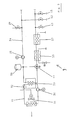
- FIG. 1 shows the overview diagram of the container according to the invention with a technical room 1 and to be conditioned working space 2 in a first embodiment.
- the two submodules of the cold water air conditioning system are installed in the Engineering room 1.
- she include as essential components, the refrigerant circuits 91,101 and the brine circuits 4.5.
- Both sub-modules 9,10 are connected to a respective fan coil 15,17, which are both within the working space 2 in this embodiment.
- the channel 6 becomes passed through the shut off in ABC operation opening 13 into the working space 2 and, combined with the sucked circulating air flow 14, the first fan coil 15 supplied.
- the Fan convector 15 connected in series with the second fan coil 17. in the ABC case, the fresh air supply via the unit 8, which is essential Components includes a high-pressure fan and filters.
- the pressure holding valve 18 stabilizes, especially during ABC operation, the interior pressure above ambient pressure. This airflow can also the air conditioning of a directly by sluice connected adjacent container serve.
- an outlet 19 through the partition wall 3 is possible to the opposite the ambient air much cooler exhaust air in order to increase the Kondensatorkühlmaschine to mix with the ambient air 11.
- FIG. 2 differs from that shown in FIG Execution characterized in that the fresh air in line 6 air conditioning fan coil 15 is arranged in the technical room 1. This shifts necessary Plant construction volume from the working space 2 into the technical room 1. The circulating air 14 must then enter the fan coil 17.
- FIG. 3 shows a more detailed block diagram of a cold water conditioning system as required. as indicated in Fig. 2 by reference numeral 9 or 10.
- the Refrigerant circuit 91 is independent of the cooling capacity in a known manner from the refrigeration compressor 30, the condenser with fan 31, the expansion valve 32 and the evaporator plate heat exchanger 33 together.
- the brine circuit 34 is circulated by the pump 35.
- the heat exchanger 36 can in winter operation Diesel waste heat to be fed, the device 37 is the electrical Heating the brine.
- the equalization tank, with 39 of the filling, with 40 denotes the drain.
- the solenoid valve 41 a short circuit of Brine circuit to be created when starting the compressor at high Initial temperatures to avoid high pressure failure. 42 and 43 denote the connecting pieces of the brine supply and return for any required air conditioning external rooms or to the external supply of brine.
- FIG. 4 is an interconnection of the heat exchangers 33a, b associated brine circuits 34a, b with the circulation pumps 35a, b shown.
- FIG. 5 a-i For the individual operating modes, the flow paths of the brine in FIG. 5 a-i shown schematically. This shows thick line thicknesses of the brine pipes and blackened valve symbols to the proper flow.
Landscapes
- Engineering & Computer Science (AREA)
- Health & Medical Sciences (AREA)
- Public Health (AREA)
- Business, Economics & Management (AREA)
- Emergency Management (AREA)
- Chemical & Material Sciences (AREA)
- Combustion & Propulsion (AREA)
- Mechanical Engineering (AREA)
- General Engineering & Computer Science (AREA)
- Other Air-Conditioning Systems (AREA)
- Air Bags (AREA)
- Central Air Conditioning (AREA)
Abstract
Description
- Kältemittelkreis, umfassend Kälteverdichter, Kondensator mit Gebläse, Expansionsventil, Plattenwärmetauscher Kältemittel/Sole als Verdampfer sowie
- Solekreis, umfassend Solepumpe und Ausgleichsgefäß und
- elektrische Verteilung und Verkabelung
- Der Nennwert der Kühlleistung zur Teilklimatisierung und Frischluftversorgung setzt sich aus der Leistung zweier Anlagen zusammen.
- Die Medienströme (Sole, Luft) sind zwischen beiden Teilmodulen der Klimaanlage umschaltbar.
- Ein teilredundanter Betrieb ist möglich.
- Freie Kühlung und Kondensatorkühlung mit Abluft und Kondenswasser senken den Energiebedarf und erhöhen die Kühlleistung bei Extrembedingungen.
- Der Frischluftbedarf wird durch Sensoren überwacht und in Extremfällen erhöht bzw. verringert.
- Anlagenstillstand bei thermischen Extrembedingungen wird durch die Möglichkeit des Teillastbetriebes vermieden.
- Vorklimatisierung des Raumes (Stand-by, Transport-Betrieb) mit geringerem Energieaufwand.
- Die Umschaltung auf eine ABC-gefilterte Frischluftversorgung ist möglich.
- Die Umschaltung auf Heizbetrieb kann automatisch erfolgen. Die Heizleistung kann dem Heizbedarf angepasst werden (z.B. Zuschaltung Abwärmenutzung Dieselmotor).
- Fig. 1
- das Übersichtsblockschaltbild des erfindungsgemäßen Containers mit dem Technikraum, in dem sich die beiden Teilmodule der Kaltwasser-Klimaanlage befinden, sowie dem Arbeitsraum;
- Fig. 2
- eine Variante der Anordnung nach Fig. 1 mit der Frischluftkühlung im Technikraum;
- Fig. 3
- ein detaillierteres Blockschaltbild eines einzelnen Teilmoduls der Kaltwasser-Klimaanlage mit Heizung;
- Fig. 4
- das Blockschaltbild einer Verschaltung der Solekreise zweier Teilmodule zur Realisierung verschiedener Betriebsweisen;
- Fig. 5a -i
- Blockschaltbilder zur Veranschaulichung der Strömungswege und Ventilstellungen bei verschiedenen Betriebsweisen der Vorrichtung nach Fig. 4.
- Solekreis 34a wird mit Pumpe 35a betrieben und/oder
- Solekreis 34b wird mit Pumpe 35b betrieben.
- Solekreis 34a wird mit Pumpe 35b betrieben (Fig. 5b) oder alternativ:
- Solekreis 34b wird mit Pumpe 35a betrieben (Fig. 5c).
- Solekreis 34a, b wird mit Pumpe 35a betrieben (Fig. 5d) oder alternativ:
- Solekreis 34a, b wird mit Pumpe 35b betrieben (Fig. 5e).
- Solekreis 34a wird mit Pumpe 35a und b betrieben (Fig. 5f) oder alternativ:
- Solekreis 34b wird mit Pumpe 35a und b betrieben (Fig. 5g)
- Pumpe 35a treibt den Solekreis 34a (Fig. 5h) über die beiden Wärmetauscher 33a,b um oder alternativ:
- Pumpe 35b treibt den Solekreis 34b über die beiden Wärmetauscher 33a,b um (Fig. 5i).
Claims (13)
- Mobiler Container mit einem Arbeitsraum (2) sowie einem dem Container zugeordneten Technikraum (1), angeordnet in einem Teilraum des Containers oder in einem separaten Gehäuse, wobei der Technikraum für Kühlung, Heizung und Frischluftversorgung des Arbeitsraums (2) eine Klimaanlage (9,10) enthält, dadurch gekennzeichnet, dass die Klimaanlage eine Kaltwasser-Klimaanlage (9,10) mit Kältemittelkreis (91,101) und damit gekoppeltem Solekreis (4,5) ist, wobei der Solekreise (4,5) mit einem Konvektor (15,17) gekoppelt ist, welcher innerhalb des Arbeitsraums (2) installiert ist.
- Mobiler Container nach Anspruch 1, dadurch gekennzeichnet, dass die Kaltwasser-Klimaanlage aus mindestens zwei funktional identischen und miteinander gekoppelten Teilmodulen (9,10) besteht, die sowohl unabhängig voneinander als auch gemeinsam betrieben werden können, wobei zumindest einer der Konvektoren innerhalb des Arbeitsraums (2) installiert ist.
- Mobiler Container nach einem Anspruch 2, dadurch gekennzeichnet, dass die Teilmodule (9,10) derart miteinander gekoppelt sind, dass die Solekreisläufe (4,5) der Teilmodule (9,10) zusammengeschaltet werden können.
- Mobiler Container nach einem der Ansprüche 2 oder 3, dadurch gekennzeichnet, dass die Teilmodule (9,10) derart miteinander gekoppelt sind, dass die Funktion einer Funktionseinheit des einen Teilmoduls durch die funktionsgleiche Einheit eines anderen Teilmoduls ersetzt oder verstärkt werden kann.
- Mobiler Container nach einem der vorangehenden Ansprüche 2 bis 4, dadurch gekennzeichnet, dass in jedem Solekreis (34a,34b) eines Teilmoduls (9,10) eine Umwälzpumpe (35a,35b) sowie ein Verdampfer-Wärmetauscher (33a,33b) integriert ist, wobei die Solekreise (34a,34b) über Verbindungsleitungen und Ventile (50a,50b,50c,51 a,51 b) derart miteinander verschaltet sind, dass durch Steuerung der Ventile zwischen mindestens zwei der folgenden Betriebsarten umgeschaltet werden kann:Unabhängiger Betrieb jedes einzelnen Solekreises (34a,34b) durch die jeweilige in den Solekreis integrierte Umwälzpumpe (35a,35b),Unabhängiger Betrieb jedes einzelnen Solekreises (34a) durch eine in einem anderen Solekreis (34b) integrierte Umwälzpumpe (35b),Betrieb eines Solekreises (34a) durch Umwälzpumpen (35a,35b) mehrerer Solekreise gemeinsam,Betrieb zweier oder mehrerer Solekreise (34a,34b) durch nur eine der Pumpen (35a),Betrieb zweier Verdampfer-Wärmetauscher (33a,33b) in einem Solekreis (34a,34b).
- Mobiler Container nach einem der vorangehenden Ansprüche, dadurch gekennzeichnet, dass Einrichtungen (36,37) zur Beheizung eines Solekreises (34) vorhanden sind.
- Mobiler Container nach Anspruch 6, dadurch gekennzeichnet, dass ein Anschluss (36) an den Kühlwasserkreis eines externen Dieselgenerator-Aggregats besteht, um für den Heizbetrieb die Motorabwärme in einen oder mehrere Solekreise (34) einzuspeisen.
- Mobiler Container nach einem der vorangehenden Ansprüche, dadurch gekennzeichnet, dass Einrichtungen (42,43) zum Anschluss externer Verbraucher an einem oder mehrere Solekreise (34) vorhanden sind.
- Mobiler Container nach einem der vorangehenden Ansprüche, dadurch gekennzeichnet, dass Einrichtungen zur Einspeisung von gekühlter oder erwärmter Sole von einer externen Klimaanlage in einen oder mehrere Solekreise vorhanden sind, um bei Totalausfall der containereigenen Klimatisierung den Betrieb aufrechtzuerhalten.
- Mobiler Container nach einem der vorangehenden Ansprüche, dadurch gekennzeichnet, dass im Falle eines hohen Leistungsanteils der Frischluftklimatisierung die Abluft des Arbeitsraums durch die Trennwand (3) zwischen Technikraum (1) und Arbeitsraum (2) hindurch der Kühlluft für die Kühlung der Kondensatoren (31) eines Kältemittelkreises (91,101) beigemischt werden kann.
- Mobiler Container nach einem der vorangehenden Ansprüche, dadurch gekennzeichnet, dass im Falle hoher benötigter Kühlleistung das in den Gebläsekonvektoren (15,17) anfallende Kondensat oder Wasser aus einem separaten Wasservorrat (52) zur Verdampfung über dem Kondensator eines Kältemittelkreises (91,101) verdampft werden kann.
- Mobiler Container nach einem der vorangehenden Ansprüche, dadurch gekennzeichnet, dass im Schadensfall einzelner Komponenten die Betriebsweise der Klimaanlage auf einen Notbetrieb umgeschaltet wird, der unter den gegebenen Bedingungen der maximalen Klimaversorgung am nächsten kommt.
- Mobiler Container nach einem der vorangehenden Ansprüche, dadurch gekennzeichnet, dass im Falle einer reduzierten Verfügbarkeit elektrischer Leistung, die Verbraucher gemäß ihrer Versorgungspriorität vom Netz genommen werden.
Priority Applications (1)
| Application Number | Priority Date | Filing Date | Title |
|---|---|---|---|
| SI200430035T SI1517099T1 (sl) | 2003-09-20 | 2004-09-10 | Klimatiziran mobilni vsebnik |
Applications Claiming Priority (2)
| Application Number | Priority Date | Filing Date | Title |
|---|---|---|---|
| DE10343653A DE10343653B3 (de) | 2003-09-20 | 2003-09-20 | Klimatisierter mobiler Container |
| DE10343653 | 2003-09-20 |
Publications (2)
| Publication Number | Publication Date |
|---|---|
| EP1517099A1 true EP1517099A1 (de) | 2005-03-23 |
| EP1517099B1 EP1517099B1 (de) | 2006-05-10 |
Family
ID=34177863
Family Applications (1)
| Application Number | Title | Priority Date | Filing Date |
|---|---|---|---|
| EP04021514A Expired - Lifetime EP1517099B1 (de) | 2003-09-20 | 2004-09-10 | Klimatisierter mobiler Container |
Country Status (4)
| Country | Link |
|---|---|
| EP (1) | EP1517099B1 (de) |
| AT (1) | ATE325990T1 (de) |
| DE (2) | DE10343653B3 (de) |
| SI (1) | SI1517099T1 (de) |
Cited By (2)
| Publication number | Priority date | Publication date | Assignee | Title |
|---|---|---|---|---|
| WO2008107005A1 (en) * | 2007-03-02 | 2008-09-12 | Shae S.R.L. | Unit for installing apparatuses in general in areas with a dangerous atmosphere |
| WO2010105645A1 (de) * | 2009-03-19 | 2010-09-23 | Hess-Wohnwerk Gmbh & Co. Kg | Vorrichtung zum verkleben von verbindungsteilen |
Families Citing this family (1)
| Publication number | Priority date | Publication date | Assignee | Title |
|---|---|---|---|---|
| DE102011005227A1 (de) * | 2010-05-10 | 2011-11-10 | Siemens Aktiengesellschaft | Überwachungsstation, insbesondere für Pipelines |
Citations (6)
| Publication number | Priority date | Publication date | Assignee | Title |
|---|---|---|---|---|
| US4667580A (en) * | 1984-07-19 | 1987-05-26 | Wetzel Lawrence E | Clean room module |
| EP0410098A2 (de) * | 1989-07-24 | 1991-01-30 | KUFLER & HROSS GMBH & CO. KG | Modulares Sonderklima-Raumsystem |
| DE10049067A1 (de) | 1999-10-19 | 2001-06-07 | Schall Kg M | Begehbares Gehäuse insbesondere in Containerform |
| EP1174164A1 (de) * | 2000-07-21 | 2002-01-23 | DORNIER GmbH | Container mit Energieversorgung und/oder Klimaanlage |
| DE10121035A1 (de) * | 2001-04-28 | 2002-11-14 | Karosseriewerk Kraemer Gmbh | Verfahren und Klimasystem zur Klimatisierung eines Raumes mit unterschiedlichen Temperaturbereichen |
| JP2003065559A (ja) | 2001-08-27 | 2003-03-05 | Daihatsu Motor Co Ltd | スポット空調システム |
Family Cites Families (2)
| Publication number | Priority date | Publication date | Assignee | Title |
|---|---|---|---|---|
| DE1454635C3 (de) * | 1964-12-08 | 1974-03-14 | Rox Lufttechnische Geraetebau Gmbh, 5000 Koeln-Braunsfeld | Einrichtung zur Steuerung einer Hochdruck-Zweikanalanlage zur Beheizung und Kühlung von Räumen |
| US3818655A (en) * | 1972-08-21 | 1974-06-25 | Thermo Kinetics Inc | Conditioning unit with modular construction |
-
2003
- 2003-09-20 DE DE10343653A patent/DE10343653B3/de not_active Expired - Fee Related
-
2004
- 2004-09-10 DE DE502004000531T patent/DE502004000531D1/de not_active Expired - Lifetime
- 2004-09-10 SI SI200430035T patent/SI1517099T1/sl unknown
- 2004-09-10 AT AT04021514T patent/ATE325990T1/de active
- 2004-09-10 EP EP04021514A patent/EP1517099B1/de not_active Expired - Lifetime
Patent Citations (6)
| Publication number | Priority date | Publication date | Assignee | Title |
|---|---|---|---|---|
| US4667580A (en) * | 1984-07-19 | 1987-05-26 | Wetzel Lawrence E | Clean room module |
| EP0410098A2 (de) * | 1989-07-24 | 1991-01-30 | KUFLER & HROSS GMBH & CO. KG | Modulares Sonderklima-Raumsystem |
| DE10049067A1 (de) | 1999-10-19 | 2001-06-07 | Schall Kg M | Begehbares Gehäuse insbesondere in Containerform |
| EP1174164A1 (de) * | 2000-07-21 | 2002-01-23 | DORNIER GmbH | Container mit Energieversorgung und/oder Klimaanlage |
| DE10121035A1 (de) * | 2001-04-28 | 2002-11-14 | Karosseriewerk Kraemer Gmbh | Verfahren und Klimasystem zur Klimatisierung eines Raumes mit unterschiedlichen Temperaturbereichen |
| JP2003065559A (ja) | 2001-08-27 | 2003-03-05 | Daihatsu Motor Co Ltd | スポット空調システム |
Non-Patent Citations (1)
| Title |
|---|
| PATENT ABSTRACTS OF JAPAN vol. 2003, no. 07 3 July 2003 (2003-07-03) * |
Cited By (2)
| Publication number | Priority date | Publication date | Assignee | Title |
|---|---|---|---|---|
| WO2008107005A1 (en) * | 2007-03-02 | 2008-09-12 | Shae S.R.L. | Unit for installing apparatuses in general in areas with a dangerous atmosphere |
| WO2010105645A1 (de) * | 2009-03-19 | 2010-09-23 | Hess-Wohnwerk Gmbh & Co. Kg | Vorrichtung zum verkleben von verbindungsteilen |
Also Published As
| Publication number | Publication date |
|---|---|
| DE10343653B3 (de) | 2005-06-23 |
| DE502004000531D1 (de) | 2006-06-14 |
| EP1517099B1 (de) | 2006-05-10 |
| SI1517099T1 (sl) | 2006-08-31 |
| ATE325990T1 (de) | 2006-06-15 |
Similar Documents
| Publication | Publication Date | Title |
|---|---|---|
| DE4209188C2 (de) | Anordnung zur Klimatisierung von Räumen, insbesondere der Fahrgastzelle von Kraftfahrzeugen | |
| EP1606564B1 (de) | Verfahren und vorrichtung zur energierückgewinnung | |
| EP1319536B1 (de) | Klimatisierungseinrichtung für ein Fahrzeug | |
| DE102011000638B4 (de) | Verfahren und Vorrichtung zur Regelung und Überwachung eines Klimasystems für Datenverarbeitungsanlagen | |
| DE102018213274B4 (de) | Klimagerät sowie Verfahren zum Betrieb eines Klimagerätes | |
| DE102015220623A1 (de) | Wärmesytsem für ein Elektro- oder Hybridfahrzeug sowie Verfahren zum Betrieb eines solchen Wärmesystems | |
| EP3165838B1 (de) | Vorrichtung zum belüften von räumen | |
| DE102022208050A1 (de) | Verfahren zum Steuern eines Fahrzeug-HLK-Systems | |
| DE4343611C2 (de) | Klimagerät | |
| DE19813157C2 (de) | Raumlufttechnische Anlage zur bivalenten Klimatisierung eines Raumes | |
| DE112016001202T5 (de) | Klimaanlage für Fahrzeug | |
| EP2681979B1 (de) | Kühleinrichtung, insbesondere klimatisierungseinrichtung für eine computeranlage | |
| DE4235217C2 (de) | Verfahren zum Heizen oder Kühlen eines Raumes | |
| EP2337696B1 (de) | Klimatisierungsanordnung | |
| EP3492823B1 (de) | Klimatisierungsanlage und verfahren zum konditionieren von luft für ein gebäude | |
| EP1517099B1 (de) | Klimatisierter mobiler Container | |
| EP1174164B1 (de) | Container mit Energieversorgung und/oder Klimaanlage | |
| EP3425300B1 (de) | Verfahren zur klimatisierung eines gebäudes und ein gebäude mit einer vorrichtung zur durchführung des verfahrens | |
| DE4005698C2 (de) | System zum Kühlen von geschlossenen, mit einem gasförmigen Medium gefüllten Räumen | |
| DE9218368U1 (de) | Klimagerät | |
| DE102011101347A1 (de) | Kühl- und/oder Gefriergerät | |
| DE102020128629A1 (de) | Vorrichtung und Verfahren zum kombinierten Betrieb einer Wärmepumpe zur Erwärmung von Wasser und eines Lüftungssystems | |
| DE112009000657B4 (de) | Verfahren zum Betrieb eines Kühlgeräts sowie Kühlgerät zum Durchführen eines solchen Verfahrens | |
| DE202022100617U1 (de) | System für die Temperaturregelung im technologischen Raum und technologischer Raum | |
| DE102022117134A1 (de) | Luftaufbereitungssystem zum Belüften einer Kabine sowie Kabinensystem |
Legal Events
| Date | Code | Title | Description |
|---|---|---|---|
| PUAI | Public reference made under article 153(3) epc to a published international application that has entered the european phase |
Free format text: ORIGINAL CODE: 0009012 |
|
| AK | Designated contracting states |
Kind code of ref document: A1 Designated state(s): AT BE BG CH CY CZ DE DK EE ES FI FR GB GR HU IE IT LI LU MC NL PL PT RO SE SI SK TR |
|
| AX | Request for extension of the european patent |
Extension state: AL HR LT LV MK |
|
| 17P | Request for examination filed |
Effective date: 20050811 |
|
| AKX | Designation fees paid |
Designated state(s): AT BE BG CH CY CZ DE DK EE ES FI FR GB GR HU IE IT LI LU MC NL PL PT RO SE SI SK TR |
|
| GRAP | Despatch of communication of intention to grant a patent |
Free format text: ORIGINAL CODE: EPIDOSNIGR1 |
|
| GRAC | Information related to communication of intention to grant a patent modified |
Free format text: ORIGINAL CODE: EPIDOSCIGR1 |
|
| GRAS | Grant fee paid |
Free format text: ORIGINAL CODE: EPIDOSNIGR3 |
|
| GRAA | (expected) grant |
Free format text: ORIGINAL CODE: 0009210 |
|
| AK | Designated contracting states |
Kind code of ref document: B1 Designated state(s): AT BE BG CH CY CZ DE DK EE ES FI FR GB GR HU IE IT LI LU MC NL PL PT RO SE SI SK TR |
|
| PG25 | Lapsed in a contracting state [announced via postgrant information from national office to epo] |
Ref country code: IT Free format text: LAPSE BECAUSE OF FAILURE TO SUBMIT A TRANSLATION OF THE DESCRIPTION OR TO PAY THE FEE WITHIN THE PRESCRIBED TIME-LIMIT;WARNING: LAPSES OF ITALIAN PATENTS WITH EFFECTIVE DATE BEFORE 2007 MAY HAVE OCCURRED AT ANY TIME BEFORE 2007. THE CORRECT EFFECTIVE DATE MAY BE DIFFERENT FROM THE ONE RECORDED. Effective date: 20060510 Ref country code: PL Free format text: LAPSE BECAUSE OF FAILURE TO SUBMIT A TRANSLATION OF THE DESCRIPTION OR TO PAY THE FEE WITHIN THE PRESCRIBED TIME-LIMIT Effective date: 20060510 Ref country code: RO Free format text: LAPSE BECAUSE OF FAILURE TO SUBMIT A TRANSLATION OF THE DESCRIPTION OR TO PAY THE FEE WITHIN THE PRESCRIBED TIME-LIMIT Effective date: 20060510 Ref country code: NL Free format text: LAPSE BECAUSE OF FAILURE TO SUBMIT A TRANSLATION OF THE DESCRIPTION OR TO PAY THE FEE WITHIN THE PRESCRIBED TIME-LIMIT Effective date: 20060510 Ref country code: GB Free format text: LAPSE BECAUSE OF FAILURE TO SUBMIT A TRANSLATION OF THE DESCRIPTION OR TO PAY THE FEE WITHIN THE PRESCRIBED TIME-LIMIT Effective date: 20060510 Ref country code: IE Free format text: LAPSE BECAUSE OF FAILURE TO SUBMIT A TRANSLATION OF THE DESCRIPTION OR TO PAY THE FEE WITHIN THE PRESCRIBED TIME-LIMIT Effective date: 20060510 Ref country code: FI Free format text: LAPSE BECAUSE OF FAILURE TO SUBMIT A TRANSLATION OF THE DESCRIPTION OR TO PAY THE FEE WITHIN THE PRESCRIBED TIME-LIMIT Effective date: 20060510 Ref country code: CZ Free format text: LAPSE BECAUSE OF FAILURE TO SUBMIT A TRANSLATION OF THE DESCRIPTION OR TO PAY THE FEE WITHIN THE PRESCRIBED TIME-LIMIT Effective date: 20060510 Ref country code: SK Free format text: LAPSE BECAUSE OF FAILURE TO SUBMIT A TRANSLATION OF THE DESCRIPTION OR TO PAY THE FEE WITHIN THE PRESCRIBED TIME-LIMIT Effective date: 20060510 |
|
| REG | Reference to a national code |
Ref country code: GB Ref legal event code: FG4D Free format text: NOT ENGLISH |
|
| REG | Reference to a national code |
Ref country code: CH Ref legal event code: EP |
|
| REF | Corresponds to: |
Ref document number: 502004000531 Country of ref document: DE Date of ref document: 20060614 Kind code of ref document: P |
|
| REG | Reference to a national code |
Ref country code: IE Ref legal event code: FG4D Free format text: LANGUAGE OF EP DOCUMENT: GERMAN |
|
| PG25 | Lapsed in a contracting state [announced via postgrant information from national office to epo] |
Ref country code: DK Free format text: LAPSE BECAUSE OF FAILURE TO SUBMIT A TRANSLATION OF THE DESCRIPTION OR TO PAY THE FEE WITHIN THE PRESCRIBED TIME-LIMIT Effective date: 20060810 Ref country code: SE Free format text: LAPSE BECAUSE OF FAILURE TO SUBMIT A TRANSLATION OF THE DESCRIPTION OR TO PAY THE FEE WITHIN THE PRESCRIBED TIME-LIMIT Effective date: 20060810 |
|
| PG25 | Lapsed in a contracting state [announced via postgrant information from national office to epo] |
Ref country code: ES Free format text: LAPSE BECAUSE OF FAILURE TO SUBMIT A TRANSLATION OF THE DESCRIPTION OR TO PAY THE FEE WITHIN THE PRESCRIBED TIME-LIMIT Effective date: 20060821 |
|
| PG25 | Lapsed in a contracting state [announced via postgrant information from national office to epo] |
Ref country code: BE Free format text: LAPSE BECAUSE OF NON-PAYMENT OF DUE FEES Effective date: 20060930 Ref country code: MC Free format text: LAPSE BECAUSE OF NON-PAYMENT OF DUE FEES Effective date: 20060930 |
|
| PG25 | Lapsed in a contracting state [announced via postgrant information from national office to epo] |
Ref country code: PT Free format text: LAPSE BECAUSE OF FAILURE TO SUBMIT A TRANSLATION OF THE DESCRIPTION OR TO PAY THE FEE WITHIN THE PRESCRIBED TIME-LIMIT Effective date: 20061010 |
|
| NLV1 | Nl: lapsed or annulled due to failure to fulfill the requirements of art. 29p and 29m of the patents act | ||
| ET | Fr: translation filed | ||
| GBV | Gb: ep patent (uk) treated as always having been void in accordance with gb section 77(7)/1977 [no translation filed] |
Effective date: 20060510 |
|
| REG | Reference to a national code |
Ref country code: IE Ref legal event code: FD4D |
|
| PLBE | No opposition filed within time limit |
Free format text: ORIGINAL CODE: 0009261 |
|
| STAA | Information on the status of an ep patent application or granted ep patent |
Free format text: STATUS: NO OPPOSITION FILED WITHIN TIME LIMIT |
|
| 26N | No opposition filed |
Effective date: 20070213 |
|
| BERE | Be: lapsed |
Owner name: EADS DEUTSCHLAND G.M.B.H. Effective date: 20060930 |
|
| PG25 | Lapsed in a contracting state [announced via postgrant information from national office to epo] |
Ref country code: GR Free format text: LAPSE BECAUSE OF FAILURE TO SUBMIT A TRANSLATION OF THE DESCRIPTION OR TO PAY THE FEE WITHIN THE PRESCRIBED TIME-LIMIT Effective date: 20060811 |
|
| PG25 | Lapsed in a contracting state [announced via postgrant information from national office to epo] |
Ref country code: BG Free format text: LAPSE BECAUSE OF FAILURE TO SUBMIT A TRANSLATION OF THE DESCRIPTION OR TO PAY THE FEE WITHIN THE PRESCRIBED TIME-LIMIT Effective date: 20060810 Ref country code: EE Free format text: LAPSE BECAUSE OF FAILURE TO SUBMIT A TRANSLATION OF THE DESCRIPTION OR TO PAY THE FEE WITHIN THE PRESCRIBED TIME-LIMIT Effective date: 20060510 |
|
| PG25 | Lapsed in a contracting state [announced via postgrant information from national office to epo] |
Ref country code: TR Free format text: LAPSE BECAUSE OF FAILURE TO SUBMIT A TRANSLATION OF THE DESCRIPTION OR TO PAY THE FEE WITHIN THE PRESCRIBED TIME-LIMIT Effective date: 20060510 Ref country code: LU Free format text: LAPSE BECAUSE OF NON-PAYMENT OF DUE FEES Effective date: 20060910 Ref country code: HU Free format text: LAPSE BECAUSE OF FAILURE TO SUBMIT A TRANSLATION OF THE DESCRIPTION OR TO PAY THE FEE WITHIN THE PRESCRIBED TIME-LIMIT Effective date: 20061111 |
|
| PG25 | Lapsed in a contracting state [announced via postgrant information from national office to epo] |
Ref country code: CY Free format text: LAPSE BECAUSE OF FAILURE TO SUBMIT A TRANSLATION OF THE DESCRIPTION OR TO PAY THE FEE WITHIN THE PRESCRIBED TIME-LIMIT Effective date: 20060510 |
|
| REG | Reference to a national code |
Ref country code: CH Ref legal event code: PL |
|
| PG25 | Lapsed in a contracting state [announced via postgrant information from national office to epo] |
Ref country code: CH Free format text: LAPSE BECAUSE OF NON-PAYMENT OF DUE FEES Effective date: 20060930 Ref country code: LI Free format text: LAPSE BECAUSE OF NON-PAYMENT OF DUE FEES Effective date: 20060930 |
|
| PG25 | Lapsed in a contracting state [announced via postgrant information from national office to epo] |
Ref country code: LI Free format text: LAPSE BECAUSE OF NON-PAYMENT OF DUE FEES Effective date: 20080930 Ref country code: CH Free format text: LAPSE BECAUSE OF NON-PAYMENT OF DUE FEES Effective date: 20080930 |
|
| PGFP | Annual fee paid to national office [announced via postgrant information from national office to epo] |
Ref country code: AT Payment date: 20130911 Year of fee payment: 10 Ref country code: SI Payment date: 20130828 Year of fee payment: 10 Ref country code: DE Payment date: 20130919 Year of fee payment: 10 |
|
| PGFP | Annual fee paid to national office [announced via postgrant information from national office to epo] |
Ref country code: FR Payment date: 20130919 Year of fee payment: 10 |
|
| REG | Reference to a national code |
Ref country code: DE Ref legal event code: R119 Ref document number: 502004000531 Country of ref document: DE |
|
| REG | Reference to a national code |
Ref country code: AT Ref legal event code: MM01 Ref document number: 325990 Country of ref document: AT Kind code of ref document: T Effective date: 20140910 |
|
| REG | Reference to a national code |
Ref country code: DE Ref legal event code: R119 Ref document number: 502004000531 Country of ref document: DE Effective date: 20150401 |
|
| REG | Reference to a national code |
Ref country code: FR Ref legal event code: ST Effective date: 20150529 |
|
| REG | Reference to a national code |
Ref country code: SI Ref legal event code: KO00 Effective date: 20150504 |
|
| PG25 | Lapsed in a contracting state [announced via postgrant information from national office to epo] |
Ref country code: SI Free format text: LAPSE BECAUSE OF NON-PAYMENT OF DUE FEES Effective date: 20140911 Ref country code: DE Free format text: LAPSE BECAUSE OF NON-PAYMENT OF DUE FEES Effective date: 20150401 |
|
| PG25 | Lapsed in a contracting state [announced via postgrant information from national office to epo] |
Ref country code: FR Free format text: LAPSE BECAUSE OF NON-PAYMENT OF DUE FEES Effective date: 20140930 Ref country code: AT Free format text: LAPSE BECAUSE OF NON-PAYMENT OF DUE FEES Effective date: 20140910 |