EP1517080B1 - Luminaire - Google Patents
Luminaire Download PDFInfo
- Publication number
- EP1517080B1 EP1517080B1 EP04021952A EP04021952A EP1517080B1 EP 1517080 B1 EP1517080 B1 EP 1517080B1 EP 04021952 A EP04021952 A EP 04021952A EP 04021952 A EP04021952 A EP 04021952A EP 1517080 B1 EP1517080 B1 EP 1517080B1
- Authority
- EP
- European Patent Office
- Prior art keywords
- profile
- base part
- luminaire
- luminaire according
- housing
- Prior art date
- Legal status (The legal status is an assumption and is not a legal conclusion. Google has not performed a legal analysis and makes no representation as to the accuracy of the status listed.)
- Active
Links
Images


Classifications
-
- F—MECHANICAL ENGINEERING; LIGHTING; HEATING; WEAPONS; BLASTING
- F21—LIGHTING
- F21V—FUNCTIONAL FEATURES OR DETAILS OF LIGHTING DEVICES OR SYSTEMS THEREOF; STRUCTURAL COMBINATIONS OF LIGHTING DEVICES WITH OTHER ARTICLES, NOT OTHERWISE PROVIDED FOR
- F21V21/00—Supporting, suspending, or attaching arrangements for lighting devices; Hand grips
- F21V21/14—Adjustable mountings
- F21V21/30—Pivoted housings or frames
-
- F—MECHANICAL ENGINEERING; LIGHTING; HEATING; WEAPONS; BLASTING
- F16—ENGINEERING ELEMENTS AND UNITS; GENERAL MEASURES FOR PRODUCING AND MAINTAINING EFFECTIVE FUNCTIONING OF MACHINES OR INSTALLATIONS; THERMAL INSULATION IN GENERAL
- F16C—SHAFTS; FLEXIBLE SHAFTS; ELEMENTS OR CRANKSHAFT MECHANISMS; ROTARY BODIES OTHER THAN GEARING ELEMENTS; BEARINGS
- F16C11/00—Pivots; Pivotal connections
- F16C11/04—Pivotal connections
- F16C11/10—Arrangements for locking
-
- F—MECHANICAL ENGINEERING; LIGHTING; HEATING; WEAPONS; BLASTING
- F21—LIGHTING
- F21V—FUNCTIONAL FEATURES OR DETAILS OF LIGHTING DEVICES OR SYSTEMS THEREOF; STRUCTURAL COMBINATIONS OF LIGHTING DEVICES WITH OTHER ARTICLES, NOT OTHERWISE PROVIDED FOR
- F21V14/00—Controlling the distribution of the light emitted by adjustment of elements
- F21V14/04—Controlling the distribution of the light emitted by adjustment of elements by movement of reflectors
-
- F—MECHANICAL ENGINEERING; LIGHTING; HEATING; WEAPONS; BLASTING
- F21—LIGHTING
- F21S—NON-PORTABLE LIGHTING DEVICES; SYSTEMS THEREOF; VEHICLE LIGHTING DEVICES SPECIALLY ADAPTED FOR VEHICLE EXTERIORS
- F21S6/00—Lighting devices intended to be free-standing
- F21S6/005—Lighting devices intended to be free-standing with a lamp housing maintained at a distance from the floor or ground via a support, e.g. standing lamp for ambient lighting
-
- F—MECHANICAL ENGINEERING; LIGHTING; HEATING; WEAPONS; BLASTING
- F21—LIGHTING
- F21S—NON-PORTABLE LIGHTING DEVICES; SYSTEMS THEREOF; VEHICLE LIGHTING DEVICES SPECIALLY ADAPTED FOR VEHICLE EXTERIORS
- F21S8/00—Lighting devices intended for fixed installation
- F21S8/03—Lighting devices intended for fixed installation of surface-mounted type
- F21S8/033—Lighting devices intended for fixed installation of surface-mounted type the surface being a wall or like vertical structure, e.g. building facade
-
- F—MECHANICAL ENGINEERING; LIGHTING; HEATING; WEAPONS; BLASTING
- F21—LIGHTING
- F21S—NON-PORTABLE LIGHTING DEVICES; SYSTEMS THEREOF; VEHICLE LIGHTING DEVICES SPECIALLY ADAPTED FOR VEHICLE EXTERIORS
- F21S8/00—Lighting devices intended for fixed installation
- F21S8/04—Lighting devices intended for fixed installation intended only for mounting on a ceiling or the like overhead structures
-
- F—MECHANICAL ENGINEERING; LIGHTING; HEATING; WEAPONS; BLASTING
- F21—LIGHTING
- F21W—INDEXING SCHEME ASSOCIATED WITH SUBCLASSES F21K, F21L, F21S and F21V, RELATING TO USES OR APPLICATIONS OF LIGHTING DEVICES OR SYSTEMS
- F21W2131/00—Use or application of lighting devices or systems not provided for in codes F21W2102/00-F21W2121/00
- F21W2131/30—Lighting for domestic or personal use
- F21W2131/301—Lighting for domestic or personal use for furniture
-
- F—MECHANICAL ENGINEERING; LIGHTING; HEATING; WEAPONS; BLASTING
- F21—LIGHTING
- F21Y—INDEXING SCHEME ASSOCIATED WITH SUBCLASSES F21K, F21L, F21S and F21V, RELATING TO THE FORM OR THE KIND OF THE LIGHT SOURCES OR OF THE COLOUR OF THE LIGHT EMITTED
- F21Y2103/00—Elongate light sources, e.g. fluorescent tubes
-
- F—MECHANICAL ENGINEERING; LIGHTING; HEATING; WEAPONS; BLASTING
- F24—HEATING; RANGES; VENTILATING
- F24C—DOMESTIC STOVES OR RANGES ; DETAILS OF DOMESTIC STOVES OR RANGES, OF GENERAL APPLICATION
- F24C15/00—Details
- F24C15/20—Removing cooking fumes
- F24C15/2064—Removing cooking fumes illumination for cooking hood
Definitions
- the present invention relates to a lamp, in particular a kitchen lamp, with a fixed base part, with at least one profile associated with the base part, which is pivotally attached to the base part, as well as with at least one light source, in or on the base part or in or is arranged on the profile.
- Such a lamp is from the US 2,740,885 known.
- This document discloses a lamp with a z. B. on a ceiling mountable base part, on which one or two housings are pivotally mounted, in which the bulbs are located.
- kitchen lights which consist of a housing with built-in bulbs and other components, such as ballasts, switches, bulbs, cables, reflectors and covers.
- the housing is usually made of sheet metal, plastic or aluminum profiles. These lights are firmly positioned in the kitchen. Usually come this is a wall, a niche back wall or an area below Borden and upper cabinets in question.
- a disadvantage is that the beam angle of the luminaire is always constant, so that the illuminated area is not changeable.
- Another disadvantage of these lights is that they are not designed glare-free.
- the lamp has a fixed base part and at least one standing with the base part in connection profile, which is pivotally mounted on the base part. Furthermore, at least one luminous means is provided which is arranged on or in the base part or on or in the profile.
- the profile is approximated in its cross section that of a wing of an aircraft. Base part and profile are inventively designed such that their tops are aligned. Due to the relative to the base part pivotally running profile of the beam angle and thus the illuminated area can be changed. With appropriate design of the profile beyond the advantage can be achieved that the lamp works glare-free.
- the profile of the luminaire according to the invention is designed in addition to optical aspects from the viewpoint of light reflection, so that the work surface can be optimally illuminated. It is possible to provide diffused light from direct and indirect lighting.
- a significant advantage of the lamp is that the light on the work surface is variable depending on the activity or worktop depth by pivoting the profile. For example, by swinging back the profile a pleasant mood light can be generated, for example, by only one niche rear wall is illuminated. While working on the work surface, the profile can be swiveled to optimally illuminate the work area.
- the base part is elongate and the profile extends in the longitudinal direction of the base part. It is advantageously provided that the base part and the profile have substantially the same length.
- the pivot axis of the profile extends in a preferred embodiment of the invention in the longitudinal direction of the base part.
- the base part is designed to be concave on its side facing the profile and that the profile is convex on its side facing the base part, wherein the convex side of the profile engages in the concave region of the base part.
- the distance between the profile and the base part is small, for example in the range of a few millimeters or even less.
- the profile in its cross section corresponds to that of a wing of an aircraft.
- the profile relative to the base part is continuously adjustable or can be locked in preferred positions.
- a latching element is provided which has concavities or indentations on its upper side, and that a locking projection is provided which engages in the indentations or indentations.
- the latching element and / or the latching projection are designed to be elastic.
- a suitable material is for example elastic plastic in question. Any other materials can be used.
- the locking projection is conceivable, for example, to provide the locking projection as a resilient element, which may for example consist of plastic or metal.
- the latching projection is arranged on an end region of the profile or is formed by it.
- the latching projection can be formed by the end region of the profile which faces the base part in the transverse direction of the profile.
- the locking projection can cooperate in this case, for example, with a locking element, which is made of elastic plastic or other elastic material and is fixedly arranged in the base part.
- latching element is exchangeable, so that different pivoting angles can be set as preferred positions as required.
- the profile has a bearing bush which is rotatable relative to a bearing of the base part.
- the bearing is formed by a stud or a pin, which is arranged rotationally fixed to the base part.
- the bushing runs according to a plain bearing on the rotationally fixed bearing and allows in this way the pivotal design of the profile.
- the electrical components of the lamp are arranged in the base part. Any other electrical components may be arranged in the base part. This applies, for example, to sockets, light switches and sensors for remote control and dimming devices or connections for BUS systems.
- a fastening profile is provided, with which the base part is connectable.
- the lamp is very easy to install. It is clipped on a fastening profile, for example or screwed on.
- the fastening profile can be mounted, for example, on a wall or niche wall or on a shelf or on or in a cabinet.
- the use of a mounting profile also allows easy electrical installation of the lamp.
- the fastening profile may be designed as a flat rail having recesses and / or projections, in which projections and / or recesses of the profile can be inserted.
- the base part designed as a hollow body, there is a particularly simple electrical installation of the lamp.
- the base part is covered on one side by the fastening profile and can also have covers in the side areas.
- the profile is at least partially highly polished on its inside, so that this area takes on the task of a reflector, without an additional component is needed.
- the profile has a transparent cover, which covers the area receiving the luminaire and serves as contact protection.
- a transparent cover which covers the area receiving the luminaire and serves as contact protection.
- the cover prevents contact with the hot light bulbs and allows a simple clip technique the unproblematic lamp replacement.
- the base part can be designed as a housing.
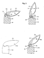
- FIG. 1 shows a cross-sectional view of the lamp according to the invention with a fixedly mounted on a wall or niche wall mounting plate 40 which is U-shaped in cross-section and in its upper leg a recess 41 and in its lower leg has a projection 42. Furthermore, a serving as a base part housing 10 is provided, which has a projection 11 in the upper region and a recess 12 in the lower region in its end region remote from the wing profile 20, by means of which the housing 10 can be inserted into the mounting profile 40. A screw connection or any other suitable connection is possible.
- the housing 10 is designed as an elongated substantially hollow executed component. In the housing 10 are the electronic components of the lamp such as the electronic ballast, which are preferably glued into the housing 10 as well as the other electronic components.
- the housing 10 has a latching element 60, which consists of elastic plastic.
- the latching element 60 is executed part-circular and has a concave surface which is provided with recesses 62.
- the latching element 60 is inserted into a corresponding recess of the housing 10.
- the housing 10 also has the bearing pin 90, which serves as a bearing for the wing profile 20.
- the wing profile 20 has in its cross section a shape which is similar to the cross-sectional view of a wing of an aircraft. On its outer side 21, the wing profile has a slightly curved surface which is approximately flush with the top of the housing 10, so that a harmonious transition between the housing 10 and the wing profile 20 results.
- the wing profile 20 has a wall 95 with a highly polished surface 100 on which the light emanating from the light source 30 is reflected.
- an acrylic cover 70 is provided which prevents contact with the hot bulb 30. This is by a simple Klippstechnik attachable and allows an unproblematic lamp replacement.
- FIG. 1 the wing profile 20 in its cross-sectional view of a tapered end.
- a latching projection 50 is provided, which is an integral part of the airfoil 20.
- the latching projection 50 can be inserted into the different recesses 62 of the latching element 60 so that preferred pivoting positions of the blade profile 20 with respect to the housing 10 result.
- four locking positions which are spaced by a pivot angle of 15 °.
- the mounting plate 40, the wing profile 20 and the housing 10 may be made of anodized aluminum.
- the cover 70 is made of transparent acrylic glass and has a disassembly aid / positioning (handle nose) for easy disassembly during lamp replacement.
- Both the wing profile 20 and the housing 10 can be closed by cover caps 110, 120 which can be plugged into the end regions.
- the cover 110 of the wing profile 20 is preferably made of a transparent material, for example made of polycarbonate.
- the covers 110, 120 may also consist of any other material, for. As aluminum, opaque plastic, etc.
- the cover 120 of the housing 10 is preferably made of non-transparent material, such as aluminum gray plastic.
- one or more locking elements are provided, which depends in particular on the length of the lamp.
- the latching projection is arranged on the bearing bush or forms part of it.
- the luminaire according to the invention can in principle also be driven or pivotable by means of a spring element with plain bearing bushing, with a friction element with plain bearing bush or with a motor drive (eg 12V motor) or also via a toothed wheel.
- a motor drive eg 12V motor
- FIG. 2 shows a further embodiment of the luminaire according to the invention.
- the locking projection 50 does not run here in recesses of a locking element, but is designed as a friction element that runs on a corresponding counter-surface 150 of the housing 10 and the pivoting movement of the airfoil 20 opposes a resistance.
- the locking projection 50 as a spring element executed, which exerts a permanent force on the part-circular running surface 150 of the housing 10.
- FIG. 2 shows the wing profile 20 in different pivoting angles.
- FIG. 2 It is further apparent that on the wing profile 20, a plain bearing bush 130 is provided which rotatably runs on the bearing journal 90.
- FIG. 3 shows a further embodiment of the luminaire according to the invention.
- the illuminant 30 is located on the wing profile 20.
- the wing profile 20 with acrylic cover 70 is performed more bulging on its underside in this embodiment.
- the acrylic cover 70 is made removable.
- a recess having a locking element 60 is provided, which is arranged on the housing 10. Arranged relative to the latching element 60 are the latching projections 50, which engage in the latching element 60, wherein due to the plurality of latching projections 50 different pivoting angles can be realized.
- the locking element is in turn designed as a projection and engages in corresponding recesses which are in communication with the sash profile 20.
- the locking projections / recesses 50 are arranged on a curved bar, which communicates with the sash profile 20 in connection and protrudes into the housing 10 in the pivoted state of the sash profile.
- FIG. 4 differs from FIG. 3 essentially in that no fluorescent tube but one or more halogen spots are used as the light source. In this case, no cover, but a shock protection 32 is provided.
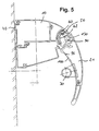
- FIG. 5 shows a cross-sectional view of an embodiment of the lamp with arranged on the housing 10 locking element 60 and arranged in the end region of the wing profile 20 locking projection 50.
- the bulb 30 is also arranged in this embodiment on the wing profile, but without the use of a cover.
- the housing 10 is attached to the fastening profile 40.
- FIG. 6 shows an embodiment in which the lighting means 30 is covered by a semicircular acrylic cover 70.
- the acrylic cover 70 has in its end regions recesses into which projections on the inside of the wing profile 20 engage.
- the luminaire holding area is also made detachable from the profile 20.
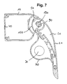
- FIG. 7 results in a further embodiment of the lamp according to the invention.
- no recesses exhibiting locking element is provided, but a sliding surface 150, on which the resiliently executed locking projection 50 runs and exerts a force on the sliding surface 150.
- the wing profile 20 can be locked or adjusted continuously in different positions.
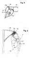
- FIG. 8 shows an embodiment of the lamp according to the invention with strongly bulging cover 70.
- the bearing pin 90 on which the airfoil 20 is rotatably mounted stands out as FIG. 8 seen through the housing 10 via.
- FIG. 9 shows a cross-sectional view of the lamp according to the invention with a substantially triangular housing 10, in the corner region of the bearing pin 90 is arranged for pivotally receiving the airfoil 20.
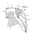
- FIG. 10 results in a further embodiment of the present invention.
- the wing profile 20 has essentially the task of producing diffused light, which is glare-free and can be regulated.
- the wing profile 20 is adjustable via the locking projection 50 and the locking element 60 in stages. It has on its inside the polished surface 100, which serves to reflect the outgoing light from the lamp 30.
- the polished surface 100 is on a wall 96 releasably connected to the profile 20.
- the wall 96 which acts as a reflector, can be locked at the same attachment points, such as the acrylic cover 70, so that the wing profile 20 can be used for cases in which the lamp 30 is disposed on the profile 20 or on the housing 10.
- FIG. 11 shows a further embodiment in which the light-emitting means 30 is arranged in the housing 10. Furthermore, a cover 160 is provided, through which the contact with the lighting means 30 is prevented.
- the wing profile 20 is relatively simple in this case. It has the curved outer surface 21 and a curved highly polished inside 100, which is located on the wall 96 and which serves as a reflector.
- the wall 96 can be replaced by a holder for the lamp 30.
- the wall 96 or the holder is detachably connected to the wing profile 20 in conjunction.
- FIG. 12 shows the light according to FIG. 11 with a fluorescent tube as the light source 30.
- FIG. 13 results in an embodiment in which the lighting means 30 is fixed to the region of the housing 10 which extends substantially parallel to the wall or to a mounting plate. Also in this embodiment, a cover 160 protects against contact of the illuminant 30.
- the wing profile 20 is designed here as a tapered on its inside and outside curved wing, which serves to reflect the emitted light.
- FIG. 14 shows an embodiment in which also the lighting means 30 is arranged behind a cover 160 on the housing 10, wherein the housing 10 in its shape slightly different from that according to FIG Fig. 13 different.
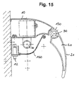
- FIG. 15 shows an embodiment with a forward in the direction of the airfoil 20 housing 10 and also preferred cover 160th Off Fig. 15 Furthermore, the switch 12 arranged at the bottom of the housing 10 can be seen.
- FIG. 16 1 also shows an embodiment with an advanced housing 10, in which the luminous means 30 is arranged behind the cover 160. Also shown is the locking element 60 with the recesses 62 disposed therein and the latching projection 50. Notwithstanding the embodiment according to FIG Fig. 1 the latching element 60 is not formed by a plastic part to be connected to the housing 10, but by the concave side of the housing 10 facing the airfoil 20. There are recesses 62 in which the latching projection 50 engages. In order to allow a relative movement between locking projection 50 and locking element 60, which is required for an adjustment of the airfoil 20, the locking projection 50 or the adjacent, this supporting end portion of the profile 20 is designed to be elastic or resilient.
- the plain bearing bush 130 of the wing profile 20 and the bearing pin 90 which is part of the housing 10.
- the reference numeral 96 indicates the insertable by a clip connection wall which forms the inner wall of the wing profile 20 and is highly polished on its outside.
- FIG. 17 results in a further embodiment in which the light-emitting means 30 is arranged in the housing 10 and has a substantially semicircular Abdekkung 160.
- the latching element 60 is shown hatched and is formed by a part-circular elastic plastic part, which is inserted into a corresponding recess of the housing 10.
- FIG. 18 shows a perspective view of the lamp according to the invention and illustrates that in a preferred embodiment of the invention, the housing 10th is designed as an elongated component. This has on its side directed towards the wing profile 20 a concave surface into which a convex end portion of the wing profile 20 engages.
- the housing 10 and the wing profile 20 have approximately the same length.
- the housing 10 and the airfoil 20 substantially independently of the pivotal position of the airfoil 20 have aligned surfaces, as is apparent from FIG. 18 evident.
- the fastening profile 40 In the end region directed to a wall can be seen the fastening profile 40, which allows easy mounting of the lamp.
- the fastening profile 40 is connected to a wall, niche wall, a board, a cheek, a wall unit, etc., preferably screwed.
- the airfoil 20 has a tapered end portion and a spaced therefrom convex, part-circular end portion. Both the outside 21 and the inside of the wing profile 20 are convex and give the wing profile a cross-sectional profile similar to that of an aircraft wing.
- wing profile 20 has a cover 110, which is transparent in contrast to the outer side 21.
- a corresponding cover is located on the other end region of the wing profile 20.
- the housing is also provided with a cover 120, which is designed as a plastic or metal part and preferably has the same color as the housing 10th
- FIGS. 19 to 32 show different arrangement options of the lamp according to the invention.
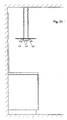
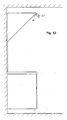
- FIG. 19 shows the arrangement of the lamp on a niche wall 200 with airfoil 20, which is arranged such that the airfoil 20 extends in the pivoted state in an area below the housing.
- FIG. 20 shows the illustration according to FIG. 19 with 180 ° turned light, which serves as a ceiling washer. If, in this embodiment, the wing profile 20 is pivoted to the niche wall, the profile 20 extends in an area above the housing 10.
- FIG. 21 shows the luminaire according to the invention in an orientation according to Fig. 19 in the upper end region of the niche wall 200.
- FIG. 22 shows the luminaire according to the invention in an orientation according to Fig. 19 on the underside of a shelf or top cabinet.
- FIG. 23 shows the lamp in an orientation according to Fig. 19 in a wall unit. Accordingly, the luminaire serves as interior lighting.
- FIG. 24 results in an embodiment in which the lamp in an orientation according to Fig. 19 attached to a support 210 which may be fixed or pivotable on a niche box.
- FIG. 25 shows the luminaire according to the invention in an orientation according to Fig. 19 in the upper end region of a vertical support element 220.
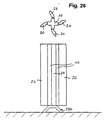
- FIG. 26 shows that with a housing 10 and a plurality of airfoils 20, in the present embodiment, four airfoils, can be combined, so that there is a to be placed on the ground by means of the foot 230 floor lamp.
- the wing profiles 20 are arranged such that the inside of a wing profile faces the outside of the adjacent wing profile.
- FIG. 27 shows one Fig. 26 in principle corresponding floor lamp with a housing 10 with two wing profiles 20 arranged thereon.
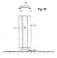
- FIG. 28 shows a corresponding embodiment with wing profiles 20, the inner sides in the swung-out state in the same direction and can be moved toward each other.
- FIG. 29 results in an arrangement of the sash profiles according to Fig. 28 in which the luminaire is a combination of two luminaires on a ceiling or in accordance with FIG. 30 on an extractor hood or according to FIG. 31 can be placed on any support which is attached to the ceiling.
- the arrangement of the bulbs towards the ceiling is possible.
- the luminaire serves as a ceiling washer in this case.
- FIG. 32 shows the lamp according to the invention finally in the front of a cooker hood.
- the lamp according to the invention may be provided with a switching element, the wing profile itself can serve as a switch for switching on or off the light, or as a safety circuit in the end position to avoid excessive heat radiation, for example, on the niche rear wall ,
- the surface of the airfoil may be smooth or textured on the outside, e.g. B. also be provided with longitudinal ribs or longitudinal grooves.
- the inside of the airfoil is preferably polished to a high gloss in parts, so that this surface takes over the task of a reflector.
- the lamp according to the invention is designed for different applications and is therefore suitable as part of a modular concept.
Description
Die vorliegende Erfindung betrifft eine Leuchte, insbesondere eine Küchenleuchte, mit einem feststehenden Basisteil, mit wenigstens einem mit dem Basisteil in Verbindung stehenden Profil, das schwenkbar an dem Basisteil befestigt ist, sowie mit wenigstens einem Leuchtmittel, das in oder an dem Basisteil oder in oder an dem Profil angeordnet ist.The present invention relates to a lamp, in particular a kitchen lamp, with a fixed base part, with at least one profile associated with the base part, which is pivotally attached to the base part, as well as with at least one light source, in or on the base part or in or is arranged on the profile.
Eine derartige Leuchte ist aus der
Es sind ferner Küchenleuchten bekannt, die aus einem Gehäuse mit fest darin eingebauten Leuchtmitteln und weiteren Bauteilen, wie beispielsweise Vorschaltgeräten, Schaltern, Leuchtmittelhaltern, Kabeln, Reflektoren sowie Abdeckungen, bestehen. Das Gehäuse besteht üblicherweise aus Blech, Kunststoff oder Aluminiumprofilen. Diese Leuchten werden in der Küche fest positioniert. Üblicherweise kommen hierfür eine Wand, eine Nischenrückwand oder eine Fläche unterhalb von Borden und Oberschränken in Frage.There are also known kitchen lights, which consist of a housing with built-in bulbs and other components, such as ballasts, switches, bulbs, cables, reflectors and covers. The housing is usually made of sheet metal, plastic or aluminum profiles. These lights are firmly positioned in the kitchen. Usually come this is a wall, a niche back wall or an area below Borden and upper cabinets in question.
Bei derartigen Leuchten besteht ein Nachteil darin, dass der Strahlwinkel der Leuchte stets konstant ist, so dass der ausgeleuchtete Bereich nicht veränderbar ist. Ein weiterer Nachteil dieser Leuchten besteht darin, dass diese nicht blendfrei ausgeführt sind.In such luminaires, a disadvantage is that the beam angle of the luminaire is always constant, so that the illuminated area is not changeable. Another disadvantage of these lights is that they are not designed glare-free.
Es ist daher die Aufgabe der vorliegenden Erfindung eine Leuchte, insbesondere eine Küchenleuchte dahingehend weiterzubilden, dass der durch die Leuchte ausgeleuchtete Bereich veränderbar ist.It is therefore the object of the present invention to further develop a lamp, in particular a kitchen lamp, in such a way that the area illuminated by the lamp can be changed.
Diese Aufgabe wird durch eine Leuchte mit den Merkmalen des Patentanspruchs 1 gelöst. Danach weist die Leuchte ein feststehendes Basisteil sowie wenigstens ein mit dem Basisteil in Verbindung stehendes Profil auf, das schwenkbar an dem Basisteil befestigt ist. Ferner ist wenigstens ein Leuchtmittel vorgesehen, dass an oder in dem Basisteil oder an oder in dem Profil angeordnet ist. Das Profil ist in seinem Querschnitt dem einer Tragfläche eines Flugzeuges angenähert. Basisteil und Profil sind erfindungsgemäß derart ausgeführt, dass ihre Oberseiten miteinander fluchten. Aufgrund des gegenüber dem Basisteil schwenkbar ausgeführten Profils kann der Leuchtwinkel und somit auch der ausgeleuchtete Bereich verändert werden. Bei entsprechender Ausführung des Profils ist darüber hinaus der Vorteil erzielbar, dass die Leuchte blendfrei arbeitet.This object is achieved by a luminaire having the features of patent claim 1. Thereafter, the lamp has a fixed base part and at least one standing with the base part in connection profile, which is pivotally mounted on the base part. Furthermore, at least one luminous means is provided which is arranged on or in the base part or on or in the profile. The profile is approximated in its cross section that of a wing of an aircraft. Base part and profile are inventively designed such that their tops are aligned. Due to the relative to the base part pivotally running profile of the beam angle and thus the illuminated area can be changed. With appropriate design of the profile beyond the advantage can be achieved that the lamp works glare-free.
Das Profil der erfindungsgemäßen Leuchte ist neben optischen Aspekten nach dem Gesichtspunkt der Lichtreflexion konzipiert, so dass die Arbeitsfläche optimal ausgeleuchtet werden kann. Es ist möglich, diffuses Licht aus direkter und indirekter Beleuchtung zur Verfügung zu stellen. Ein wesentlicher Vorteil der Leuchte besteht darin, dass das Licht auf der Arbeitsfläche je nach Tätigkeit bzw. Arbeitsplattentiefe durch Schwenken des Profils veränderbar ist. So lässt sich beispielsweise durch Zurückschwenken des Profils ein angenehmes Stimmungslicht erzeugen, indem beispielsweise nur eine Nischenrückwand angestrahlt wird. Während des Arbeitens auf der Arbeitsfläche kann das Profil entsprechend verschwenkt werden, um den Arbeitsbereich optimal auszuleuchten.The profile of the luminaire according to the invention is designed in addition to optical aspects from the viewpoint of light reflection, so that the work surface can be optimally illuminated. It is possible to provide diffused light from direct and indirect lighting. A significant advantage of the lamp is that the light on the work surface is variable depending on the activity or worktop depth by pivoting the profile. For example, by swinging back the profile a pleasant mood light can be generated, for example, by only one niche rear wall is illuminated. While working on the work surface, the profile can be swiveled to optimally illuminate the work area.
In weiterer Ausgestaltung der Erfindung ist vorgesehen, dass das Basisteil langgestreckt ist und sich das Profil in Längsrichtung des Basisteils erstreckt. Dabei ist Vorteilhafterweise vorgesehen, dass das Basisteil und das Profil im wesentlichen dieselbe Länge aufweisen.In a further embodiment of the invention, it is provided that the base part is elongate and the profile extends in the longitudinal direction of the base part. It is advantageously provided that the base part and the profile have substantially the same length.
Die Schwenkachse des Profils verläuft in bevorzugter Ausgestaltung der Erfindung in Längsrichtung des Basisteils.The pivot axis of the profile extends in a preferred embodiment of the invention in the longitudinal direction of the base part.
Weiterhin kann vorgesehen sein, dass das Basisteil an seiner zu dem Profil gewandten Seite konkav ausgeführt ist und dass das Profil an seiner zu dem Basisteil gewandten Seite konvex ausgeführt ist, wobei die konvexe Seite des Profils in den konkaven Bereich des Basisteils eingreift. Auf diese Weise wird ein besonders ansprechender optischer Eindruck der Leuchte erreicht. Dies gilt insbesondere dann, wenn der Abstand zwischen Profil und Basisteil gering ist, beispielsweise im Bereich von wenigen Millimetern oder auch darunter liegt.Furthermore, it can be provided that the base part is designed to be concave on its side facing the profile and that the profile is convex on its side facing the base part, wherein the convex side of the profile engages in the concave region of the base part. In this way, a particularly appealing visual impression of the lamp is achieved. This is especially true when the distance between the profile and the base part is small, for example in the range of a few millimeters or even less.
Ein besonders ansprechender optischer Gesamteindruck ergibt sich erfindungsgemäß dadurch, dass die Oberseite des Basisteils sowie die Oberseite des Profils im wesentlichen miteinander fluchten. In vorteilhafter Ausgestaltung der Erfindung gilt dies unabhängig vom Schwenkwinkel des Profils.A particularly appealing overall visual impression results according to the invention in that the upper side of the base part and the upper side of the profile are substantially aligned with one another. In an advantageous embodiment of the invention, this applies regardless of the tilt angle of the profile.
Gemäß der vorliegenden Erfindung ist vorgesehen, dass das Profil in seinem Querschnitt dem einer Tragfläche eines Flugzeugs entspricht.According to the present invention it is provided that the profile in its cross section corresponds to that of a wing of an aircraft.
In weiterer Ausgestaltung der vorliegenden Erfindung ist vorgesehen, dass das Profil gegenüber dem Basisteil stufenlos verstellbar ist oder in Vorzugsstellungen arretierbar ist. Im letzten Fall kann vorgesehen sein, dass ein Rastelement vorgesehen ist, das auf seiner Oberseite Einwölbungen oder Einkerbungen aufweist, und dass ein Rastvorsprung vorgesehen ist, der in die Einwölbungen oder Einkerbungen eingreift.In a further embodiment of the present invention, it is provided that the profile relative to the base part is continuously adjustable or can be locked in preferred positions. In the latter case it can be provided that a latching element is provided which has concavities or indentations on its upper side, and that a locking projection is provided which engages in the indentations or indentations.
Dabei kann vorgesehen sein, dass das Rastelement und/oder der Rastvorsprung elastisch ausgeführt sind. Als geeignetes Material kommt beispielsweise elastischer Kunststoff in Frage. Auch beliebige andere Materialien sind einsetzbar. Denkbar ist beispielsweise, den Rastvorsprung als federndes Element vorzusehen, wobei dieser z.B. aus Kunststoff oder aus Metall bestehen kann.It can be provided that the latching element and / or the latching projection are designed to be elastic. As a suitable material is for example elastic plastic in question. Any other materials can be used. It is conceivable, for example, to provide the locking projection as a resilient element, which may for example consist of plastic or metal.
Besonders vorteilhaft ist es, wenn der Rastvorsprung an einem Endbereich des Profils angeordnet ist oder durch diesen gebildet wird. Beispielsweise kann der Rastvorsprung durch den in Querrichtung des Profils zu dem Basisteil gewandten Endbereich des Profils gebildet werden. Der Rastvorsprung kann in diesem Fall beispielsweise mit einem Rastelement zusammenwirken, das aus elastischem Kunststoff oder einem sonstigen elastischen Material ausgeführt ist und fest in dem Basisteil angeordnet ist.It is particularly advantageous if the latching projection is arranged on an end region of the profile or is formed by it. For example, the latching projection can be formed by the end region of the profile which faces the base part in the transverse direction of the profile. The locking projection can cooperate in this case, for example, with a locking element, which is made of elastic plastic or other elastic material and is fixedly arranged in the base part.
Selbstverständlich ist es ebenso denkbar, dass nicht das Rastelement, sondern der Rastvorsprung elastisch ausgeführt ist.Of course, it is also conceivable that not the locking element, but the latching projection is designed to be elastic.
Vorteilhaft ist es, wenn das Rastelement austauschbar ist, so dass je nach Bedarf unterschiedliche Schwenkwinkel als Vorzugspositionen eingestellt werden können.It is advantageous if the latching element is exchangeable, so that different pivoting angles can be set as preferred positions as required.
In bevorzugter Ausgestaltung der vorliegenden Erfindung ist vorgesehen, dass das Profil eine Lagerbuchse aufweist, die gegenüber einem Lager des Basisteils drehbar ist. Dabei kann vorgesehen sein, dass das Lager durch eine Stiftschraube oder einen Zapfen gebildet wird, die/der verdrehfest an dem Basisteil angeordnet ist. Die Lagerbuchse läuft entsprechend einem Gleitlager auf dem verdrehfest angeordneten Lager und ermöglicht auf diese Weise die schwenkbare Ausführung des Profils.In a preferred embodiment of the present invention it is provided that the profile has a bearing bush which is rotatable relative to a bearing of the base part. It can be provided that the bearing is formed by a stud or a pin, which is arranged rotationally fixed to the base part. The bushing runs according to a plain bearing on the rotationally fixed bearing and allows in this way the pivotal design of the profile.
In weiterer Ausgestaltung der vorliegenden Erfindung ist vorgesehen, dass die elektrischen Bauteile der Leuchte, beispielsweise ein Vorschaltgerät, in dem Basisteil angeordnet sind. Auch beliebige andere elektrische Bauteile können in dem Basisteil angeordnet sein. Dies gilt beispielsweise für Steckdosen, Lichtschalter sowie für Sensoren für die Fernsteuerung und Dimmgeräte oder Anschlüsse für BUS-Systeme.In a further embodiment of the present invention, it is provided that the electrical components of the lamp, such as a ballast, are arranged in the base part. Any other electrical components may be arranged in the base part. This applies, for example, to sockets, light switches and sensors for remote control and dimming devices or connections for BUS systems.
Gemäß einer bevorzugten Ausgestaltung der Erfindung ist ein Befestigungsprofil vorgesehen, mit dem das Basisteil verbindbar ist. Auf diese Weise ist die Leuchte sehr einfach montierbar. Sie wird auf einem Befestigungsprofil beispielsweise aufgeklippst oder aufgeschraubt. Auch andere Befestigungsmöglichkeiten sind denkbar. Das Befestigungsprofil kann beispielsweise an einer Wand oder Nischenwand oder an einem Bord oder an oder in einem Schrank montiert sein. Die Verwendung eines Befestigungsprofils ermöglicht auch eine einfache Elektroinstallation der Leuchte. Das Befestigungsprofil kann als flache Schiene ausgeführt sein, die Ausnehmungen und/oder Vorsprünge aufweist, in die Vorsprünge und/oder Ausnehmungen des Profils einfügbar sind.According to a preferred embodiment of the invention, a fastening profile is provided, with which the base part is connectable. In this way, the lamp is very easy to install. It is clipped on a fastening profile, for example or screwed on. Other mounting options are conceivable. The fastening profile can be mounted, for example, on a wall or niche wall or on a shelf or on or in a cabinet. The use of a mounting profile also allows easy electrical installation of the lamp. The fastening profile may be designed as a flat rail having recesses and / or projections, in which projections and / or recesses of the profile can be inserted.
Ist das Basisteil als Hohlkörper ausgeführt, ergibt sich eine besonders einfache Elektroinstallation der Leuchte.If the base part designed as a hollow body, there is a particularly simple electrical installation of the lamp.
Das Basisteil wird auf einer Seite durch das Befestigungsprofil abgedeckt und kann in den Seitenbereichen ebenfalls über Abdeckungen verfügen.The base part is covered on one side by the fastening profile and can also have covers in the side areas.
Weiterhin kann vorgesehen sein, dass das Profil auf seiner Innenseite wenigstens teilweise hochglanzpoliert ist, so dass diese Fläche die Aufgabe eines Reflektors übernimmt, ohne dass ein zusätzliches Bauteil benötigt wird.Furthermore, it can be provided that the profile is at least partially highly polished on its inside, so that this area takes on the task of a reflector, without an additional component is needed.
In weiterer Ausgestaltung der Erfindung ist vorgesehen, dass das Profil eine transparente Abdeckung aufweist, die den die Leuchte aufnehmenden Bereich überdeckt und als Berührschutz dient. Hierfür kommt beispielsweise eine Acrylabdekkung in Frage. Die Abdeckung verhindert den Kontakt zu den heißen Leuchtmitteln und ermöglicht durch eine einfach Klippstechnik den unproblematischen Lampenwechsel.In a further embodiment of the invention, it is provided that the profile has a transparent cover, which covers the area receiving the luminaire and serves as contact protection. For this purpose, for example, a Acrylabdekkung in question. The cover prevents contact with the hot light bulbs and allows a simple clip technique the unproblematic lamp replacement.
Das Basisteil kann als Gehäuse ausführt sein.The base part can be designed as a housing.
Weitere Einzelheiten und Vorteile der Erfindung werden an Hand eines in der Zeichnung dargestellten Ausführungsbeispiels erläutert. Es zeigen:
- Figuren 1 - 10:
- Querschnittsansichten von erfindungsgemäßen Leuchten mit an dem Profil angeordneten Leuchtmitteln,
- Figuren 11 - 17:
- Querschnittsansichten von erfindungsgemäßen Leuchten mit an dem als Gehäuse ausgeführten Basisteil angeordneten Leuchtmitteln,
- Figur 18:
- eine perspektivische Darstellung der erfindungsgemäßen Leuchte und
- Figuren 19 - 32:
- schematische Darstellungen unterschiedlicher Anordnungsmöglichkeiten der erfindungsgemäßen Leuchte.
- Figures 1 - 10:
- Cross-sectional views of lights according to the invention with arranged on the profile bulbs,
- Figures 11-17:
- Cross-sectional views of lights according to the invention with arranged on the housing designed as a base bulbs,
- FIG. 18:
- a perspective view of the lamp according to the invention and
- Figures 19-32:
- schematic representations of different arrangement options of the lamp according to the invention.
In dem von der Befestigungsplatte 40 abgewandten Bereich weist das Gehäuse 10 ein Rastelement 60 auf, das aus elastischem Kunststoff besteht. Das Rastelement 60 ist teilkreisförmig ausgeführt und weist eine konkave Oberfläche auf, die mit Ausnehmungen 62 versehen ist. Das Rastelement 60 ist in eine entsprechende Ausnehmung des Gehäuses 10 eingesetzt.In the area facing away from the mounting
Das Gehäuse 10 weist ferner den Lagerzapfen 90 auf, der als Lager für das Flügelprofil 20 dient.The
Das Flügelprofil 20 weist in seinem Querschnitt eine Form auf, die der Querschnittsansicht einer Tragfläche eines Flugzeugs ähnelt. Auf seiner Außenseite 21 weist das Flügelprofil eine leicht gekrümmte Oberfläche auf, die in etwa mit der Oberseite des Gehäuses 10 fluchtet, so dass sich ein harmonischer Übergang zwischen Gehäuse 10 und Flügelprofil 20 ergibt.The
Das Flügelprofil 20 weist eine Wandung 95 mit einer hochglanzpolierten Oberfläche 100 auf, auf der das von dem Leuchtmittel 30 ausgehende Licht reflektiert wird.The
Des weiteren ist eine Acrylabdeckung 70 vorgesehen, die den Kontakt zu dem hei-ßen Leuchtmittel 30 verhindert. Diese ist durch eine einfache Klippstechnik ansteckbar und ermöglicht einen unproblematischen Lampenwechsel.Furthermore, an
Wie aus
Auf dem Lagerzapfen 90 läuft eine Buchse des Flügelprofils 20.On the bearing pin 90 a bushing of the
Die Befestigungsplatte 40, das Flügelprofil 20 sowie das Gehäuse 10 können aus eloxiertem Aluminium hergestellt sein.The mounting
Die Abdeckung 70 besteht aus Transparentem Acrylglas und weist eine Demontagehilfe/Positionierhilfe (Griffnase) für die einfache Demontage bei Lampenwechsel auf.The
Sowohl das Flügelprofil 20 als auch das Gehäuse 10 sind durch in den Endbereichen aufsteckbare Abdeckkappen 110, 120 verschließbar. Dabei ist die Abdeckung 110 des Flügelprofils 20 vorzugsweise aus einem transparenten Material, beispielsweise aus Polycarbonat ausgeführt. Die Abdeckkappen 110, 120 können aber auch aus jedem beliebigen anderen Material bestehen, z. B. Aluminium, opakem Kunststoff etc. Die Abdeckung 120 des Gehäuses 10 ist vorzugsweise aus nicht transparentem Material, beispielsweise aus aluminiumgrauen Kunststoff ausgeführt.Both the
Es kann vorgesehen sein, dass ein oder mehrere Rastelemente vorgesehen sind, was insbesondere von der Leuchtenlänge abhängt.It can be provided that one or more locking elements are provided, which depends in particular on the length of the lamp.
Ferner kann vorgesehen sein, dass der Rastvorsprung auf der Lagerbuchse angeordnet ist oder deren Bestandteil bildet.Furthermore, it can be provided that the latching projection is arranged on the bearing bush or forms part of it.
Neben der dargestellten Arretierungsmöglichkeit mittels Rastelement und Rastvorsprung kann die erfindungsgemäßen Leuchte grundsätzlich auch mit einem Federelement mit Gleitlagerbuchse, mit einem Reibelement mit Gleitlagerbuchse oder auch mit einem Motorantrieb (z. B. 12V Motor) oder auch über ein Zahnrad angetrieben bzw. verschwenkbar sein.In addition to the illustrated locking possibility by means of locking element and locking projection, the luminaire according to the invention can in principle also be driven or pivotable by means of a spring element with plain bearing bushing, with a friction element with plain bearing bush or with a motor drive (eg 12V motor) or also via a toothed wheel.
Aus
Abweichend davon ist es ebenso möglich, dass das Rastelement seinerseits als Vorsprung ausgeführt ist und in entsprechende Rastausnehmungen eingreift, die mit dem Flügelprofil 20 in Verbindung stehen.Deviating from this, it is also possible that the locking element is in turn designed as a projection and engages in corresponding recesses which are in communication with the
Wie aus
Aus
Aus
Das Flügelprofil 20 ist über den Rastvorsprung 50 und das Rastelement 60 in Stufen verstellbar. Es weist auf seiner Innenseite die polierte Oberfläche 100 auf, die zur Reflexion des von dem Leuchtmittel 30 ausgehenden Lichts dient. Die polierte Oberfläche 100 befindet sich auf einer Wandung 96, die lösbar mit dem Profil 20 in Verbindung steht. Wie ein Vergleich der
Aus
In
Aus
Das Flügelprofil 20 weist einen spitz zulaufenden Endbereich und einen davon beabstandeten konvexen, teilkreisförmigen Endbereich auf. Sowohl die Außenseite 21 als auch die Innenseite des Flügelprofils 20 sind konvex ausgeführt und geben dem Flügelprofil ein Querschnittsprofil ähnlich dem eines Flugzeugflügels.The
Aus
Das Gehäuse ist ebenfalls mit einer Abdeckung 120 versehen, die als Kunststoff- oder Metallteil ausgeführt ist und vorzugsweise dieselbe Farbe aufweist, wie das Gehäuse 10.The housing is also provided with a
Die
Aus
Aus
Aus
Auch die Anordnung der Leuchtmittel zur Decke hin ist möglich. Die Leuchte dient in diesem Fall als Deckenfluter.The arrangement of the bulbs towards the ceiling is possible. The luminaire serves as a ceiling washer in this case.
Ergänzend ist darauf hinzuweisen, dass die erfindungsgemäße Leuchte mit einem Schaltelement versehen sein kann, wobei das Flügelprofil selbst als Schalter für die Ein- bzw. Ausschaltung des Lichts dienen kann, bzw. als Sicherheitsschaltung in Endstellung um zu große Wärmestrahlung beispielsweise auf die Nischenrückwand zu vermeiden. Die Oberfläche des Flügelprofils kann Außen glatt oder strukturiert sein, z. B. auch mit Längsrippen oder Längsrillen versehen sein. Die Innenseite des Flügelprofils ist vorzugsweise in Teilbereichten hochglanzpoliert, so dass diese Fläche die Aufgabe eines Reflektors übernimmt.In addition, it should be noted that the lamp according to the invention may be provided with a switching element, the wing profile itself can serve as a switch for switching on or off the light, or as a safety circuit in the end position to avoid excessive heat radiation, for example, on the niche rear wall , The surface of the airfoil may be smooth or textured on the outside, e.g. B. also be provided with longitudinal ribs or longitudinal grooves. The inside of the airfoil is preferably polished to a high gloss in parts, so that this surface takes over the task of a reflector.
Die erfindungsgemäße Leuchte ist für unterschiedliche Anwendungsmöglichkeiten konzipiert und eignet sich dementsprechend als Bestandteil eines Baukastenkonzepts. The lamp according to the invention is designed for different applications and is therefore suitable as part of a modular concept.
Claims (14)
- Luminaire, particularly a kitchen luminaire, having a fixed base part (10), at least one profile (20) communicating with the base part (10), which is pivotably attached to the base part (10), and at least one bulb or lamp (30) which is arranged within or at the base part (10) or within or at the profile (20),
characterised in that
the upper face of the base part (10) as well as the upper face of the profile (20) are substantially aligned with each other and in that the profile (20) in its cross-section approximates the aerofoil of an aeroplane,
in that the base part (10), on its face opposite the profile (20), is realised in a concave shape and in that the profile (20), on its face opposite the base part (10), is realised in a convex shape, wherein the convex face of the profile (20) engages in the concave portion of the base part (10). - Luminaire according to claim 1, characterised in that the base part (10) has a longitudinal shape and that the profile (20) extends in the longitudinal direction of the base part (10).
- Luminaire according to claim 2, characterised in that the base part (10) and the profile (20) substantially have the same length.
- Luminaire according to claim 2 or 3, characterised in that the pivot axis of the profile (20) extends in parallel to the longitudinal direction of the base part (10).
- Luminaire according to any one of the preceding claims, characterised in that the profile (20) is continuously adjustable with respect to the base part (10) or is lockable in a preferred position.
- Luminaire according to claim 5, characterised in that a detent element (60) is provided which has vault-like dents or notches (62) on its upper face and in that a detent projection (50) is provided which engages in the vault-like dents or notches (62).
- Luminaire according to any one of the preceding claims, characterised in that the detent element and/or the detent projection (50) is realised in an elastic manner.
- Luminaire according to claim 6 or 7, characterised in that the detent projection (50) is arranged at an end portion of the profile (20) or is formed by the same.
- Luminaire according to any one of the preceding claims, characterised in that the profile (20) comprises a bearing sleeve which is rotable with respect to the base part (10).
- Luminaire according to claim 9, characterised in that the bearing is formed by a screw or a journal (90).
- Luminaire according to any one of the preceding claims, characterised in that the electric components of the luminaire are arranged within the base part (10).
- Luminaire according to any one of the preceding claims, characterised in that a mounting profile (40) is provided to which, for the purpose of mounting the luminaire, the base part (10) is connectable.
- Luminaire according to any one of the preceding claims, characterised in that the profile (20) is at least partly mirror-finished on its inner face.
- Luminaire according to any one of the preceding claims, characterised in that the profile (20) and/or the base part (10) comprises a transparent cover (70) of the portion accommodating the luminaire.
Applications Claiming Priority (2)
| Application Number | Priority Date | Filing Date | Title |
|---|---|---|---|
| DE10343533 | 2003-09-19 | ||
| DE10343533A DE10343533B4 (en) | 2003-09-19 | 2003-09-19 | lamp |
Publications (3)
| Publication Number | Publication Date |
|---|---|
| EP1517080A2 EP1517080A2 (en) | 2005-03-23 |
| EP1517080A3 EP1517080A3 (en) | 2005-11-16 |
| EP1517080B1 true EP1517080B1 (en) | 2008-04-16 |
Family
ID=34177851
Family Applications (1)
| Application Number | Title | Priority Date | Filing Date |
|---|---|---|---|
| EP04021952A Active EP1517080B1 (en) | 2003-09-19 | 2004-09-15 | Luminaire |
Country Status (2)
| Country | Link |
|---|---|
| EP (1) | EP1517080B1 (en) |
| DE (2) | DE10343533B4 (en) |
Families Citing this family (13)
| Publication number | Priority date | Publication date | Assignee | Title |
|---|---|---|---|---|
| DE202005010313U1 (en) * | 2005-06-30 | 2006-11-23 | Ilt Gmbh International Lighting Technologies | Floor lamp with lamp head |
| DE102005031173B4 (en) * | 2005-07-04 | 2008-04-30 | Siteco Beleuchtungstechnik Gmbh | Lamp with swivel device |
| DE102006041582A1 (en) * | 2006-09-05 | 2008-03-06 | BSH Bosch und Siemens Hausgeräte GmbH | Extractor hood for stove in cooking area, has moisture shield with horizontally extending central unit and wing provided at external side of unit, and illuminant provided in wing that is pivotably and movably connected with central unit |
| DE102009045961A1 (en) * | 2009-10-23 | 2011-04-28 | BSH Bosch und Siemens Hausgeräte GmbH | Lighting device for a kitchen work surface and kitchen element with a kitchen work surface and at least one lighting device |
| DE102010004352B4 (en) * | 2010-01-06 | 2016-09-08 | Teka Industrial S.A. | kitchen arrangement |
| DE102010006330A1 (en) * | 2010-01-29 | 2011-08-04 | GRAH Automotive d.o.o. | Pole attachment for attaching a luminaire body to a luminaire pole |
| DE102010040509A1 (en) * | 2010-09-09 | 2012-03-15 | BSH Bosch und Siemens Hausgeräte GmbH | Hood |
| US8789967B2 (en) | 2011-06-02 | 2014-07-29 | Musco Corporation | Apparatus, method, and system for independent aiming and cutoff steps in illuminating a target area |
| DE102011052582A1 (en) * | 2011-08-11 | 2013-02-14 | Hella Kgaa Hueck & Co. | outdoor light |
| DE102012205237B4 (en) * | 2012-03-30 | 2019-11-28 | Andreas Hierzer | Luminaire for use in a lighting arrangement |
| DE102013203103B4 (en) * | 2013-02-26 | 2018-05-09 | Osram Gmbh | Fixing element for a lighting device |
| US11149925B2 (en) | 2016-06-09 | 2021-10-19 | Signify Holding B.V. | Lighting device including adjustable cover |
| DE102017101784A1 (en) | 2017-01-30 | 2018-08-02 | Osram Gmbh | Variable adjustable quick-fastening system for luminaires on mast flanges |
Family Cites Families (8)
| Publication number | Priority date | Publication date | Assignee | Title |
|---|---|---|---|---|
| US2740885A (en) * | 1951-06-25 | 1956-04-03 | A L Smith Iron Company | Adjustable fluorescent light fixture |
| DE7719975U1 (en) * | 1977-06-25 | 1977-10-13 | Luederitz, Willi, Dipl.-Ing., 4990 Luebbecke | WALL LAMP, ESPECIALLY FOR HOSPITAL ROOM |
| DE4303185A1 (en) * | 1992-03-17 | 1993-09-23 | Zumtobel Licht | Hinged holder e.g. for wall- or ceiling-mounted lamp - Has bracket for lamp which can tilt through plus or minus 10 deg on parallel ribs with attachment screws limiting movement |
| US5564815A (en) * | 1994-06-29 | 1996-10-15 | Lightron Of Cornwall Incorporated | Adjustable light fixture |
| DE29503526U1 (en) * | 1995-03-03 | 1995-05-04 | Jokey Plastik Sohland Gmbh | Luminaire carriers, especially for recessed lights |
| DE19917283A1 (en) * | 1999-04-17 | 2000-10-19 | Licona Leuchten Gmbh | Light has tubular basic body with two half shells with rounded grooves on longitudinal edges with which half-shells can be joined in shape-locking manner, pivoted about one long edge |
| WO2001007832A1 (en) * | 1999-07-27 | 2001-02-01 | Steffen Ritter | Lamp with rotatably mounted reflector support |
| DE10321282B4 (en) * | 2003-05-13 | 2010-11-25 | Trilux Gmbh & Co. Kg | wall light |
-
2003
- 2003-09-19 DE DE10343533A patent/DE10343533B4/en not_active Expired - Fee Related
-
2004
- 2004-09-15 EP EP04021952A patent/EP1517080B1/en active Active
- 2004-09-15 DE DE502004006825T patent/DE502004006825D1/en active Active
Also Published As
| Publication number | Publication date |
|---|---|
| DE502004006825D1 (en) | 2008-05-29 |
| EP1517080A2 (en) | 2005-03-23 |
| DE10343533A1 (en) | 2005-05-04 |
| EP1517080A3 (en) | 2005-11-16 |
| DE10343533B4 (en) | 2007-08-09 |
Similar Documents
| Publication | Publication Date | Title |
|---|---|---|
| EP1517080B1 (en) | Luminaire | |
| EP0898686B2 (en) | Lighting fitting with a basic unit as support for at least one lamp | |
| WO2012056029A1 (en) | Wall border strip for lighting a work panel | |
| DE102009007308A1 (en) | Surface or wall light | |
| EP2071227A1 (en) | Wall- or ceiling lamp | |
| DE10310330A1 (en) | Refrigerator or freezer with internal lighting has at least one light body for illuminating interior volume of refrigerator or freezer attached to inside of door facing interior volume. | |
| EP1248033A2 (en) | Reflector lamp, especially floor-, ceiling- or wall-reflector lamp of the recessed type | |
| EP1537357B1 (en) | Fitted kitchen element | |
| EP1656527B1 (en) | Refrigerator with interior lighting | |
| DE202012100901U1 (en) | recessed light | |
| DE202010001579U1 (en) | Lighting device for a movable furniture element and furniture element | |
| DE102014000558B3 (en) | Floor lamp with bifunctional head | |
| EP1035369B1 (en) | Lighting system | |
| DE102009045961A1 (en) | Lighting device for a kitchen work surface and kitchen element with a kitchen work surface and at least one lighting device | |
| DE2812090A1 (en) | Light fitting for internal reflector lamps - has swivelling rod for adjusting external reflector on lamp base | |
| DE102008018128B4 (en) | cabinet furniture | |
| EP2208192B1 (en) | Pictogram lamp | |
| EP1956325A2 (en) | Refrigeration and/or freezer device | |
| DE102006005290A1 (en) | Lighting assembly for a household appliance | |
| WO2011020915A1 (en) | Lighting unit that can be fixed without tools | |
| EP1145663B1 (en) | Vanity mirror | |
| EP1477725A2 (en) | Wall-mounted luminaire | |
| EP2813753B1 (en) | Lamp | |
| DE102004058241A1 (en) | Lamp e.g. emitter, for lighting of surfaces and articles, has carrier part swiveling supported around diametrically running axis in intermediate ring and rotatably supported in guidance and retaining admissions around housing axis | |
| DE202010003283U1 (en) | Device for illuminating a worktop |
Legal Events
| Date | Code | Title | Description |
|---|---|---|---|
| PUAI | Public reference made under article 153(3) epc to a published international application that has entered the european phase |
Free format text: ORIGINAL CODE: 0009012 |
|
| AK | Designated contracting states |
Kind code of ref document: A2 Designated state(s): AT BE BG CH CY CZ DE DK EE ES FI FR GB GR HU IE IT LI LU MC NL PL PT RO SE SI SK TR |
|
| AX | Request for extension of the european patent |
Extension state: AL HR LT LV MK |
|
| PUAL | Search report despatched |
Free format text: ORIGINAL CODE: 0009013 |
|
| AK | Designated contracting states |
Kind code of ref document: A3 Designated state(s): AT BE BG CH CY CZ DE DK EE ES FI FR GB GR HU IE IT LI LU MC NL PL PT RO SE SI SK TR |
|
| AX | Request for extension of the european patent |
Extension state: AL HR LT LV MK |
|
| 17P | Request for examination filed |
Effective date: 20060207 |
|
| AKX | Designation fees paid |
Designated state(s): CH DE FR IT LI |
|
| 17Q | First examination report despatched |
Effective date: 20060411 |
|
| GRAP | Despatch of communication of intention to grant a patent |
Free format text: ORIGINAL CODE: EPIDOSNIGR1 |
|
| GRAS | Grant fee paid |
Free format text: ORIGINAL CODE: EPIDOSNIGR3 |
|
| GRAA | (expected) grant |
Free format text: ORIGINAL CODE: 0009210 |
|
| AK | Designated contracting states |
Kind code of ref document: B1 Designated state(s): CH DE FR IT LI |
|
| REG | Reference to a national code |
Ref country code: CH Ref legal event code: NV Representative=s name: BOVARD AG PATENTANWAELTE Ref country code: CH Ref legal event code: EP |
|
| REF | Corresponds to: |
Ref document number: 502004006825 Country of ref document: DE Date of ref document: 20080529 Kind code of ref document: P |
|
| ET | Fr: translation filed | ||
| PLBE | No opposition filed within time limit |
Free format text: ORIGINAL CODE: 0009261 |
|
| STAA | Information on the status of an ep patent application or granted ep patent |
Free format text: STATUS: NO OPPOSITION FILED WITHIN TIME LIMIT |
|
| 26N | No opposition filed |
Effective date: 20090119 |
|
| PGFP | Annual fee paid to national office [announced via postgrant information from national office to epo] |
Ref country code: CH Payment date: 20090923 Year of fee payment: 6 |
|
| REG | Reference to a national code |
Ref country code: CH Ref legal event code: PFA Owner name: BULTHAUP GMBH & CO KG Free format text: BULTHAUP GMBH & CO KG#WERKSTRASSE 6#84155 BODENKIRCHEN (DE) -TRANSFER TO- BULTHAUP GMBH & CO KG#WERKSTRASSE 6#84155 BODENKIRCHEN (DE) |
|
| REG | Reference to a national code |
Ref country code: CH Ref legal event code: PL |
|
| REG | Reference to a national code |
Ref country code: FR Ref legal event code: ST Effective date: 20110531 |
|
| PG25 | Lapsed in a contracting state [announced via postgrant information from national office to epo] |
Ref country code: CH Free format text: LAPSE BECAUSE OF NON-PAYMENT OF DUE FEES Effective date: 20100930 Ref country code: LI Free format text: LAPSE BECAUSE OF NON-PAYMENT OF DUE FEES Effective date: 20100930 Ref country code: FR Free format text: LAPSE BECAUSE OF NON-PAYMENT OF DUE FEES Effective date: 20100930 |
|
| PGFP | Annual fee paid to national office [announced via postgrant information from national office to epo] |
Ref country code: FR Payment date: 20091005 Year of fee payment: 6 |
|
| REG | Reference to a national code |
Ref country code: DE Ref legal event code: R082 Ref document number: 502004006825 Country of ref document: DE Representative=s name: KLUNKER IP PATENTANWAELTE PARTG MBB, DE |
|
| PGFP | Annual fee paid to national office [announced via postgrant information from national office to epo] |
Ref country code: IT Payment date: 20220930 Year of fee payment: 19 Ref country code: DE Payment date: 20221114 Year of fee payment: 19 |