EP1516945A2 - Textilmaschine mit Absaugeinrichtung - Google Patents
Textilmaschine mit Absaugeinrichtung Download PDFInfo
- Publication number
- EP1516945A2 EP1516945A2 EP04016834A EP04016834A EP1516945A2 EP 1516945 A2 EP1516945 A2 EP 1516945A2 EP 04016834 A EP04016834 A EP 04016834A EP 04016834 A EP04016834 A EP 04016834A EP 1516945 A2 EP1516945 A2 EP 1516945A2
- Authority
- EP
- European Patent Office
- Prior art keywords
- filter
- suction device
- textile machine
- cone
- machine
- Prior art date
- Legal status (The legal status is an assumption and is not a legal conclusion. Google has not performed a legal analysis and makes no representation as to the accuracy of the status listed.)
- Withdrawn
Links
Images
Classifications
-
- D—TEXTILES; PAPER
- D01—NATURAL OR MAN-MADE THREADS OR FIBRES; SPINNING
- D01H—SPINNING OR TWISTING
- D01H11/00—Arrangements for confining or removing dust, fly or the like
- D01H11/005—Arrangements for confining or removing dust, fly or the like with blowing and/or suction devices
Definitions
- the present invention relates to a textile machine with a suction according to the independent claim.
- a big problem in every spinning plant is the textile material, which is in every case individual of the processes required for yarn production is released and in the form of smaller or larger particles first hovering in the air, only to then on each one to set up a conceivable place.
- the breath and Machine functions equally affected, as far as possible contain, are suction for the whole spinning as well as such provided for the single machine.
- a suction device for a single textile machine is described in DE 199 51 235 described on the one hand as the closest prior art, on the other hand to be an integral part of the present application.
- Air is from the interior of a cone filter on the one hand in a suction chamber and further supplied to a negative pressure source, while on the other hand, a partial air amount in enters a filter room and from there on at least a filter and a suction line also passes to the vacuum source.
- one filter and another Filter be cleaned by reversing the air as a result of opening flaps, wherein Waste from the primary filter also enters a collecting space.
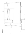
- the primary filter chamber 1 shows schematically a part of a textile machine 3 with a primary 1 and a secondary filter chamber 2.
- the primary filter chamber 1 is the primary filter 4 in its inventive design, namely in the form of a Double cone or at least in the form of a cone, which at its tapered end in a cylinder opens.
- a secondary filter 5 here in the form of a filter bag. This clever arrangement causes the primary filter 4 is virtually self-cleaning and remains of dirt by means of Removable filter bag 5 completely collected and by the operator can be easily disposed of.
- the primary filter 4 is made of air-permeable, preferably made of textile material, so that dirt particles, the pressure on the Extractor be transported through the filter 4, located on its walls can deposit.
- This filter 4 is preferably by a respective form and / or non-positive connection to the walls of the housing, so the primary Airspace 1, mounted so that it in the case of constipation or wear very easy to dismantle and disassemble.
- Particularly relevant is the form of the Filters 4. If it has the shape of an ordinary cone, it tends to blockage in the Area of the smallest diameter, so at its connection to the secondary Filter room 2, when said secondary filter room 2 is cleaned manually.
- this cone is on the Narrow side at least one cylinder, preferably an opposite cone in Downstream fiber fly, the tendency to clog completely remedy.
- the removal of the outlet, which passes through the filter 4 and enters the secondary filter chamber 2 can be designed in various ways.
- DE 199 51 235 it is provided that operators disposed of the departure manually. This brings in addition to the less pleasant, because dusty, handling possibly also a loss of production with it, since the machine stands as long as the dirt material can not be removed continuously.
- a secondary filter 5 can be suspended in the filter chamber 2 in the form of a filter bag, in which the remaining outlet is collected and compressed.
- an intermittent vacuum source 7 may be identical to or connected to the already existing in a spinning suction device; but it can also be a separate device for the machine or for a machine group of the same or not the same type.
Landscapes
- Engineering & Computer Science (AREA)
- Mechanical Engineering (AREA)
- Textile Engineering (AREA)
- Spinning Or Twisting Of Yarns (AREA)
- Filtering Of Dispersed Particles In Gases (AREA)
- Preliminary Treatment Of Fibers (AREA)
Abstract
Description
Zum zweiten ist es möglich, den sekundären Filterraum an eine intermittierende Unterdruckquelle 7 anzuschliessen. Diese Unterdruckquelle kann identisch sein mit der oder angeschlossen sein an die in einer Spinnerei bereits vorhandene Absaugeinrichtung; sie kann aber auch eine eigene Vorrichtung für die Maschine oder für eine Maschinengruppe gleichen oder nicht gleichen Typs sein.
Claims (5)
- Textilmaschine (3) mit einer Absaugeinrichtung, dadurch gekennzeichnet, dass diese einen Filter (4) enthält, der die Form eines Doppelkonus' hat oder zumindest die Form eines Konus' mit aufgesetztem Zylinder.
- Textilmaschine mit einer Absaugeinrichtung nach Anspruch 1, dadurch gekennzeichnet, dass sie weiteren einen Filter (5) in Form eines Filtersackes enthält.
- Textilmaschine mit einer Absaugeinrichtung nach Anspruch 1, dadurch gekennzeichnet, dass sie einen Filterraum (1,2) enthält, der über eine Druckbeaufschlagungsquelle (7) gereinigt wird.
- Textilmaschine mit einer Absaugeinrichtung nach Anspruch 3, dadurch gekennzeichnet, dass als Druckbeaufschlagungsquelle (7) eine spinnereieigene Druckbeaufschlagungsquelle vorgesehen ist.
- Textilmaschine mit einer Absaugeinrichtung nach Anspruch 1, dadurch gekennzeichnet, dass Druckbeaufschlagungsquelle (7) eine separate Druckbeaufschlagungsquelle für die Textilmaschine (3) oder eine Gruppe von Textilmaschinen vorgesehen ist.
Applications Claiming Priority (2)
| Application Number | Priority Date | Filing Date | Title |
|---|---|---|---|
| CH16742003 | 2003-09-18 | ||
| CH16742003 | 2003-09-18 |
Publications (2)
| Publication Number | Publication Date |
|---|---|
| EP1516945A2 true EP1516945A2 (de) | 2005-03-23 |
| EP1516945A3 EP1516945A3 (de) | 2006-03-22 |
Family
ID=34140511
Family Applications (1)
| Application Number | Title | Priority Date | Filing Date |
|---|---|---|---|
| EP04016834A Withdrawn EP1516945A3 (de) | 2003-09-18 | 2004-07-16 | Textilmaschine mit Absaugeinrichtung |
Country Status (3)
| Country | Link |
|---|---|
| EP (1) | EP1516945A3 (de) |
| JP (1) | JP2005089958A (de) |
| CN (1) | CN1598100A (de) |
Families Citing this family (3)
| Publication number | Priority date | Publication date | Assignee | Title |
|---|---|---|---|---|
| DE102009012535A1 (de) * | 2009-03-10 | 2010-09-16 | Oerlikon Textile Gmbh & Co. Kg | Filtereinrichtung für eine Kreuzspulen herstellende Textilmaschine |
| CN102021694B (zh) * | 2010-10-25 | 2012-11-21 | 淄博兰雁集团有限责任公司 | 纺织车间电晕反清洗除绒装置及其方法 |
| CN108126898A (zh) * | 2017-11-30 | 2018-06-08 | 湘潭大学 | 一种依据负压效应的过滤式粉体分级装置及分级方法 |
Family Cites Families (3)
| Publication number | Priority date | Publication date | Assignee | Title |
|---|---|---|---|---|
| DE2752691A1 (de) * | 1976-12-03 | 1978-06-08 | Envirotech Corp | Vorrichtung zum entfernen von abfallmaterial aus einer kardiermaschine |
| CN1077157C (zh) * | 1995-04-07 | 2002-01-02 | 里特机械公司 | 在纺织机器中产生的废料的输出和汇集装置及方法 |
| DE19951235A1 (de) * | 1999-10-25 | 2001-04-26 | Rieter Ag Maschf | Absauganlage für Spinnmaschine |
-
2004
- 2004-07-16 EP EP04016834A patent/EP1516945A3/de not_active Withdrawn
- 2004-09-17 CN CN 200410078786 patent/CN1598100A/zh active Pending
- 2004-09-17 JP JP2004272261A patent/JP2005089958A/ja active Pending
Also Published As
| Publication number | Publication date |
|---|---|
| EP1516945A3 (de) | 2006-03-22 |
| CN1598100A (zh) | 2005-03-23 |
| JP2005089958A (ja) | 2005-04-07 |
Similar Documents
| Publication | Publication Date | Title |
|---|---|---|
| DE3629559C2 (de) | Entstaubungsvorrichtung für Textilmaschinen | |
| EP3863749B1 (de) | Verfahren und vorrichtung zur filterung einer verunreinigten luft | |
| EP0973599B1 (de) | Trocknungsvorrichtung für druckluft | |
| DE1510381A1 (de) | Verfahren und Vorrichtung zur Abfuehrung und Abscheidung von Faserflug u.dgl. aus Textilmaschinen | |
| EP0753612B1 (de) | Manuelle Absaugvorrichtung zur Maschinenreinigung | |
| DE4229552C2 (de) | Textilmaschine mit einer Absaugeinrichtung mit einer Abscheidekammer | |
| DE102009028359B4 (de) | Textilmaschine mit einer Absaugvorrichtung sowie Verfahren zur Steuerung der Absaugvorrichtung einer Textilmaschine | |
| DE3734485C1 (de) | Vorrichtung zum Reinigen von Textilfasergut | |
| WO2018029555A1 (de) | Filtereinrichtung und verfahren zum betreiben der filtereinrichtung | |
| DE3924096C1 (de) | ||
| DE2065715A1 (de) | Vorrichtung zum entfernen fester rueckstaende und zum reinigen schlauch- oder beutelfoermiger filter | |
| EP1516945A2 (de) | Textilmaschine mit Absaugeinrichtung | |
| DE102010061561A1 (de) | Filtervorrichtung | |
| DE1536784A1 (de) | Filtereinrichtung fuer Fluessigkeiten | |
| CH671970A5 (de) | ||
| DE1510590C3 (de) | Vorrichtung zum Reinigen eines Filterstebes | |
| DE2158338C3 (de) | Verfahren und Einrichtung zum Reinigen von Filterzellen | |
| DE19908378B4 (de) | Filtereinrichtung für eine Textilmaschine | |
| DE69004505T2 (de) | Filtereinrichtung für eine Anlage zum kontinuierlichen Absaugen von textilen Abfällen von Maschinen zum Anfertigen von Textilien. | |
| EP3855012B1 (de) | Luftfiltersystem für ein nutzfahrzeug | |
| DE3807279A1 (de) | Schadstoffabsaugeinrichtung | |
| DE3716585C2 (de) | Einrichtung zum Abtrennen verschiedener Stoffe aus einem Stoffgemenge, insbesondere zum Trennen von Müll | |
| DE19528064A1 (de) | Manuelle Absaugvorrichtung zur Maschinenreinigung | |
| EP2656897B1 (de) | Verfahren und Vorrichtung zum Filtern von Partikeln aus Gasen | |
| DE2427363A1 (de) | Vorrichtung zum entfernen von abgang aus einer putzereimaschine |
Legal Events
| Date | Code | Title | Description |
|---|---|---|---|
| PUAI | Public reference made under article 153(3) epc to a published international application that has entered the european phase |
Free format text: ORIGINAL CODE: 0009012 |
|
| AK | Designated contracting states |
Kind code of ref document: A2 Designated state(s): AT BE BG CH CY CZ DE DK EE ES FI FR GB GR HU IE IT LI LU MC NL PL PT RO SE SI SK TR |
|
| AX | Request for extension of the european patent |
Extension state: AL HR LT LV MK |
|
| PUAL | Search report despatched |
Free format text: ORIGINAL CODE: 0009013 |
|
| AK | Designated contracting states |
Kind code of ref document: A3 Designated state(s): AT BE BG CH CY CZ DE DK EE ES FI FR GB GR HU IE IT LI LU MC NL PL PT RO SE SI SK TR |
|
| AX | Request for extension of the european patent |
Extension state: AL HR LT LV MK |
|
| AKX | Designation fees paid | ||
| REG | Reference to a national code |
Ref country code: DE Ref legal event code: 8566 |
|
| STAA | Information on the status of an ep patent application or granted ep patent |
Free format text: STATUS: THE APPLICATION IS DEEMED TO BE WITHDRAWN |
|
| 18D | Application deemed to be withdrawn |
Effective date: 20060923 |