EP1516746A2 - Photosensitive planographic printing plate and method of producing the same - Google Patents
Photosensitive planographic printing plate and method of producing the same Download PDFInfo
- Publication number
- EP1516746A2 EP1516746A2 EP04022192A EP04022192A EP1516746A2 EP 1516746 A2 EP1516746 A2 EP 1516746A2 EP 04022192 A EP04022192 A EP 04022192A EP 04022192 A EP04022192 A EP 04022192A EP 1516746 A2 EP1516746 A2 EP 1516746A2
- Authority
- EP
- European Patent Office
- Prior art keywords
- coating solution
- coating
- printing plate
- layer
- planographic printing
- Prior art date
- Legal status (The legal status is an assumption and is not a legal conclusion. Google has not performed a legal analysis and makes no representation as to the accuracy of the status listed.)
- Granted
Links
- 238000000034 method Methods 0.000 title claims abstract 18
- 239000011248 coating agent Substances 0.000 claims abstract 36
- 238000000576 coating method Methods 0.000 claims abstract 36
- 239000011247 coating layer Substances 0.000 claims abstract 15
- 238000001035 drying Methods 0.000 claims abstract 12
- 239000010410 layer Substances 0.000 claims 19
- 238000007664 blowing Methods 0.000 claims 6
- 230000001105 regulatory effect Effects 0.000 claims 5
- 239000002904 solvent Substances 0.000 claims 1
Images



Classifications
-
- G—PHYSICS
- G03—PHOTOGRAPHY; CINEMATOGRAPHY; ANALOGOUS TECHNIQUES USING WAVES OTHER THAN OPTICAL WAVES; ELECTROGRAPHY; HOLOGRAPHY
- G03F—PHOTOMECHANICAL PRODUCTION OF TEXTURED OR PATTERNED SURFACES, e.g. FOR PRINTING, FOR PROCESSING OF SEMICONDUCTOR DEVICES; MATERIALS THEREFOR; ORIGINALS THEREFOR; APPARATUS SPECIALLY ADAPTED THEREFOR
- G03F7/00—Photomechanical, e.g. photolithographic, production of textured or patterned surfaces, e.g. printing surfaces; Materials therefor, e.g. comprising photoresists; Apparatus specially adapted therefor
- G03F7/16—Coating processes; Apparatus therefor
-
- B—PERFORMING OPERATIONS; TRANSPORTING
- B41—PRINTING; LINING MACHINES; TYPEWRITERS; STAMPS
- B41C—PROCESSES FOR THE MANUFACTURE OR REPRODUCTION OF PRINTING SURFACES
- B41C1/00—Forme preparation
- B41C1/10—Forme preparation for lithographic printing; Master sheets for transferring a lithographic image to the forme
- B41C1/1008—Forme preparation for lithographic printing; Master sheets for transferring a lithographic image to the forme by removal or destruction of lithographic material on the lithographic support, e.g. by laser or spark ablation; by the use of materials rendered soluble or insoluble by heat exposure, e.g. by heat produced from a light to heat transforming system; by on-the-press exposure or on-the-press development, e.g. by the fountain of photolithographic materials
- B41C1/1016—Forme preparation for lithographic printing; Master sheets for transferring a lithographic image to the forme by removal or destruction of lithographic material on the lithographic support, e.g. by laser or spark ablation; by the use of materials rendered soluble or insoluble by heat exposure, e.g. by heat produced from a light to heat transforming system; by on-the-press exposure or on-the-press development, e.g. by the fountain of photolithographic materials characterised by structural details, e.g. protective layers, backcoat layers or several imaging layers
-
- B—PERFORMING OPERATIONS; TRANSPORTING
- B41—PRINTING; LINING MACHINES; TYPEWRITERS; STAMPS
- B41N—PRINTING PLATES OR FOILS; MATERIALS FOR SURFACES USED IN PRINTING MACHINES FOR PRINTING, INKING, DAMPING, OR THE LIKE; PREPARING SUCH SURFACES FOR USE AND CONSERVING THEM
- B41N3/00—Preparing for use and conserving printing surfaces
- B41N3/03—Chemical or electrical pretreatment
-
- B—PERFORMING OPERATIONS; TRANSPORTING
- B41—PRINTING; LINING MACHINES; TYPEWRITERS; STAMPS
- B41C—PROCESSES FOR THE MANUFACTURE OR REPRODUCTION OF PRINTING SURFACES
- B41C2210/00—Preparation or type or constituents of the imaging layers, in relation to lithographic printing forme preparation
- B41C2210/04—Negative working, i.e. the non-exposed (non-imaged) areas are removed
-
- B—PERFORMING OPERATIONS; TRANSPORTING
- B41—PRINTING; LINING MACHINES; TYPEWRITERS; STAMPS
- B41C—PROCESSES FOR THE MANUFACTURE OR REPRODUCTION OF PRINTING SURFACES
- B41C2210/00—Preparation or type or constituents of the imaging layers, in relation to lithographic printing forme preparation
- B41C2210/06—Developable by an alkaline solution
-
- B—PERFORMING OPERATIONS; TRANSPORTING
- B41—PRINTING; LINING MACHINES; TYPEWRITERS; STAMPS
- B41C—PROCESSES FOR THE MANUFACTURE OR REPRODUCTION OF PRINTING SURFACES
- B41C2210/00—Preparation or type or constituents of the imaging layers, in relation to lithographic printing forme preparation
- B41C2210/14—Multiple imaging layers
-
- B—PERFORMING OPERATIONS; TRANSPORTING
- B41—PRINTING; LINING MACHINES; TYPEWRITERS; STAMPS
- B41C—PROCESSES FOR THE MANUFACTURE OR REPRODUCTION OF PRINTING SURFACES
- B41C2210/00—Preparation or type or constituents of the imaging layers, in relation to lithographic printing forme preparation
- B41C2210/22—Preparation or type or constituents of the imaging layers, in relation to lithographic printing forme preparation characterised by organic non-macromolecular additives, e.g. dyes, UV-absorbers, plasticisers
-
- B—PERFORMING OPERATIONS; TRANSPORTING
- B41—PRINTING; LINING MACHINES; TYPEWRITERS; STAMPS
- B41C—PROCESSES FOR THE MANUFACTURE OR REPRODUCTION OF PRINTING SURFACES
- B41C2210/00—Preparation or type or constituents of the imaging layers, in relation to lithographic printing forme preparation
- B41C2210/24—Preparation or type or constituents of the imaging layers, in relation to lithographic printing forme preparation characterised by a macromolecular compound or binder obtained by reactions involving carbon-to-carbon unsaturated bonds, e.g. acrylics, vinyl polymers
-
- B—PERFORMING OPERATIONS; TRANSPORTING
- B41—PRINTING; LINING MACHINES; TYPEWRITERS; STAMPS
- B41N—PRINTING PLATES OR FOILS; MATERIALS FOR SURFACES USED IN PRINTING MACHINES FOR PRINTING, INKING, DAMPING, OR THE LIKE; PREPARING SUCH SURFACES FOR USE AND CONSERVING THEM
- B41N3/00—Preparing for use and conserving printing surfaces
- B41N3/03—Chemical or electrical pretreatment
- B41N3/036—Chemical or electrical pretreatment characterised by the presence of a polymeric hydrophilic coating
Definitions
- the present invention relates to a photosensitive planographic printing plate and a method of producing the same, and in particular to a photosensitive planographic printing plate most suitable as a multi-layer printing plate having a plurality of coating layers formed therein and a method of producing the same.
- a web (aluminum continuous support) is fed in a longitudinal direction while one uneven side of the web is coated with a photosensitive coating solution, and this solution is dried to form a coating layer (photosensitive layer as dry film).
- JP-A No. 7-89255 prescribes the ratio of the thickness of a photosensitive layer to the height of protrusions on a grained surface of a web, and after application of a coating solution onto the web, pressurized air is blown from a slit nozzle to the resulting wet coating, to permit the surface of the photosensitive layer to have a contour shape along the uneven surface of the web.
- the photosensitive layer is a single or multiple layer is not particularly prescribed in JP-A No. 7-89255.
- a planographic printing plate is heated such that the temperature of the printing surface is kept in a range of 50 to 130°C by irradiation with far infrared rays in a drying process, thereby reducing the time required for the drying process to improve production efficiency.
- JP-A No. 6-63487 hot air is blown over a web, and then a heat roll is brought into contact with the web so as to make the contact area changeable, thereby controlling the dry state.
- a heat roll is used in the latter half of a process of drying with hot air blown over a web. In this case, the temperature of the web is monitored, the lap width of the heat roll is regulated, and heating with the heat roll and blowing of hot air are simultaneously conducted.
- a direct printing plate is mainly used, and the use of a multi-layer printing plate is increasing in order to differentiate functions which are required of a photosensitive planographic printing plate.
- a coating drying zone needs to be added to a conventional coating drying line.
- This problem has been a task in general photosensitive planographic printing plates, as well.
- the thickness d 1 of the top layer 88 in top layer portion 88S over convex portion 92 of the aluminum substrate 86 is about 0.14 ⁇ m
- the thickness d 2 of the top layer 88 in top layer portion 88T over concave portion 90 is about 1.0 ⁇ m.
- the excessively thin top layer portion 88S is poor in scratch resistance
- the excessively thick top layer portion 88T results in a dotted residual coating film because of failure to remove the coating by development treatment, thus hindering improvement in product yield.
- the top layer 88 In the multi-layer-type CTP plate, therefore, there is also a problem in that, in order to improve the quality thereof, the top layer 88 must be provided with uniform thickness so that the functions of the top layer 88, which have been differentiated, are each successfully utilized.
- the air slit nozzle When the air slit nozzle is used in a production line wherein the size of a web (size of an aluminum substrate) is continuously changed, the quality thereof is significantly influenced by a slight difference in drying site. Further, a difference in drying speed occurs in the width direction. In short, application of the drying system using an air slit nozzle to a method of producing a planographic printing plate wherein drying starts from the edge of a web has not been put to practical use due to the difficulty in controllability.
- an object of the present invention is to provide a high-quality photosensitive planographic printing plate and a method of producing the same, wherein a coating solution film can be efficiently dried to achieve compact facilities and improved productivity, and the issue of controllability of the continuous mass production line in the prior art can be improved to achieve consistent quality and uniform thickness of a coating layer.
- a first aspect of the invention is to provide a photosensitive planographic printing plate produced by continuously running a web having a roughened surface and simultaneously forming a coating layer on the surface, wherein the coating layer contains a thinnest layer portion and a thickest layer portion, and the thinnest layer portion has a thickness of 50% or more of the average thickness of the coating layer, and the thickest layer portion has a thickness of 150% or less of the average thickness of the coating layer.
- the web is generally made of aluminum.
- the coating solution film refers to a coating whose drying has not been finished, and the coating layer refers to a coating whose drying has been finished.
- an aluminum substrate (aluminum support) subjected to graining treatment (brush grain, electrolytic grain) and anodizing treatment has unevenness at a surface thereof in a range of 1 to 5 ⁇ m in wave height at a wavelength of 1 to 30 ⁇ m.
- a printing plate generally has a very thin undercoat layer of 0.1 g/m 2 or less formed on an aluminum substrate, which undercoat layer cannot be detected as a coating thickness.
- a photosensitive solution is applied onto this undercoat layer to form a photosensitive layer as a sublayer having a thickness in a range of 0.2 to 1.0 g/m 2 , grained unevenness becomes significant relative to the thickness of the coating, and thus the coating is extremely thin in a grained convex portion, while the coating is extremely thick in a grained concave portion.
- the layer formed in a convex portion of the surface of the sublayer is thin while the layer formed in a concave portion of the surface of the sublayer is thick, as is the case with the sublayer formed on the support.
- a microscopic difference in performance attributable to the coating thickness distribution in the top layer also occurs in the printing plate.
- the microscopic variation in thickness distribution in that layer is reduced, thus contributing to improvement in quality of the photosensitive planographic printing plate.
- the coating layer is an uppermost layer or intermediate layer, the obtained effect is significant.
- the multi-layer photosensitive planographic printing plate when a photosensitive sublayer having an average thickness of 0.2 to 1.0 g/m 2 is applied onto a grained support having an undercoat layer of 0.1 g/m 2 or less undetectable as coating thickness, and then subjected to usual drying with hot air, unevenness or irregularities with reduced undulation resembling a pattern of grained irregularities are generated on the surface of the photosensitive sublayer.
- a top layer is then generally formed such that, given the difference h in height between the top and the bottom of the irregularities thus generated at the surface of a sublayer, and the average thickness t of the top layer applied thereon, h and t satisfy the relationship: t/h ⁇ 0.7.
- a method of producing a photosensitive planographic printing plate by continuously running a web having a roughened surface and simultaneously applying a coating solution onto the surface and then drying the applied coating solution film to form a coating layer, which method comprising blowing dry air roughly parallel to the coating solution film in a drying chamber after application of the coating solution.
- the dry air is blown at a speed such that the coating solution film is prevented from being dried with the thickness distribution thereof being made uneven by the dry air.
- the direction of dry air blown is roughly parallel to the coating solution film in the method of producing a photosensitive planographic printing plate, as described above.
- the thickness distribution of the coating solution film can thereby be prevented from becoming uneven by the force of dry air.
- the drying facilities can be made compact.
- the coating solution is preferably dried as rapidly as possible while the leveling of a coating solution film comprising the coating solution applied onto a web is suppressed.
- This can be effectively accomplished by constantly blowing air (for example fresh air) wherein the partial pressure ratio of solvent contained in the coating solution film is low, onto the coating solution film, so as not to affect the surface of the coating solution film, thus promoting evaporation of the solvent by renewal of the surface.
- the method of producing a photosensitive planographic printing plate according to the second aspect further comprises alternately arranging a plurality of feed openings for feeding the dry air and a plurality of exhaust openings for exhausting the dry air in the dry chamber.
- the surface of the coating solution film is constantly supplied with fresh air wherein the partial pressure ratio of solvent contained in the coating solution film is low, and thus the speed of drying the coating solution film can be significantly increased.
- the size of an aluminum substrate (web) is also continuously changed.
- the temperature of the web and the temperature of the coating solution at the time of coating are maintained as high as possible as long as these temperatures do not cause any trouble in production, and that the drying process is conducted immediately after coating.
- the effects of differences in web size and in drying speed in the width direction can be eliminated as much as possible.
- the method of producing a photosensitive planographic printing plate according to the second aspect further comprises blowing the dry air at a temperature of 50°C or more within 2 seconds after applying the coating solution.
- This process is added to the method because the temperature of dry air is preferably 50°C or more in terms of promoting evaporation of the solvent contained in the coating solution, and it is preferable that the coating solution film is exposed to dry air within 2 seconds after applying the coating solution in order to dry the coating solution film rapidly.
- a difference in quality can be significantly reduced even if the web size is continuously changed.
- the method of producing a photosensitive planographic printing plate according to the second aspect further comprises regulating the temperature of the web by bringing a heat roll into contact with the web before carrying the web to the drying chamber.
- the temperature of the web can thereby be prevented from dropping due to the latent heat of the solvent to be evaporated.
- the temperature of the heat roll is regulated such that there occurs no extreme fluidization within the coating solution film.
- the heat roll is abutted onto the aluminum substrate (web) preferably within 2 seconds after applying the coating solution.
- the temperature of the aluminum substrate is desirably not higher than the boiling point of a solvent component contained in an amount of not less than 10% by weight in the coating solution.
- a satisfactory coating layer may not be obtained due to boiling of the solvent.
- the roller Since the coating solution is applied to the photosensitive layer-side surface of the web, the roller is brought into contact with the reverse side (back side) of the web. In a carrying position where the roller is not arranged, the web may be heated with hot air or radiation.
- the method of producing a photosensitive planographic printing plate according to the fifth aspect further comprises regulating the temperature of the web after finishing drying of one coating solution film until start of application of a next coating solution, at a temperature within ⁇ 10°C relative to the temperature after finishing drying.
- the web heated in the previous process can thereby be coated with maintaining a high temperature at which coating is not disturbed, and thus the quantity of heat supplied can be effectively utilized in coating, to achieve a reduction in running cost.
- the temperature of the aluminum substrate is desirably not higher than the boiling point of the solvent component contained in an amount of not less than 10% by weight in the coating solution.
- the coating solution is heated to a temperature within ⁇ 10°C relative to the temperature of the web.
- the temperature of the web which is being transferred to a coating zone where it is coated with the coating solution is regulated preferably at such predetermined temperature as described above regardless of the size of the web. In this case, it is more preferable that the coating solution is dried immediately after application.
- the solvent used in the coating solution is preferably a low-boiling solvent.
- the temperature of the web or the coating solution is regulated often in a range of 40 to 90°C.
- the method of producing a photosensitive planographic printing plate according to the second aspect further comprises carrying the coating solution film such that the coating solution film is inclined toward a horizontal plane than a vertical plane, with the coating solution film facing downward, until the coating solution film is dried.
- the influence of gravity on leveling is greater when the coating solution film is positioned as the upper side of the web. Therefore, according to the present aspect, the influence of gravity on leveling of the coating solution film can be minimized.
- the leveling of the coating solution film is lowered by reducing the surface tension of the coating solution film itself.
- the surface tension of the coating solution is reduced preferably to not higher than 35 dyne/cm or lower, and in order to satisfy this condition, a surfactant may be added to the coating solution.
- the thickness of the coating solution film just after application is in a range of 5 to 25 cc/m 2 .
- the present invention is most suitable for producing a CTP printing plate, and the effect of the present invention is most significant when the invention is applied, not to the production of the lowermost layer, but to a second or upper layer of the CTP printing plate.
- a change in the coating thickness distribution in the printing plate can be suppressed according to the invention. Accordingly, a highly sensitive photosensitive planographic printing plate having uniform performance in the printing plate can be produced.
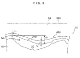
- a multi-layer coating layer is formed in production line 12 for producing a photosensitive planographic printing plate, and in the production line 12, a production process as shown in Fig. 4 is carried out, and as shown in Fig. 3, a planographic printing plate 10 in which uneven distribution of film thickness (layer thickness) between convex portion 18 and concave portion 20 in aluminum substrate 16 has been reduced is produced.
- a first coating part 24 for applying a coating solution onto an intended surface of web (continuous aluminum support) W, a first drying zone 26 to which the web W transferred from the first coating part 24 is transferred, and cooling zones 28, 30 for cooling the web transferred from the first drying zone 26 are arranged in this order.
- An undercoat application part (not shown) for applying an undercoat coating solution onto an intended surface of the web W and a drying part (not shown) for drying a coating solution film applied in the undercoat application part are also arranged in the production line 12. Accordingly, the web W delivered from the cooling zone 30 has an undercoat layer (not shown) and a photosensitive layer (sublayer) 34 formed thereon.
- a high-temperature handling part 36 for handling the web W transferred from the cooling zone 30, a second coating part 38 for applying a coating solution onto the web W delivered from the high-temperature handling part 36, a rapid drying part 42 for rapidly drying the web W delivered from the second coating part 38, and a second drying zone 46 for further drying the web W delivered from the rapid drying part 42 are arranged in this order.
- an OC layer 48 top layer is formed as a top layer on a photosensitive layer 34.
- a heat roll 50 abutted onto a side of web W on which the coating solution is not applied, and a parallel stream drying part 54 where the coating solution film applied in the second coating part 38 is dried with dry air blown parallel to the web W after contacting with the heat roll 50 (see Fig. 2) are arranged.
- the positions of the heat roll 50 and parallel stream drying part 54 are determined by taking into account the running speed of Web W, such that after the web W is coated with the coating solution in the second coating part 38, the web W can be transferred within 2 seconds to the parallel stream drying part 54.
- each air feed opening 58 is arranged in the middle of its adjacent exhaust openings. Accordingly, the surface of the coating solution film 62 formed by coating (see Fig. 3) is supplied with fresh air (outside air) wherein the partial pressure ratio of the solvent component contained in the coating solution film 62 is always low.
- a stream-regulating plate 60 for regulating the supplied air (outside air) in a direction parallel to the web W is arranged. Accordingly, the thickness of the coating solution film 62 is prevented from changing due to the drying air stream when an OC layer 48 is formed.
- the coating solution is heated at a temperature which is as high as the web temperature so that a coating solution is applied at a high speed at high temperature.
- a solvent to be easily evaporated is used as the solvent in the coating solution applied in the second coating part 38.
- the upper surface 62 U of the coating solution film 62 formed on the photosensitive layer 34 as a sublayer is virtually a horizontal plane right after application in the second coating part 38.
- the thickness t1 of the coating solution film 62 is 5 ⁇ m in the convex 18, and the thickness t2 is 8 ⁇ m in the concave 20, and the average thickness is 6 ⁇ m.
- the solvent is evaporated from the surface of the coating solution film 62, and the upper surface 48U of the OC layer 48 as the top layer forms into a shape almost contour along the upper surface 34U of the photosensitive layer 34 as the sublayer. Accordingly, the uneven thickness distribution of the top layer (OC layer) 48 between the convex 18 and concave 20 can be reduced.
- fresh air air wherein the partial pressure ratio of the solvent component is low
- the coating solution film 62 is prevented from changing its thickness with dry air, and the drying speed in the parallel stream drying part 54 is high.
- the coating solution film 62 is formed in the second coating part 38 and then immediately dried in the rapid drying part 42 where the coating solution film 62 can be dried to form the OC layer (top layer) 48 before the coating solution film 62 is leveled. Accordingly, the thickness distribution of the OC layer 48 between the convex 18 and concave 20 in the aluminum substrate 16 can be reduced, and thus a photosensitive planographic plating plate 10 having uniform thickness can be produced.
- An aluminum plate having a thickness of 0.24 mm (aluminum alloy containing 0.06% by mass of Si, 0.30% by mass of Fe, 0.014% by mass of Cu, 0.001% by mass of Mn, 0.001% by mass of Mg, 0.001% by mass of Zn and 0.03% by mass of Ti, the remainder being Al and inevitable impurities) was subjected successively to the following surface treatment.
- the plate was subjected continuously to electrochemical surface roughening treatment with an alternating current of 60 Hz.
- the electrolyte used was 10 g/L of aqueous nitric acid solution (containing 5 g/L of aluminum ion and 0.007% by mass of ammonium ion) at a temperature of 80°C.
- the aluminum plate was washed with water and then subjected to etching treatment at 32°C by spraying with an alkali solution containing sodium hydroxide at a concentration of 26% by mass and aluminum ion at a concentration of 6.5% by mass, whereby the aluminum plate was dissolved in an amount of 0.20 g/m 2 .
- the aluminum plate was washed by spraying with water, then subjected to desmutting treatment by spraying with an acidic solution containing sulfuric acid at a concentration of 25% by mass (the solution also containing 0.5% by mass of aluminum ion) at a temperature of 65°C, and washed by spraying with water.
- the aluminum plate subjected to desmutting treatment and washing with water was subjected to anodizing treatment with an anodizing device by a two-stage current feeding electric field treatment method. Sulfuric acid was fed to an electric field zone. After the anodizing treatment, the aluminum plate was washed by spraying with water. The amount of the final anodized coating was 2.7 g/m 2 .
- the aluminum support obtained by anodizing treatment was subjected to alkali metal silicate treatment (silicate treatment) by dipping it in a treatment bath of 1% by mass of aqueous sodium silicate No. 3 at a temperature of 30 °C for 10 seconds. Thereafter, the aluminum support was washed by spraying with water.
- alkali metal silicate treatment silicate treatment
- the resulting aluminum support was coated with an undercoat solution having the following composition and then dried at 80°C for 15 seconds, to form a coating thereon.
- the amount of the coating after drying was 15 mg/m 2 .
- the substrate obtained in the above procedure was coated with coating solutions to form coating layers in the production line 12 shown in Fig. 1.
- a bar coater was used in both the first coating part 24 and the second coating part 38.
- a sublayer coating solution 1 was applied in the first coating part 24 such that the coating amount after drying was 0.85 g/m 2 , and then the coating solution was dried at 178°C for 35 seconds in the first drying zone 26, and immediately cooled with cool air at 17 to 20°C in cooling zones 28 and 30 until the temperature of the support fell to 50°C.
- an upper thermal sensitive coating solution 1 kept at 50°C was applied in a second coating part 38 such that the average coating amount after drying was 0.22 g/m 2 , and immediately thereafter, the back (the side other than the side where the sublayer coating solution 1 and the upper thermal sensitive coating solution 1 were applied) of the support was heated with a heat roll 50 having a surface temperature set at 70°C, followed by drying for 2 seconds in a parallel stream drying part 54 (temperature of hot air, 120°C) until the upper thermal sensitive layer lost fluidity.
- the support was further dried at 149°C for 20 seconds and cooled with cool air at 20 to 26°C to form a planographic printing plate precursor 1.
- the unevenness of the upper thermal sensitive layer was improved, and the thickness of the coating in the thinnest part of the upper thermal sensitive layer was 0.12 ⁇ m, and the thickness of the coating in the thickest part of the sensitive layer was 0.3 ⁇ m.
- compositions of the sublayer coating solution 1 and the upper thermal layer coating solution 1 are shown below.
- planographic printing plate precursor produced according to the above procedure was exposed with a beam intensity of 2 to 10 W at a drum revolution speed of 150 rpm with Trendsetter (trade name, manufactured by Creo) to draw a solid image thereon. Then, the planographic printing plate was developed for 12 seconds with PS Processor LP940H (manufactured by Fuji Photo Film Co., Ltd.) charged with a developer DT-2 (trade name, diluted at 1:8, manufactured by Fuji Photo Film Co., Ltd.) and Finisher FG-1 (trade name, diluted at 1:1, manufactured by Fuji Photo Film Co., Ltd.), with the temperature of the liquids was kept at 30 °C. The electrical conductivity of the developer was 43 mS/cm.
- planographic printing plate precursor produced according to the above procedure was exposed with a beam intensity of 9 W at a drum revolution speed of 150 rpm with the above Trendsetter to draw a test pattern thereon, and then developed.
- the planographic printing plate precursor was developed for 12 seconds with PS Processor LP940H charged with a developer DT-2R (trade name, diluted at 1:5, a carbon dioxide gas was blown to regulate the electrical conductivity at 37 mS/cm, manufactured by Fuji Photo Film Co., Ltd.) and Finisher FG-1 (trade name, diluted at 1:1, manufactured by Fuji Photo Film Co., Ltd.), with the temperature of the liquids was kept at 30 °C.
- the planographic printing plate precursor having a test pattern drawn thereon was developed with a developer prepared by adding a suitable amount of DT-2R (diluted at 1:5) to the above developer to regulate the electrical conductivity at 39 mS/cm.
- a developer prepared by adding a suitable amount of DT-2R (diluted at 1:5) to the above developer to regulate the electrical conductivity at 39 mS/cm.
- developers each prepared by increasing the amount of DT-2R (diluted at 1:5) added to the above developer so as to increase electrical conductivity thereof serially by 2 mS/cm the above-described developing operation was repeated until the wear of the coating by development of the image became considerably noticeable.
- the surface of the planographic printing plate precursor developed at each electrical conductivity was visually evaluated to confirm whether staining or coloring attributable to the residual thermal sensitive film caused by insufficient development had occurred or not.
- the electrical conductivity of the developer with which excellent development had been feasible was determined, and then the critical electrical conductivity at which the wear of the coating by development had been somehow maintained to such a degree as not to substantially influence printing durability was determined.
- the range of from the electrical conductivity at which excellent development had been feasible to the critical electrical conductivity at which the wear of the coating by development had been somehow maintained to such a degree as not to substantially influence printing durability was regarded as the development latitude. The results are shown in Table 1.
- the production line 12 shown in Fig. 1 was used, and first the sublayer coating solution 1 was applied in the first coating part 24 such that the coating amount after drying was 0.85 g/m 2 , then dried at 178°C for 35 seconds in the first drying zone 26, and immediately cooled with cool air at 17 to 20°C in cooling zones 28 and 30 until the temperature of the support fell to 35°C.
- the upper thermal sensitive coating solution 1 at a temperature of 25°C was applied in the second coating part 38 such that the average coating amount after drying was 0.22 g/m 2 , and immediately the back of the support was heated for 2 seconds in the parallel stream drying part 54 (temperature of hot air, 120°C) and further dried at 149°C for 20 seconds and cooled with cool air at 20 to 26°C to form a planographic printing plate precursor 2.
- the unevenness of the thickness of the upper thermal sensitive layer was slightly improved, but the thickness of the coating in the thinnest part of the upper thermal sensitive layer was 0.09 ⁇ m, and the thickness of the coating in the thickest part of the sensitive layer was 0.6 ⁇ m.
- planographic printing plate precursor 2 was evaluated for its sensitivity and development latitude by the same procedure as in Example 1. The results are shown in Table 1.
- the production line 12 as shown in Fig. 1 was used, and first the sublayer coating solution 1 was applied in the first coating part 24 such that the coating amount after drying was 0.85 g/m 2 , then dried at 178°C for 35 seconds in the first drying zone 26, and immediately cooled with cool air at 17 to 20°C in cooling zones 28 and 30 until the temperature of the support fell to 35°C.
- the upper thermal sensitive coating solution 1 at a temperature of 25°C was applied in the second coating part 38 such that the average coating amount after drying was 0.22 g/m 2 , and immediately the support was dried at 149°C for 20 seconds and cooled with cool air at 20 to 26°C to form a planographic printing plate precursor 3.
- the thickness of the upper thermal sensitive layer was uneven, and the thickness of the coating in the thinnest part of the upper thermal sensitive layer was 0.06 ⁇ m, and the thickness of the coating in the thickest part of the sensitive layer was 1.0 ⁇ m.
- planographic printing plate precursor 3 was evaluated for its sensitivity and development latitude by the same procedure as in Example 1. The results are shown in Table 1.
- the planographic printing plate in Example 1 was found to have excellent sensitivity and developability with the constantly active developer, as compared with the planographic printing plates in Comparative Examples 1 and 2.
Landscapes
- Physics & Mathematics (AREA)
- General Physics & Mathematics (AREA)
- Optics & Photonics (AREA)
- Thermal Sciences (AREA)
- Engineering & Computer Science (AREA)
- Manufacturing & Machinery (AREA)
- Materials For Photolithography (AREA)
- Application Of Or Painting With Fluid Materials (AREA)
- Photosensitive Polymer And Photoresist Processing (AREA)
- Printing Plates And Materials Therefor (AREA)
Abstract
Description
- The present invention relates to a photosensitive planographic printing plate and a method of producing the same, and in particular to a photosensitive planographic printing plate most suitable as a multi-layer printing plate having a plurality of coating layers formed therein and a method of producing the same.
- In a production line for a photosensitive planographic printing plate, a web (aluminum continuous support) is fed in a longitudinal direction while one uneven side of the web is coated with a photosensitive coating solution, and this solution is dried to form a coating layer (photosensitive layer as dry film). Various attempts have been made to conduct this drying efficiently.
- For example, Japanese Patent Application Laid-Open (JP-A) No. 7-89255 prescribes the ratio of the thickness of a photosensitive layer to the height of protrusions on a grained surface of a web, and after application of a coating solution onto the web, pressurized air is blown from a slit nozzle to the resulting wet coating, to permit the surface of the photosensitive layer to have a contour shape along the uneven surface of the web. Whether the photosensitive layer is a single or multiple layer is not particularly prescribed in JP-A No. 7-89255. In JP-A No. 6-317896, a planographic printing plate is heated such that the temperature of the printing surface is kept in a range of 50 to 130°C by irradiation with far infrared rays in a drying process, thereby reducing the time required for the drying process to improve production efficiency.
- In JP-A No. 6-63487, hot air is blown over a web, and then a heat roll is brought into contact with the web so as to make the contact area changeable, thereby controlling the dry state. In JP-A No. 8-318198, a heat roll is used in the latter half of a process of drying with hot air blown over a web. In this case, the temperature of the web is monitored, the lap width of the heat roll is regulated, and heating with the heat roll and blowing of hot air are simultaneously conducted.
- As a photosensitive planographic printing plate in recent years, a direct printing plate is mainly used, and the use of a multi-layer printing plate is increasing in order to differentiate functions which are required of a photosensitive planographic printing plate. For continuous mass production of the multi-layer printing plate, a coating drying zone needs to be added to a conventional coating drying line. However, when such a coating drying zone is added, there arises a problem in that compact arrangement of facilities, reduction in running cost by effectively utilizing the quantity of heat supplied, and consistent quality of a web of continuously changing size, etc. are to be especially persued. This problem has been a task in general photosensitive planographic printing plates, as well.
- When the thickness of a coating layer (coating) is uneven in a multi-layer-type CTP plate, particularly in a thin layer of 1.0 g/m2 or less, the sensitivity of the printing plate becomes uneven. Particularly, when there is a difference in film thickness between convex and concave portions of the grained surface of each layer, a noticeable difference in sensitivity occurs, which greatly influences the performance of the printing plate.
- For example, when two layers of
underlayer 84 andtop layer 88 are formed onaluminum substrate 86 as shown in Fig. 5, the thickness d1 of thetop layer 88 intop layer portion 88S overconvex portion 92 of thealuminum substrate 86 is about 0.14 µm, while the thickness d2 of thetop layer 88 intop layer portion 88T overconcave portion 90 is about 1.0 µm. Accordingly, the excessively thintop layer portion 88S is poor in scratch resistance, while the excessively thicktop layer portion 88T results in a dotted residual coating film because of failure to remove the coating by development treatment, thus hindering improvement in product yield. In the multi-layer-type CTP plate, therefore, there is also a problem in that, in order to improve the quality thereof, thetop layer 88 must be provided with uniform thickness so that the functions of thetop layer 88, which have been differentiated, are each successfully utilized. - This has serious implications for the multi-layer-type CTP plate mainly used in recent years. That is, an immediate solution is required for the above-described problem of the top layer in the multi-layer coating layer.
- In a system of drying with air blown from an air slit nozzle as described in JP-A No. 7-89255, the speed of blown air is high. Accordingly, when this system is used in the first half of a drying process wherein a photosensitive solution film is thick, the state of the coating surface deteriorates. On the other hand, if the speed of blown air is decreased for securing the state of the coating surface, the effect of rapid drying is reduced. Thus, this system is unsuitable for drying the photosensitive solution film.
- When the air slit nozzle is used in a production line wherein the size of a web (size of an aluminum substrate) is continuously changed, the quality thereof is significantly influenced by a slight difference in drying site. Further, a difference in drying speed occurs in the width direction. In short, application of the drying system using an air slit nozzle to a method of producing a planographic printing plate wherein drying starts from the edge of a web has not been put to practical use due to the difficulty in controllability.
- It is difficult to solve the above problem even by drying methods described in other patent references.
- In consideration of the above circumstances, an object of the present invention is to provide a high-quality photosensitive planographic printing plate and a method of producing the same, wherein a coating solution film can be efficiently dried to achieve compact facilities and improved productivity, and the issue of controllability of the continuous mass production line in the prior art can be improved to achieve consistent quality and uniform thickness of a coating layer.
- A first aspect of the invention is to provide a photosensitive planographic printing plate produced by continuously running a web having a roughened surface and simultaneously forming a coating layer on the surface, wherein the coating layer contains a thinnest layer portion and a thickest layer portion, and the thinnest layer portion has a thickness of 50% or more of the average thickness of the coating layer, and the thickest layer portion has a thickness of 150% or less of the average thickness of the coating layer.
- Since the microscopic thickness distribution of the coating layer can thereby be reduced, a microscopic difference in quality (mainly difference in sensitivity) in the printing plate can be reduced to achieve consistent quality, and a problem of insufficient scratch resistance and dotted residual film occurring in the prior art can be solved. The web is generally made of aluminum. In the present specification, the coating solution film refers to a coating whose drying has not been finished, and the coating layer refers to a coating whose drying has been finished.
- In a multi-layer photosensitive planographic printing plate which is layered by successive coating, an aluminum substrate (aluminum support) subjected to graining treatment (brush grain, electrolytic grain) and anodizing treatment has unevenness at a surface thereof in a range of 1 to 5 µm in wave height at a wavelength of 1 to 30 µm.
- Recently, a printing plate generally has a very thin undercoat layer of 0.1 g/m2 or less formed on an aluminum substrate, which undercoat layer cannot be detected as a coating thickness. When a photosensitive solution is applied onto this undercoat layer to form a photosensitive layer as a sublayer having a thickness in a range of 0.2 to 1.0 g/m2, grained unevenness becomes significant relative to the thickness of the coating, and thus the coating is extremely thin in a grained convex portion, while the coating is extremely thick in a grained concave portion. As a result, a microscopic difference in performance occurs, which is attributable to the coating thickness distribution in the printing plate, and at the same time unevenness with reduced undulation resembling a pattern of grained unevenness remains on the surface of the sublayer.
- When an intermediate layer or top layer with a thickness in a range of 0.2 to 1.0 g/m2 having functions such as photosensitivity, thermal sensitivity, oxygen barrier properties and oxygen permeation controllability is formed on the sublayer, the layer formed in a convex portion of the surface of the sublayer is thin while the layer formed in a concave portion of the surface of the sublayer is thick, as is the case with the sublayer formed on the support. As a result, a microscopic difference in performance attributable to the coating thickness distribution in the top layer also occurs in the printing plate.
- When one layer in the multi-layer photosensitive planographic printing plate satisfies the first aspect, the microscopic variation in thickness distribution in that layer is reduced, thus contributing to improvement in quality of the photosensitive planographic printing plate. In this case, when the coating layer is an uppermost layer or intermediate layer, the obtained effect is significant.
- In the multi-layer photosensitive planographic printing plate, when a photosensitive sublayer having an average thickness of 0.2 to 1.0 g/m2 is applied onto a grained support having an undercoat layer of 0.1 g/m2 or less undetectable as coating thickness, and then subjected to usual drying with hot air, unevenness or irregularities with reduced undulation resembling a pattern of grained irregularities are generated on the surface of the photosensitive sublayer. A top layer is then generally formed such that, given the difference h in height between the top and the bottom of the irregularities thus generated at the surface of a sublayer, and the average thickness t of the top layer applied thereon, h and t satisfy the relationship: t/h ≤ 0.7.
- In a second aspect of the invention, there is provided a method of producing a photosensitive planographic printing plate by continuously running a web having a roughened surface and simultaneously applying a coating solution onto the surface and then drying the applied coating solution film to form a coating layer, which method comprising blowing dry air roughly parallel to the coating solution film in a drying chamber after application of the coating solution.
- The dry air is blown at a speed such that the coating solution film is prevented from being dried with the thickness distribution thereof being made uneven by the dry air.
- According to this aspect, the direction of dry air blown is roughly parallel to the coating solution film in the method of producing a photosensitive planographic printing plate, as described above. The thickness distribution of the coating solution film can thereby be prevented from becoming uneven by the force of dry air. Further, when the coating solution is applied to form multiple layers on a continuously running web, the drying facilities can be made compact.
- To achieve uniform thickness of the coating layer (particularly the top layer), the coating solution is preferably dried as rapidly as possible while the leveling of a coating solution film comprising the coating solution applied onto a web is suppressed. This can be effectively accomplished by constantly blowing air (for example fresh air) wherein the partial pressure ratio of solvent contained in the coating solution film is low, onto the coating solution film, so as not to affect the surface of the coating solution film, thus promoting evaporation of the solvent by renewal of the surface.
- In a third aspect of the invention, the method of producing a photosensitive planographic printing plate according to the second aspect further comprises alternately arranging a plurality of feed openings for feeding the dry air and a plurality of exhaust openings for exhausting the dry air in the dry chamber.
- The surface of the coating solution film is constantly supplied with fresh air wherein the partial pressure ratio of solvent contained in the coating solution film is low, and thus the speed of drying the coating solution film can be significantly increased.
- In the process of continuously producing the photosensitive planographic printing plate, generally, the size of an aluminum substrate (web) is also continuously changed. In order to suppress a change in dry state accompanying a change in thickness and width, it is preferable that the temperature of the web and the temperature of the coating solution at the time of coating are maintained as high as possible as long as these temperatures do not cause any trouble in production, and that the drying process is conducted immediately after coating. As a result, the effects of differences in web size and in drying speed in the width direction can be eliminated as much as possible.
- In a fourth aspect of the invention, the method of producing a photosensitive planographic printing plate according to the second aspect further comprises blowing the dry air at a temperature of 50°C or more within 2 seconds after applying the coating solution.
- This process is added to the method because the temperature of dry air is preferably 50°C or more in terms of promoting evaporation of the solvent contained in the coating solution, and it is preferable that the coating solution film is exposed to dry air within 2 seconds after applying the coating solution in order to dry the coating solution film rapidly.
- According to the present aspect, a difference in quality can be significantly reduced even if the web size is continuously changed.
- In a fifth aspect of the invention, the method of producing a photosensitive planographic printing plate according to the second aspect further comprises regulating the temperature of the web by bringing a heat roll into contact with the web before carrying the web to the drying chamber. The temperature of the web can thereby be prevented from dropping due to the latent heat of the solvent to be evaporated.
- In this case, the temperature of the heat roll is regulated such that there occurs no extreme fluidization within the coating solution film. From the viewpoint of rapid drying, the heat roll is abutted onto the aluminum substrate (web) preferably within 2 seconds after applying the coating solution.
- The temperature of the aluminum substrate is desirably not higher than the boiling point of a solvent component contained in an amount of not less than 10% by weight in the coating solution. When the temperature of the aluminum substrate is higher than the boiling point, a satisfactory coating layer may not be obtained due to boiling of the solvent. From a practical viewpoint, it is preferable that a solvent having a boiling point of 100°C or less is added in an amount of 50% or more as the solvent component in the coating solution.
- Since the coating solution is applied to the photosensitive layer-side surface of the web, the roller is brought into contact with the reverse side (back side) of the web. In a carrying position where the roller is not arranged, the web may be heated with hot air or radiation.
- In a sixth aspect of the invention, the method of producing a photosensitive planographic printing plate according to the fifth aspect further comprises regulating the temperature of the web after finishing drying of one coating solution film until start of application of a next coating solution, at a temperature within ±10°C relative to the temperature after finishing drying.
- The web heated in the previous process can thereby be coated with maintaining a high temperature at which coating is not disturbed, and thus the quantity of heat supplied can be effectively utilized in coating, to achieve a reduction in running cost. In this case too, the temperature of the aluminum substrate is desirably not higher than the boiling point of the solvent component contained in an amount of not less than 10% by weight in the coating solution.
- By heating in advance the coating solution to reduce the difference in temperature between the coating solution and the web, a significant effect can be achieved. For example, the coating solution is heated to a temperature within ±10°C relative to the temperature of the web. In particular, when a stable coating layer is to be formed on a web of continuously changing size, the temperature of the web which is being transferred to a coating zone where it is coated with the coating solution is regulated preferably at such predetermined temperature as described above regardless of the size of the web. In this case, it is more preferable that the coating solution is dried immediately after application.
- The solvent used in the coating solution is preferably a low-boiling solvent. The temperature of the web or the coating solution is regulated often in a range of 40 to 90°C.
- In a seventh aspect of the invention, the method of producing a photosensitive planographic printing plate according to the second aspect further comprises carrying the coating solution film such that the coating solution film is inclined toward a horizontal plane than a vertical plane, with the coating solution film facing downward, until the coating solution film is dried.
- The influence of gravity on leveling is greater when the coating solution film is positioned as the upper side of the web. Therefore, according to the present aspect, the influence of gravity on leveling of the coating solution film can be minimized.
- In the present aspect, it is also important that the leveling of the coating solution film is lowered by reducing the surface tension of the coating solution film itself. Specifically, the surface tension of the coating solution is reduced preferably to not higher than 35 dyne/cm or lower, and in order to satisfy this condition, a surfactant may be added to the coating solution. From a practical viewpoint, it is also preferable that the thickness of the coating solution film just after application is in a range of 5 to 25 cc/m2.
- The present invention is most suitable for producing a CTP printing plate, and the effect of the present invention is most significant when the invention is applied, not to the production of the lowermost layer, but to a second or upper layer of the CTP printing plate.
- By virtue of the aspects described above, a change in the coating thickness distribution in the printing plate can be suppressed according to the invention. Accordingly, a highly sensitive photosensitive planographic printing plate having uniform performance in the printing plate can be produced.
-
- Fig. 1 is schematic side view showing a production line for producing a photosensitive planographic printing plate in one embodiment of the present invention.
- Fig. 2 is a schematic diagram showing a principle of drying in a parallel stream drying part arranged in a production line used in one embodiment of the invention.
- Fig. 3 is an enlarged sectional view of a side of a photosensitive planographic printing plate produced in one embodiment of the invention.
- Fig. 4 is a flow chart showing a production process in one embodiment of the invention.
- Fig. 5 is an enlarged sectional view showing a problem of a conventional photosensitive planographic printing plate.
-
- Hereinafter, the present invention will be described by reference to embodiments thereof. In one embodiment of the invention, as shown in Fig. 1, a multi-layer coating layer is formed in
production line 12 for producing a photosensitive planographic printing plate, and in theproduction line 12, a production process as shown in Fig. 4 is carried out, and as shown in Fig. 3, aplanographic printing plate 10 in which uneven distribution of film thickness (layer thickness) betweenconvex portion 18 andconcave portion 20 inaluminum substrate 16 has been reduced is produced. - In
production 12, afirst coating part 24 for applying a coating solution onto an intended surface of web (continuous aluminum support) W, afirst drying zone 26 to which the web W transferred from thefirst coating part 24 is transferred, andcooling zones first drying zone 26 are arranged in this order. An undercoat application part (not shown) for applying an undercoat coating solution onto an intended surface of the web W and a drying part (not shown) for drying a coating solution film applied in the undercoat application part are also arranged in theproduction line 12. Accordingly, the web W delivered from the coolingzone 30 has an undercoat layer (not shown) and a photosensitive layer (sublayer) 34 formed thereon. - In
production line 12, a high-temperature handling part 36 for handling the web W transferred from the coolingzone 30, asecond coating part 38 for applying a coating solution onto the web W delivered from the high-temperature handling part 36, arapid drying part 42 for rapidly drying the web W delivered from thesecond coating part 38, and asecond drying zone 46 for further drying the web W delivered from the rapid dryingpart 42 are arranged in this order. In the web W transferred from thesecond drying zone 46, an OC layer 48 (top layer) is formed as a top layer on aphotosensitive layer 34. - In the rapid drying
part 42, aheat roll 50 abutted onto a side of web W on which the coating solution is not applied, and a parallelstream drying part 54 where the coating solution film applied in thesecond coating part 38 is dried with dry air blown parallel to the web W after contacting with the heat roll 50 (see Fig. 2) are arranged. The positions of theheat roll 50 and parallelstream drying part 54 are determined by taking into account the running speed of Web W, such that after the web W is coated with the coating solution in thesecond coating part 38, the web W can be transferred within 2 seconds to the parallelstream drying part 54. - In the parallel
stream drying part 54, as shown in Fig. 2,air exhaust openings 56 andair feed openings 58 arranged at predetermined intervals to exhaust air in multiple stages are provided, and eachair feed opening 58 is arranged in the middle of its adjacent exhaust openings. Accordingly, the surface of thecoating solution film 62 formed by coating (see Fig. 3) is supplied with fresh air (outside air) wherein the partial pressure ratio of the solvent component contained in thecoating solution film 62 is always low. In theair feed opening 58, a stream-regulatingplate 60 for regulating the supplied air (outside air) in a direction parallel to the web W is arranged. Accordingly, the thickness of thecoating solution film 62 is prevented from changing due to the drying air stream when an OC layer 48 is formed. - In the
second coating part 38, the coating solution is heated at a temperature which is as high as the web temperature so that a coating solution is applied at a high speed at high temperature. As the solvent in the coating solution applied in thesecond coating part 38, a solvent to be easily evaporated is used. - As shown in the dotted line in Fig. 3, the
upper surface 62 U of thecoating solution film 62 formed on thephotosensitive layer 34 as a sublayer is virtually a horizontal plane right after application in thesecond coating part 38. For example, when the difference h in height between the convex 18 and concave 20 in thealuminum substrate 16 is 3 µm, the thickness t1 of thecoating solution film 62 is 5 µm in the convex 18, and the thickness t2 is 8 µm in the concave 20, and the average thickness is 6 µm. - When the web W is dried in this state in the rapid drying
part 42, the solvent is evaporated from the surface of thecoating solution film 62, and theupper surface 48U of the OC layer 48 as the top layer forms into a shape almost contour along theupper surface 34U of thephotosensitive layer 34 as the sublayer. Accordingly, the uneven thickness distribution of the top layer (OC layer) 48 between the convex 18 and concave 20 can be reduced. - In this example described above, fresh air (air wherein the partial pressure ratio of the solvent component is low) runs parallel to the web W in the parallel
stream drying part 54, and thus thecoating solution film 62 is prevented from changing its thickness with dry air, and the drying speed in the parallelstream drying part 54 is high. Thecoating solution film 62 is formed in thesecond coating part 38 and then immediately dried in the rapid dryingpart 42 where thecoating solution film 62 can be dried to form the OC layer (top layer) 48 before thecoating solution film 62 is leveled. Accordingly, the thickness distribution of the OC layer 48 between the convex 18 and concave 20 in thealuminum substrate 16 can be reduced, and thus a photosensitiveplanographic plating plate 10 having uniform thickness can be produced. - An aluminum plate having a thickness of 0.24 mm (aluminum alloy containing 0.06% by mass of Si, 0.30% by mass of Fe, 0.014% by mass of Cu, 0.001% by mass of Mn, 0.001% by mass of Mg, 0.001% by mass of Zn and 0.03% by mass of Ti, the remainder being Al and inevitable impurities) was subjected successively to the following surface treatment.
- The plate was subjected continuously to electrochemical surface roughening treatment with an alternating current of 60 Hz. The electrolyte used was 10 g/L of aqueous nitric acid solution (containing 5 g/L of aluminum ion and 0.007% by mass of ammonium ion) at a temperature of 80°C.
- After the electrochemical surface roughening treatment, the aluminum plate was washed with water and then subjected to etching treatment at 32°C by spraying with an alkali solution containing sodium hydroxide at a concentration of 26% by mass and aluminum ion at a concentration of 6.5% by mass, whereby the aluminum plate was dissolved in an amount of 0.20 g/m2.
- After the etching treatment, the aluminum plate was washed by spraying with water, then subjected to desmutting treatment by spraying with an acidic solution containing sulfuric acid at a concentration of 25% by mass (the solution also containing 0.5% by mass of aluminum ion) at a temperature of 65°C, and washed by spraying with water.
- The aluminum plate subjected to desmutting treatment and washing with water was subjected to anodizing treatment with an anodizing device by a two-stage current feeding electric field treatment method. Sulfuric acid was fed to an electric field zone. After the anodizing treatment, the aluminum plate was washed by spraying with water. The amount of the final anodized coating was 2.7 g/m2.
- The aluminum support obtained by anodizing treatment was subjected to alkali metal silicate treatment (silicate treatment) by dipping it in a treatment bath of 1% by mass of aqueous sodium silicate No. 3 at a temperature of 30 °C for 10 seconds. Thereafter, the aluminum support was washed by spraying with water.
- After the alkali metal silicate treatment, the resulting aluminum support was coated with an undercoat solution having the following composition and then dried at 80°C for 15 seconds, to form a coating thereon. The amount of the coating after drying was 15 mg/m2.
-
- The following compound (formula 1) 0.3 g
- Methanol 100 g
- Water 1 g
- Weight average molecular weight 28,000
- The substrate obtained in the above procedure was coated with coating solutions to form coating layers in the
production line 12 shown in Fig. 1. In theproduction line 12, a bar coater was used in both thefirst coating part 24 and thesecond coating part 38. - First, a sublayer coating solution 1 was applied in the
first coating part 24 such that the coating amount after drying was 0.85 g/m2, and then the coating solution was dried at 178°C for 35 seconds in thefirst drying zone 26, and immediately cooled with cool air at 17 to 20°C in coolingzones - Next, while the temperature of the support was kept at 50°C in a high-
temperature handling part 36, an upper thermal sensitive coating solution 1 kept at 50°C was applied in asecond coating part 38 such that the average coating amount after drying was 0.22 g/m2, and immediately thereafter, the back (the side other than the side where the sublayer coating solution 1 and the upper thermal sensitive coating solution 1 were applied) of the support was heated with aheat roll 50 having a surface temperature set at 70°C, followed by drying for 2 seconds in a parallel stream drying part 54 (temperature of hot air, 120°C) until the upper thermal sensitive layer lost fluidity. The support was further dried at 149°C for 20 seconds and cooled with cool air at 20 to 26°C to form a planographic printing plate precursor 1. - In the planographic printing plate precursor 1, the unevenness of the upper thermal sensitive layer was improved, and the thickness of the coating in the thinnest part of the upper thermal sensitive layer was 0.12 µm, and the thickness of the coating in the thickest part of the sensitive layer was 0.3 µm.
- The compositions of the sublayer coating solution 1 and the upper thermal layer coating solution 1 are shown below.
-
- N-(4-aminosulfonylphenyl)methacrylamide/ 2.133 g acrylonitrile/methyl methacrylate copolymer (copolymerization molar ratio = 36/34/30, weight average molecular weight 50,000, acid value 2.65)
- Cyanine dye A (shown in formula 2 below) 0.134 g
- 4,4'-Bishydroxyphenyl sulfone 0.126 g
- Tertrahydrophthalic anhydride 0.190 g
- p-Toluenesulfonic acid 0.008 g
- 3-Methoxy-4-diazodiphenylamine hexafluorophosphate 0.032 g
- Ethyl Violet whose counterion was replaced by 0.0781 g 6-hydroxynaphthalenesulfonic acid
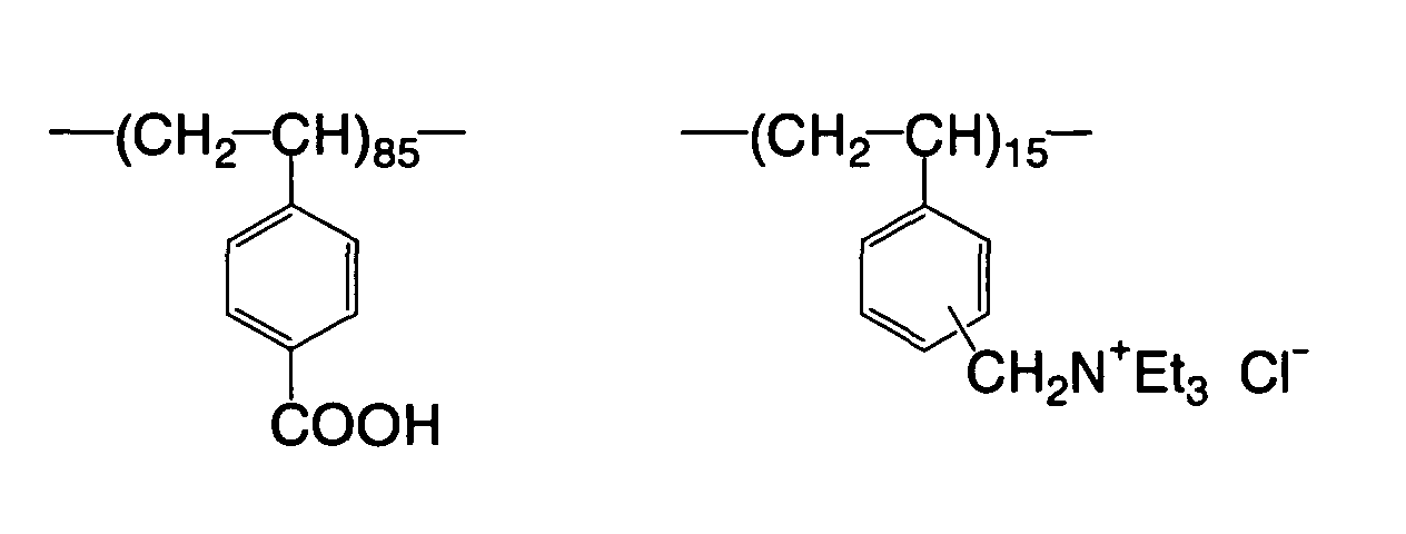
- Polymer 1 (shown in formula 3 below) 0.035 g
- Methyl ethyl ketone 25.41 g
- 1-Methoxy-2-propanol 12.97 g
- γ-Butyrolactone 13.18 g
-
- m, p-Cresol novolak 0.3479 g
(m/p ratio 6/4,
weight average molecular weight 4500,
containing 0.8% by mass of unreacted cresol) - Cyanine dye A (shown in formula 2 above) 0.0192 g
- Ethyl methacrylate/isobutyl methacrylate/ 0.1403 g
acrylic acid copolymer
(copolymerization ratio = 37/37/26 wt%) 30% MEK solution - Polymer 1 (shown in formula 3 above) 0.015 g
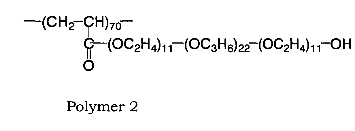
- Polymer 2 (shown in formula 4 below) 0.00328 g
- Methyl ethyl ketone 10.39 g
- 1-Methoxy-2-propanol 20.78 g
- The planographic printing plate precursor produced according to the above procedure was exposed with a beam intensity of 2 to 10 W at a drum revolution speed of 150 rpm with Trendsetter (trade name, manufactured by Creo) to draw a solid image thereon. Then, the planographic printing plate was developed for 12 seconds with PS Processor LP940H (manufactured by Fuji Photo Film Co., Ltd.) charged with a developer DT-2 (trade name, diluted at 1:8, manufactured by Fuji Photo Film Co., Ltd.) and Finisher FG-1 (trade name, diluted at 1:1, manufactured by Fuji Photo Film Co., Ltd.), with the temperature of the liquids was kept at 30 °C. The electrical conductivity of the developer was 43 mS/cm.
- After development, the plate was observed with a 25-power magnifying glass, and evaluated on whether a residual coating at a level not substantially causing staining had occurred or not. From the intensity of exposure beam on a portion where no residual coating had been observed, the actual exposure energy was calculated to determine the sensitivity. The evaluation results are shown in Table 1. A planographic printing plate with less exposure energy has higher sensitivity.
- The planographic printing plate precursor produced according to the above procedure was exposed with a beam intensity of 9 W at a drum revolution speed of 150 rpm with the above Trendsetter to draw a test pattern thereon, and then developed. The planographic printing plate precursor was developed for 12 seconds with PS Processor LP940H charged with a developer DT-2R (trade name, diluted at 1:5, a carbon dioxide gas was blown to regulate the electrical conductivity at 37 mS/cm, manufactured by Fuji Photo Film Co., Ltd.) and Finisher FG-1 (trade name, diluted at 1:1, manufactured by Fuji Photo Film Co., Ltd.), with the temperature of the liquids was kept at 30 °C. Then, the planographic printing plate precursor having a test pattern drawn thereon was developed with a developer prepared by adding a suitable amount of DT-2R (diluted at 1:5) to the above developer to regulate the electrical conductivity at 39 mS/cm. By using developers each prepared by increasing the amount of DT-2R (diluted at 1:5) added to the above developer so as to increase electrical conductivity thereof serially by 2 mS/cm, the above-described developing operation was repeated until the wear of the coating by development of the image became considerably noticeable.
- The surface of the planographic printing plate precursor developed at each electrical conductivity was visually evaluated to confirm whether staining or coloring attributable to the residual thermal sensitive film caused by insufficient development had occurred or not. The electrical conductivity of the developer with which excellent development had been feasible was determined, and then the critical electrical conductivity at which the wear of the coating by development had been somehow maintained to such a degree as not to substantially influence printing durability was determined. The range of from the electrical conductivity at which excellent development had been feasible to the critical electrical conductivity at which the wear of the coating by development had been somehow maintained to such a degree as not to substantially influence printing durability was regarded as the development latitude. The results are shown in Table 1.
Minimum thickness of the top layer (µm) Maximum thickness of the top layer (µm) Sensitivity (mJ/cm2) Development latitude (mS/cm) Example 1 Planographic Printing plate precursor 1 0.15 0.30 55 39 to 49 Comparative Example 1 Planographic printing plate precursor 2 0.09 0.60 63 41 to 49 Comparative Example 2 Planographic Printing plate precursor 3 0.06 1.00 65 41 to 49 - The
production line 12 shown in Fig. 1 was used, and first the sublayer coating solution 1 was applied in thefirst coating part 24 such that the coating amount after drying was 0.85 g/m2, then dried at 178°C for 35 seconds in thefirst drying zone 26, and immediately cooled with cool air at 17 to 20°C in coolingzones - Next, the upper thermal sensitive coating solution 1 at a temperature of 25°C was applied in the
second coating part 38 such that the average coating amount after drying was 0.22 g/m2, and immediately the back of the support was heated for 2 seconds in the parallel stream drying part 54 (temperature of hot air, 120°C) and further dried at 149°C for 20 seconds and cooled with cool air at 20 to 26°C to form a planographic printing plate precursor 2. - In the planographic printing plate precursor 2, the unevenness of the thickness of the upper thermal sensitive layer was slightly improved, but the thickness of the coating in the thinnest part of the upper thermal sensitive layer was 0.09 µm, and the thickness of the coating in the thickest part of the sensitive layer was 0.6 µm.
- The planographic printing plate precursor 2 was evaluated for its sensitivity and development latitude by the same procedure as in Example 1. The results are shown in Table 1.
- The
production line 12 as shown in Fig. 1 was used, and first the sublayer coating solution 1 was applied in thefirst coating part 24 such that the coating amount after drying was 0.85 g/m2, then dried at 178°C for 35 seconds in thefirst drying zone 26, and immediately cooled with cool air at 17 to 20°C in coolingzones - Next, the upper thermal sensitive coating solution 1 at a temperature of 25°C was applied in the
second coating part 38 such that the average coating amount after drying was 0.22 g/m2, and immediately the support was dried at 149°C for 20 seconds and cooled with cool air at 20 to 26°C to form a planographic printing plate precursor 3. - In the planographic printing plate precursor 3, the thickness of the upper thermal sensitive layer was uneven, and the thickness of the coating in the thinnest part of the upper thermal sensitive layer was 0.06 µm, and the thickness of the coating in the thickest part of the sensitive layer was 1.0 µm.
- The planographic printing plate precursor 3 was evaluated for its sensitivity and development latitude by the same procedure as in Example 1. The results are shown in Table 1.
- As is evident from Table 1, by making the minimum thickness of the upper thermal sensitive layer greater than 50% (0.11 µm) of the average thickness of the thermal sensitive layer and the maximum thickness of the thermal sensitive layer less than 150% (0.33 µm) of the average thickness of the thermal sensitive layer, occurrence of dotted residual film can be suppressed. In conclusion, the planographic printing plate in Example 1 was found to have excellent sensitivity and developability with the constantly active developer, as compared with the planographic printing plates in Comparative Examples 1 and 2.
- The invention has been described above by reference to the embodiments thereof. However, these embodiments are described for mere illustrative purposes, and the invention can be modified within the scope of the invention. Needless to say, the scope of the invention is not limited to the above embodiments.


Claims (20)
- A photosensitive planographic printing plate produced by continuously running a web having a roughened surface and simultaneously forming a coating layer on the surface, the coating layer comprising:wherein the thinnest layer portion has a thickness of 50% or more of the average thickness of the coating layer, and the thickest layer portion has a thickness of 150% or less of the average thickness of the coating layer.a thinnest layer portion; anda thickest layer portion,
- A photosensitive planographic printing plate according to claim 1, which is a multi-layer photosensitive planographic printing plate wherein the coating layer is an uppermost layer or an intermediate layer.
- A photosensitive planographic printing plate according to claim 1, wherein the average thickness of the coating layer is in a range of 0.2 µm to 1.0 µm.
- A photosensitive planographic printing plate according to claim 3, wherein the difference h in height between a concave portion and a convex portion of the coating surface of the web, and the average thickness t of the coating layer, satisfy the relationship: t/h ≤ 0.7.
- A photosensitive planographic printing plate produced by continuously running a web having a roughened surface and simultaneously forming one or more coating layers sequentially on the surface,
each of the coating layers comprising:wherein, in at least one of an uppermost layer and an intermediate layer just under the uppermost layer of the coating layers, the thinnest layer portion has a thickness of 50% or more of the average layer thickness, and the thickest layer portion has a thickness of 150% or less of the average layer thickness, anda thinnest layer portion;a thickest layer portion; andan average layer thickness,
the difference h in height between a concave portion and a convex portion of the coating surface of the web and the average thickness t of at least one of the uppermost layer and the intermediate layer, satisfy the relationship: t/h ≤ 0.7. - A photosensitive planographic printing plate according to claim 5, wherein the average thickness of the coating layer is in a range of 0.2 µm to 1.0 µm.
- A photosensitive planographic printing plate according to claim 5, wherein the coating layer is formed by blowing dry air onto a coating solution film formed by application of a coating solution, such that the dry air is blown roughly parallel to the coating solution film.
- A method of producing a photosensitive planographic printing plate by continuously running a web having a roughened surface and simultaneously applying a coating solution onto the surface and then drying a film of the applied coating solution to form a coating layer, the method comprising:blowing dry air roughly parallel to the film of the coating solution in a drying chamber after application of the coating solution.
- A method of producing a photosensitive planographic printing plate according to claim 8, further comprising alternately arranging a plurality of feed openings for feeding the dry air and a plurality of exhaust openings for exhausting the dry air in the dry chamber.
- A method of producing a photosensitive planographic printing plate according to claim 8, further comprising blowing the dry air at a temperature of 50°C or more within 2 seconds after application of the coating solution.
- A method of producing a photosensitive planographic printing plate according to claim 8, further comprising regulating the temperature of the web by bringing a heat roll into contact with the web before transferring the web to the drying chamber.
- A method of producing a photosensitive planographic printing plate according to claim 11, further comprising regulating the temperature of the web after finishing drying of one coating solution film until start of application of a next coating solution, at a temperature within ±10°C relative to the temperature after finishing drying.
- A method of producing a photosensitive planographic printing plate according to claim 8, further comprising carrying the coating solution film such that the coating solution film is inclined toward a horizontal plane than a vertical plane, with the coating solution film facing downward, until the coating solution film is dried.
- A method of producing a photosensitive planographic printing plate by continuously running a web having a roughened surface and simultaneously applying a coating solution onto the surface and then drying a film of the applied coating solution to form a coating layer, the method comprising:carrying the coating solution film such that the coating solution film is inclined toward a horizontal plane than a vertical plane, with the coating solution film facing downward, until the coating solution film is dried; andblowing dry air onto the film of the coating solution in a drying chamber during the carrying process such that the dry air is blown roughly parallel to the coating solution film.
- A method of producing a photosensitive planographic printing plate according to claim 14, further comprising constantly blowing, onto the coating solution film, air as the dry air wherein the partial pressure ratio of solvent contained in the coating solution film is low.
- A method of producing a photosensitive planographic printing plate according to claim 15, further comprising feeding and exhausting the dry air via a plurality of feed openings for feeding the dry air and a plurality of exhaust openings for exhausting the dry air which are arranged alternately in the dry chamber.
- A method of producing a photosensitive planographic printing plate according to claim 14, further comprising blowing the dry air at a temperature of 50°C or more within 2 seconds after applying the coating solution.
- A method of producing a photosensitive planographic printing plate according to claim 14, further comprising regulating the temperature of the web by bringing a heat roll into contact with the web before transferring the web to the drying chamber.
- A method of producing a photosensitive planographic printing plate according to claim 14, further comprising regulating the temperature of the web after finishing drying of one coating solution film until start of application of a next coating solution, at a temperature within ±10°C relative to the temperature after finishing drying.
- A method of producing a photosensitive planographic printing plate according to claim 14, further comprising regulating the surface tension of the coating solution at 35 dyne/cm or less.
Applications Claiming Priority (2)
| Application Number | Priority Date | Filing Date | Title |
|---|---|---|---|
| JP2003324462 | 2003-09-17 | ||
| JP2003324462 | 2003-09-17 |
Publications (3)
| Publication Number | Publication Date |
|---|---|
| EP1516746A2 true EP1516746A2 (en) | 2005-03-23 |
| EP1516746A3 EP1516746A3 (en) | 2007-07-11 |
| EP1516746B1 EP1516746B1 (en) | 2009-12-02 |
Family
ID=34191301
Family Applications (1)
| Application Number | Title | Priority Date | Filing Date |
|---|---|---|---|
| EP04022192A Expired - Lifetime EP1516746B1 (en) | 2003-09-17 | 2004-09-17 | Photosensitive planographic printing plate and method of producing the same |
Country Status (5)
| Country | Link |
|---|---|
| US (2) | US7270058B2 (en) |
| EP (1) | EP1516746B1 (en) |
| CN (1) | CN100573318C (en) |
| AT (1) | ATE450812T1 (en) |
| DE (1) | DE602004024359D1 (en) |
Families Citing this family (1)
| Publication number | Priority date | Publication date | Assignee | Title |
|---|---|---|---|---|
| JP2006297378A (en) * | 2005-03-22 | 2006-11-02 | Fuji Photo Film Co Ltd | Method for producing coated article |
Citations (13)
| Publication number | Priority date | Publication date | Assignee | Title |
|---|---|---|---|---|
| US3508924A (en) | 1965-08-17 | 1970-04-28 | Ball Corp | Lithographic plate and method of making same |
| CH668654A5 (en) | 1985-04-13 | 1989-01-13 | Kurt Etter Dr | Continuous prodn. equipment for presensitised lithographic plates - incorporates station for oxidn. or silicate treatment of strip or plate between preliminary and final rinses |
| JPH06135174A (en) | 1992-10-29 | 1994-05-17 | Mitsubishi Paper Mills Ltd | Protective rubber solution coating treater |
| JPH0789255A (en) | 1993-09-20 | 1995-04-04 | Fuji Photo Film Co Ltd | Photosensitive lithographic plate and its manufacture |
| EP0766140A1 (en) | 1995-09-27 | 1997-04-02 | Fuji Photo Film Co., Ltd. | Positive presensitized lithographic printing plate and a process for producing the same |
| US6014929A (en) | 1998-03-09 | 2000-01-18 | Teng; Gary Ganghui | Lithographic printing plates having a thin releasable interlayer overlying a rough substrate |
| US6242156B1 (en) | 2000-06-28 | 2001-06-05 | Gary Ganghui Teng | Lithographic plate having a conformal radiation-sensitive layer on a rough substrate |
| EP1106382A1 (en) | 1999-12-07 | 2001-06-13 | Agfa-Gevaert | Heat sensitive printing plate precursors |
| EP1157854A2 (en) | 2000-05-15 | 2001-11-28 | Fuji Photo Film Co., Ltd. | Support for lithographic printing plate and presensitized plate |
| EP1172697A2 (en) | 2000-06-30 | 2002-01-16 | Fuji Photo Film Co., Ltd. | Method of manufacturing lithographic printing plate |
| WO2003008672A1 (en) | 2001-07-20 | 2003-01-30 | Alcan International Limited | Aluminium alloy sheet with roughened surface |
| EP1287986A1 (en) | 2001-04-26 | 2003-03-05 | Mitsubishi Chemical Corporation | Method and device for regenerative processing and printing |
| WO2003073164A2 (en) | 2002-02-27 | 2003-09-04 | Brewer Science, Inc. | Novel planarization method for multi-layer lithography processing |
Family Cites Families (6)
| Publication number | Priority date | Publication date | Assignee | Title |
|---|---|---|---|---|
| US3511661A (en) * | 1966-07-01 | 1970-05-12 | Eastman Kodak Co | Lithographic printing plate |
| AU2792395A (en) * | 1994-06-23 | 1996-01-19 | Hans-Jurgen Schafer | Method and device for coating printed-circuit boards, in particular for the manufacture of multi-chip-modules |
| JP2001329385A (en) * | 2000-05-19 | 2001-11-27 | Toshiba Corp | Method and apparatus for producing etched product |
| JP2002116552A (en) * | 2000-10-04 | 2002-04-19 | Mitsubishi Chemicals Corp | Photosensitive planographic printing plate and plate making method for the same |
| JP2003103210A (en) | 2001-09-28 | 2003-04-08 | Fuji Photo Film Co Ltd | Coating apparatus and coating method |
| KR20030075951A (en) * | 2002-03-22 | 2003-09-26 | 신현우 | Heating apparatus for adhesion |
-
2004
- 2004-09-16 US US10/941,841 patent/US7270058B2/en not_active Expired - Lifetime
- 2004-09-16 CN CN200410078677.3A patent/CN100573318C/en not_active Expired - Lifetime
- 2004-09-17 DE DE602004024359T patent/DE602004024359D1/en not_active Expired - Lifetime
- 2004-09-17 AT AT04022192T patent/ATE450812T1/en not_active IP Right Cessation
- 2004-09-17 EP EP04022192A patent/EP1516746B1/en not_active Expired - Lifetime
-
2007
- 2007-07-11 US US11/822,943 patent/US7654200B2/en not_active Expired - Fee Related
Patent Citations (13)
| Publication number | Priority date | Publication date | Assignee | Title |
|---|---|---|---|---|
| US3508924A (en) | 1965-08-17 | 1970-04-28 | Ball Corp | Lithographic plate and method of making same |
| CH668654A5 (en) | 1985-04-13 | 1989-01-13 | Kurt Etter Dr | Continuous prodn. equipment for presensitised lithographic plates - incorporates station for oxidn. or silicate treatment of strip or plate between preliminary and final rinses |
| JPH06135174A (en) | 1992-10-29 | 1994-05-17 | Mitsubishi Paper Mills Ltd | Protective rubber solution coating treater |
| JPH0789255A (en) | 1993-09-20 | 1995-04-04 | Fuji Photo Film Co Ltd | Photosensitive lithographic plate and its manufacture |
| EP0766140A1 (en) | 1995-09-27 | 1997-04-02 | Fuji Photo Film Co., Ltd. | Positive presensitized lithographic printing plate and a process for producing the same |
| US6014929A (en) | 1998-03-09 | 2000-01-18 | Teng; Gary Ganghui | Lithographic printing plates having a thin releasable interlayer overlying a rough substrate |
| EP1106382A1 (en) | 1999-12-07 | 2001-06-13 | Agfa-Gevaert | Heat sensitive printing plate precursors |
| EP1157854A2 (en) | 2000-05-15 | 2001-11-28 | Fuji Photo Film Co., Ltd. | Support for lithographic printing plate and presensitized plate |
| US6242156B1 (en) | 2000-06-28 | 2001-06-05 | Gary Ganghui Teng | Lithographic plate having a conformal radiation-sensitive layer on a rough substrate |
| EP1172697A2 (en) | 2000-06-30 | 2002-01-16 | Fuji Photo Film Co., Ltd. | Method of manufacturing lithographic printing plate |
| EP1287986A1 (en) | 2001-04-26 | 2003-03-05 | Mitsubishi Chemical Corporation | Method and device for regenerative processing and printing |
| WO2003008672A1 (en) | 2001-07-20 | 2003-01-30 | Alcan International Limited | Aluminium alloy sheet with roughened surface |
| WO2003073164A2 (en) | 2002-02-27 | 2003-09-04 | Brewer Science, Inc. | Novel planarization method for multi-layer lithography processing |
Also Published As
| Publication number | Publication date |
|---|---|
| US7654200B2 (en) | 2010-02-02 |
| EP1516746B1 (en) | 2009-12-02 |
| CN100573318C (en) | 2009-12-23 |
| DE602004024359D1 (en) | 2010-01-14 |
| US20070256584A1 (en) | 2007-11-08 |
| CN1598693A (en) | 2005-03-23 |
| US7270058B2 (en) | 2007-09-18 |
| US20050061178A1 (en) | 2005-03-24 |
| ATE450812T1 (en) | 2009-12-15 |
| EP1516746A3 (en) | 2007-07-11 |
Similar Documents
| Publication | Publication Date | Title |
|---|---|---|
| JP4233199B2 (en) | Planographic printing plate manufacturing method | |
| US20030165768A1 (en) | Support for lithographic printing plate and presensitized plate and method of producing lithographic printing plate | |
| JP2002357894A (en) | Original plate for planographic printing plate and processing method for the same | |
| US7654200B2 (en) | Photosensitive planographic printing plate and method of producing the same | |
| JP2001117215A (en) | Quality control method for planographic printing plate | |
| JP2005115357A (en) | Photosensitive planographic printing plate and method of manufacturing the same | |
| JP4335399B2 (en) | Quality control method for lithographic printing plates | |
| JP4085005B2 (en) | Master for lithographic printing plate | |
| JP4234990B2 (en) | Method for producing lithographic printing original plate and lithographic printing original plate | |
| JP2002293055A (en) | Method for manufacturing substrate for lithographic printing plate, substrate for lithographic printing plate, and original plate for lithographic printing plate | |
| EP1566699A2 (en) | Automatic development method of photosensitive lithographic printing plate and automatic development device thereof | |
| JP4242576B2 (en) | Planographic printing plate precursor and lithographic printing plate making method | |
| JP4732108B2 (en) | Planographic printing plate manufacturing method | |
| JP4315535B2 (en) | Quality control method for lithographic printing plates | |
| JP2004117547A (en) | Lithographic printing master plate | |
| JP2006240116A (en) | Support for lithographic printing plate and its manufacturing method | |
| US20050271381A1 (en) | Method for replenishing development replenisher in automatic developing machine for photosensitive lithographic printing plate precursor | |
| JP2001215692A (en) | Master plate for planographic printing plate and method of producing the same | |
| JP2004271974A (en) | Method for detecting fatigue degree of developer for photosensitive lithographic printing plate and method for controlling developer | |
| JP2005258090A (en) | Lithographic printing plate original form | |
| JP2004341036A (en) | Platemaking method for lithographic printing plate | |
| JP2001209184A (en) | Photosensitive planographic printing plate | |
| JP2004246035A (en) | Precursor for planographic printing plate | |
| JP2002123000A (en) | Quality control method for planographic printing plate | |
| JP2004271973A (en) | Method for detecting developer fatigue of photosensitive lithographic printing plate and method for managing developer |
Legal Events
| Date | Code | Title | Description |
|---|---|---|---|
| PUAI | Public reference made under article 153(3) epc to a published international application that has entered the european phase |
Free format text: ORIGINAL CODE: 0009012 |
|
| AK | Designated contracting states |
Kind code of ref document: A2 Designated state(s): AT BE BG CH CY CZ DE DK EE ES FI FR GB GR HU IE IT LI LU MC NL PL PT RO SE SI SK TR |
|
| AX | Request for extension of the european patent |
Extension state: AL HR LT LV MK |
|
| RIC1 | Information provided on ipc code assigned before grant |
Ipc: G03F 7/16 20060101AFI20061219BHEP Ipc: B41N 3/04 20060101ALI20061219BHEP Ipc: B41N 3/03 20060101ALI20061219BHEP |
|
| RAP1 | Party data changed (applicant data changed or rights of an application transferred) |
Owner name: FUJIFILM CORPORATION |
|
| PUAL | Search report despatched |
Free format text: ORIGINAL CODE: 0009013 |
|
| AK | Designated contracting states |
Kind code of ref document: A3 Designated state(s): AT BE BG CH CY CZ DE DK EE ES FI FR GB GR HU IE IT LI LU MC NL PL PT RO SE SI SK TR |
|
| AX | Request for extension of the european patent |
Extension state: AL HR LT LV MK |
|
| RIC1 | Information provided on ipc code assigned before grant |
Ipc: B41N 3/03 20060101ALI20070606BHEP Ipc: G03F 7/16 20060101AFI20061219BHEP Ipc: B41C 1/10 20060101ALI20070606BHEP Ipc: B41N 3/04 20060101ALI20070606BHEP |
|
| 17P | Request for examination filed |
Effective date: 20071019 |
|
| 17Q | First examination report despatched |
Effective date: 20071122 |
|
| AKX | Designation fees paid |
Designated state(s): AT BE BG CH CY CZ DE DK EE ES FI FR GB GR HU IE IT LI LU MC NL PL PT RO SE SI SK TR |
|
| GRAP | Despatch of communication of intention to grant a patent |
Free format text: ORIGINAL CODE: EPIDOSNIGR1 |
|
| GRAS | Grant fee paid |
Free format text: ORIGINAL CODE: EPIDOSNIGR3 |
|
| GRAA | (expected) grant |
Free format text: ORIGINAL CODE: 0009210 |
|
| AK | Designated contracting states |
Kind code of ref document: B1 Designated state(s): AT BE BG CH CY CZ DE DK EE ES FI FR GB GR HU IE IT LI LU MC NL PL PT RO SE SI SK TR |
|
| REG | Reference to a national code |
Ref country code: GB Ref legal event code: FG4D |
|
| REG | Reference to a national code |
Ref country code: CH Ref legal event code: EP |
|
| REG | Reference to a national code |
Ref country code: IE Ref legal event code: FG4D |
|
| REF | Corresponds to: |
Ref document number: 602004024359 Country of ref document: DE Date of ref document: 20100114 Kind code of ref document: P |
|
| REG | Reference to a national code |
Ref country code: NL Ref legal event code: VDEP Effective date: 20091202 |
|
| PG25 | Lapsed in a contracting state [announced via postgrant information from national office to epo] |
Ref country code: SE Free format text: LAPSE BECAUSE OF FAILURE TO SUBMIT A TRANSLATION OF THE DESCRIPTION OR TO PAY THE FEE WITHIN THE PRESCRIBED TIME-LIMIT Effective date: 20091202 Ref country code: FI Free format text: LAPSE BECAUSE OF FAILURE TO SUBMIT A TRANSLATION OF THE DESCRIPTION OR TO PAY THE FEE WITHIN THE PRESCRIBED TIME-LIMIT Effective date: 20091202 |
|
| PG25 | Lapsed in a contracting state [announced via postgrant information from national office to epo] |
Ref country code: PL Free format text: LAPSE BECAUSE OF FAILURE TO SUBMIT A TRANSLATION OF THE DESCRIPTION OR TO PAY THE FEE WITHIN THE PRESCRIBED TIME-LIMIT Effective date: 20091202 Ref country code: CY Free format text: LAPSE BECAUSE OF FAILURE TO SUBMIT A TRANSLATION OF THE DESCRIPTION OR TO PAY THE FEE WITHIN THE PRESCRIBED TIME-LIMIT Effective date: 20091202 Ref country code: SI Free format text: LAPSE BECAUSE OF FAILURE TO SUBMIT A TRANSLATION OF THE DESCRIPTION OR TO PAY THE FEE WITHIN THE PRESCRIBED TIME-LIMIT Effective date: 20091202 |
|
| PG25 | Lapsed in a contracting state [announced via postgrant information from national office to epo] |
Ref country code: AT Free format text: LAPSE BECAUSE OF FAILURE TO SUBMIT A TRANSLATION OF THE DESCRIPTION OR TO PAY THE FEE WITHIN THE PRESCRIBED TIME-LIMIT Effective date: 20091202 |
|
| PG25 | Lapsed in a contracting state [announced via postgrant information from national office to epo] |
Ref country code: BG Free format text: LAPSE BECAUSE OF FAILURE TO SUBMIT A TRANSLATION OF THE DESCRIPTION OR TO PAY THE FEE WITHIN THE PRESCRIBED TIME-LIMIT Effective date: 20100302 Ref country code: RO Free format text: LAPSE BECAUSE OF FAILURE TO SUBMIT A TRANSLATION OF THE DESCRIPTION OR TO PAY THE FEE WITHIN THE PRESCRIBED TIME-LIMIT Effective date: 20091202 Ref country code: PT Free format text: LAPSE BECAUSE OF FAILURE TO SUBMIT A TRANSLATION OF THE DESCRIPTION OR TO PAY THE FEE WITHIN THE PRESCRIBED TIME-LIMIT Effective date: 20100402 Ref country code: NL Free format text: LAPSE BECAUSE OF FAILURE TO SUBMIT A TRANSLATION OF THE DESCRIPTION OR TO PAY THE FEE WITHIN THE PRESCRIBED TIME-LIMIT Effective date: 20091202 Ref country code: ES Free format text: LAPSE BECAUSE OF FAILURE TO SUBMIT A TRANSLATION OF THE DESCRIPTION OR TO PAY THE FEE WITHIN THE PRESCRIBED TIME-LIMIT Effective date: 20100313 Ref country code: EE Free format text: LAPSE BECAUSE OF FAILURE TO SUBMIT A TRANSLATION OF THE DESCRIPTION OR TO PAY THE FEE WITHIN THE PRESCRIBED TIME-LIMIT Effective date: 20091202 |
|
| PG25 | Lapsed in a contracting state [announced via postgrant information from national office to epo] |
Ref country code: SK Free format text: LAPSE BECAUSE OF FAILURE TO SUBMIT A TRANSLATION OF THE DESCRIPTION OR TO PAY THE FEE WITHIN THE PRESCRIBED TIME-LIMIT Effective date: 20091202 Ref country code: BE Free format text: LAPSE BECAUSE OF FAILURE TO SUBMIT A TRANSLATION OF THE DESCRIPTION OR TO PAY THE FEE WITHIN THE PRESCRIBED TIME-LIMIT Effective date: 20091202 Ref country code: CZ Free format text: LAPSE BECAUSE OF FAILURE TO SUBMIT A TRANSLATION OF THE DESCRIPTION OR TO PAY THE FEE WITHIN THE PRESCRIBED TIME-LIMIT Effective date: 20091202 |
|
| PLBE | No opposition filed within time limit |
Free format text: ORIGINAL CODE: 0009261 |
|
| STAA | Information on the status of an ep patent application or granted ep patent |
Free format text: STATUS: NO OPPOSITION FILED WITHIN TIME LIMIT |
|
| PG25 | Lapsed in a contracting state [announced via postgrant information from national office to epo] |
Ref country code: GR Free format text: LAPSE BECAUSE OF FAILURE TO SUBMIT A TRANSLATION OF THE DESCRIPTION OR TO PAY THE FEE WITHIN THE PRESCRIBED TIME-LIMIT Effective date: 20100303 |
|
| 26N | No opposition filed |
Effective date: 20100903 |
|
| PG25 | Lapsed in a contracting state [announced via postgrant information from national office to epo] |
Ref country code: DK Free format text: LAPSE BECAUSE OF FAILURE TO SUBMIT A TRANSLATION OF THE DESCRIPTION OR TO PAY THE FEE WITHIN THE PRESCRIBED TIME-LIMIT Effective date: 20091202 |
|
| PG25 | Lapsed in a contracting state [announced via postgrant information from national office to epo] |
Ref country code: IT Free format text: LAPSE BECAUSE OF FAILURE TO SUBMIT A TRANSLATION OF THE DESCRIPTION OR TO PAY THE FEE WITHIN THE PRESCRIBED TIME-LIMIT Effective date: 20091202 |
|
| PG25 | Lapsed in a contracting state [announced via postgrant information from national office to epo] |
Ref country code: MC Free format text: LAPSE BECAUSE OF NON-PAYMENT OF DUE FEES Effective date: 20100930 |
|
| REG | Reference to a national code |
Ref country code: CH Ref legal event code: PL |
|
| REG | Reference to a national code |
Ref country code: FR Ref legal event code: ST Effective date: 20110531 |
|
| PG25 | Lapsed in a contracting state [announced via postgrant information from national office to epo] |
Ref country code: LI Free format text: LAPSE BECAUSE OF NON-PAYMENT OF DUE FEES Effective date: 20100930 Ref country code: IE Free format text: LAPSE BECAUSE OF NON-PAYMENT OF DUE FEES Effective date: 20100917 Ref country code: FR Free format text: LAPSE BECAUSE OF NON-PAYMENT OF DUE FEES Effective date: 20100930 Ref country code: CH Free format text: LAPSE BECAUSE OF NON-PAYMENT OF DUE FEES Effective date: 20100930 |
|
| PG25 | Lapsed in a contracting state [announced via postgrant information from national office to epo] |
Ref country code: LU Free format text: LAPSE BECAUSE OF NON-PAYMENT OF DUE FEES Effective date: 20100917 Ref country code: HU Free format text: LAPSE BECAUSE OF FAILURE TO SUBMIT A TRANSLATION OF THE DESCRIPTION OR TO PAY THE FEE WITHIN THE PRESCRIBED TIME-LIMIT Effective date: 20100603 |
|
| PG25 | Lapsed in a contracting state [announced via postgrant information from national office to epo] |
Ref country code: TR Free format text: LAPSE BECAUSE OF FAILURE TO SUBMIT A TRANSLATION OF THE DESCRIPTION OR TO PAY THE FEE WITHIN THE PRESCRIBED TIME-LIMIT Effective date: 20091202 |
|
| PGFP | Annual fee paid to national office [announced via postgrant information from national office to epo] |
Ref country code: GB Payment date: 20200909 Year of fee payment: 17 Ref country code: DE Payment date: 20200901 Year of fee payment: 17 |
|
| REG | Reference to a national code |
Ref country code: DE Ref legal event code: R119 Ref document number: 602004024359 Country of ref document: DE |
|
| GBPC | Gb: european patent ceased through non-payment of renewal fee |
Effective date: 20210917 |
|
| PG25 | Lapsed in a contracting state [announced via postgrant information from national office to epo] |
Ref country code: GB Free format text: LAPSE BECAUSE OF NON-PAYMENT OF DUE FEES Effective date: 20210917 Ref country code: DE Free format text: LAPSE BECAUSE OF NON-PAYMENT OF DUE FEES Effective date: 20220401 |