EP1516693B1 - Machine d'usinage laser pour produire des joints soudés linéaires et procédé pour produire des joints soudés linéaire sur des pièces - Google Patents
Machine d'usinage laser pour produire des joints soudés linéaires et procédé pour produire des joints soudés linéaire sur des pièces Download PDFInfo
- Publication number
- EP1516693B1 EP1516693B1 EP03021262A EP03021262A EP1516693B1 EP 1516693 B1 EP1516693 B1 EP 1516693B1 EP 03021262 A EP03021262 A EP 03021262A EP 03021262 A EP03021262 A EP 03021262A EP 1516693 B1 EP1516693 B1 EP 1516693B1
- Authority
- EP
- European Patent Office
- Prior art keywords
- workpiece
- clamping
- support
- welding
- box
- Prior art date
- Legal status (The legal status is an assumption and is not a legal conclusion. Google has not performed a legal analysis and makes no representation as to the accuracy of the status listed.)
- Expired - Lifetime
Links
Images


Classifications
-
- B—PERFORMING OPERATIONS; TRANSPORTING
- B23—MACHINE TOOLS; METAL-WORKING NOT OTHERWISE PROVIDED FOR
- B23K—SOLDERING OR UNSOLDERING; WELDING; CLADDING OR PLATING BY SOLDERING OR WELDING; CUTTING BY APPLYING HEAT LOCALLY, e.g. FLAME CUTTING; WORKING BY LASER BEAM
- B23K26/00—Working by laser beam, e.g. welding, cutting or boring
- B23K26/08—Devices involving relative movement between laser beam and workpiece
- B23K26/0823—Devices involving rotation of the workpiece
-
- B—PERFORMING OPERATIONS; TRANSPORTING
- B23—MACHINE TOOLS; METAL-WORKING NOT OTHERWISE PROVIDED FOR
- B23K—SOLDERING OR UNSOLDERING; WELDING; CLADDING OR PLATING BY SOLDERING OR WELDING; CUTTING BY APPLYING HEAT LOCALLY, e.g. FLAME CUTTING; WORKING BY LASER BEAM
- B23K26/00—Working by laser beam, e.g. welding, cutting or boring
- B23K26/20—Bonding
- B23K26/21—Bonding by welding
- B23K26/24—Seam welding
- B23K26/26—Seam welding of rectilinear seams
- B23K26/262—Seam welding of rectilinear seams of longitudinal seams of tubes
Definitions
- the invention relates to a laser processing machine for producing linear welds on a workpiece according to the preamble of patent claim 1 and a method for laser welding of four longitudinal edges of a workpiece.
- Such a laser processing machine is, for example, by the US-A-4541055 known.
- a high proportion of workpieces to be welded industrially are housing parts or boxes with linear welding edges in small and medium batch sizes.
- the heat conduction welding is usually desirable for these workpieces, so that post-processing seams can be produced.
- the sheet metal edges to be welded usually arise from sheet metal sides meeting each other at right angles.
- the conditions at a plurality of longitudinal edges can be identical to a workpiece and symmetrical to a plane parallel to the edges to be welded.
- boxes of rectangular cross section are constructed symmetrically to a longitudinal center plane.
- the seams are also straight. Often have the housing parts to be welded on a circumferential edge or beads.
- the welding optics must be converted during the processing of different longitudinal edges of the workpiece.
- the from the above US-A-4541055 known laser processing machine is used to generate linear welds on a workpiece and includes a laser welding optics, a workpiece support and clamping means for clamping the workpiece against the workpiece support.
- the laser welding optics is fixed immovably and the workpiece support in the XY plane slidably mounted.
- the workpiece support is formed by a rotatable support table, on which the workpiece is mounted on the resting.
- the Applicant has therefore set itself the task of providing a laser processing machine of the type mentioned and a method for easy welding of longitudinal edges of a workpiece, in particular of boxes and housing parts.
- the invention encompasses any type of relative movement between the workpiece and the laser welding optics. Particularly advantageous is the linear movement of the laser welding optics. But also a movement of the workpiece is conceivable.
- the means for clamping can be formed by two clamping bars.
- the invention allows the processing of boxes or housing parts.
- the individual support elements can be matched in terms of their geometry to the geometry of the long sides of the boxes or the housing parts in the region of the longitudinal edge.
- the workpiece to be machined can be optimally tensioned. Circumferential edges of the workpiece can be clamped without damage. This can be done by the positioning of the support elements taking into account the peripheral edge. It can also be provided corresponding recesses in the support elements and / or clamping bars.
- the mirror-symmetric clamping of a workpiece i. the re-tightening after rotation with respect to a transverse to the longitudinal center axis (thus also transverse to the weld) and extending through the center of the workpiece axis of rotation.
- the laying of the workpiece, starting from the two free ends of the support beam, allows this mirror-symmetrical clamping a box or the like.
- the invention therefore, in isolation, a device and a method for mirror-symmetrical machining of the workpiece.
- a sensor for detecting the weld seam length and means for storing the acquired data be provided.
- the sensor or a video camera and an image processing system thus detect individual weld parameters. If, for example, the seam length is detected and stored by the calibration process and further known parameters such as the material are entered, the welding process can proceed largely automatically.
- the laser processing machine according to the invention can advantageously be integrated into a laser processing network.
- a so-called laser processing network it is possible to crosslink one or more solid-state lasers with different processing stations, one of which may be the laser processing machine according to the teachings of the invention.
- the workstations request the required laser energy from the laser devices integrated in the network.
- the aim is the safe and intelligent distribution of laser energy without power and beam quality restrictions and thus optimization of the utilization and availability of a laser device.
- the availability of the entire system is increased by the simple implementation of redundancy concepts
- the method enables economical processing of boxes or the like.
- a corresponding device for carrying out the method is therefore also regarded as an independent invention.
- a sensor for detecting the weld seam length can be provided. This has the advantage that an even greater degree of automation can be achieved.
- the welding is based on one of the workpiece opening, such as the box opening, associated edge, which is opposite to the workpiece bottom associated workpiece corner, in the direction of this workpiece corner.
- This workpiece corner represents the best tensioned part of the workpiece. This results in an increased precision in the machining of the workpiece is achieved.
- the embodiment relates to a box with peripheral edge.
- the laser processing machine 1 can also be used to machine a similarly constructed object, for example a housing part, with linear edges to be welded.
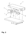
- the laser processing machine 1 for welding linear edges of the box 2 and / or 3 comprises a laser welding optics 4.
- the laser welding optics 4 is displaceable in the direction of a linear axis by means of a hood comprising hood parts 5a and 5b and a guide 6 along a hood guide 7 (see double arrow 8) ). Starting from the basic position, the laser welding optics 4 can be moved to the left side (box 2) or to the right side (box 3).
- the position of the laser welding optics 4 is manually adjustable in terms of angular position and workpiece distance.
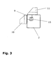
- the tensioning device for the two boxes 2 and 3 essentially comprises a support bar, a plurality of support elements 9 and an upper 10 and a lower clamping bar 11 .
- the support beam on which the support elements 9 are arranged and aligned as individual modules, is in the FIG. 1 hidden and therefore not visible.
- the clamping bars 10 and 11 have recesses 12 which, viewed in the longitudinal direction, are arranged at a predetermined distance from each other.
- the two clamping bars 10 and 11 press the boxes to be processed 2 and 3 against the support elements 9 and against the support bar.
- the recesses 12 are provided for a peripheral edge 13 of the boxes 2 and 3, so that the edge 13 during clamping of the box 2 and 3 can not be damaged.
- the distance between the recesses 12 to each other and the length of the Support elements 9 are matched to each other, so that common protruding edges of boxes or beads or other profiles in the recesses 12 can be positioned.
- the boxes to be processed 2 and 3 can be pushed onto the support beam over the two free ends of the support beam.
- FIG. 1 Not visible in the FIG. 1 is a sensor for detecting the length of the weld.
- the sensor can be used for a calibration cycle.
- the acquired data is stored and used for the further processing programs of the laser processing machine.
- the only parameter that has to be entered manually concerns the material. All other processing parameters can be stored in the machine.
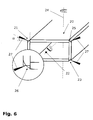
- the invention also relates to a method for welding the longitudinal edges of boxes.
- a box 20 according to Fig. 6 clamped.
- the longitudinal edge 21 is scanned, and the data of the longitudinal edge 21 such as the position and length of the seam are detected and stored.
- the laser processing machine is set to the linear welding of the longitudinal edge 21 and programmed. Since the box is a symmetrically constructed component, the longitudinal edges are the same. Therefore, it is proposed to machine the box 20 having a rectangular cross section as follows: First, the longitudinal edge 21 is welded.
- the box is rotated by 180 ° with respect to the rotation axis 22 determined by the longitudinal center axis. Thereafter, the box 20 is again clamped, and the longitudinal edge 23 is welded with the same assignment of the laser beam to the workpiece (angle, distance) as in the longitudinal edge 21. Subsequently, the box 20 is removed, rotated about a perpendicular to the longitudinal center axis and passing through the center of the workpiece axis of rotation 24 and clamped so that the longitudinal edge 25 can be welded with the same settings of the laser as in the longitudinal edge 21.
- the possibility of "mirroring" is created by a support bar, which allows the support of the box 20 from the left or right free end.
- the box is rotated by 180 ° (rotation axis 22 ). Thereafter, the box 20 is clamped again, and the longitudinal edge 26 is welded with the same settings as in the longitudinal edge 21 (laser beam 27 at an angle ⁇ of about 20 °).
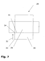
- Fig. 7 illustrates the above-mentioned welding direction (here reference numeral 32 ) from the outside in the direction of the best tensioned box corner.
- a box with a box bottom 29 and box sidewalls 30 can be made from a sheet metal blank 28 .
- the box side walls 30 and the box bottom 29 are folded along a bending line 31 (analogous to the other sides), so that a longitudinal seam to be welded is formed.
- the direction 32 ie, starting from an outer corner 33 in the direction of the box bottom 29 associated corner 34 , to be welded.
Landscapes
- Physics & Mathematics (AREA)
- Optics & Photonics (AREA)
- Engineering & Computer Science (AREA)
- Plasma & Fusion (AREA)
- Mechanical Engineering (AREA)
- Laser Beam Processing (AREA)
Claims (7)
- Machine d'usinage au laser (1) pour produire des joints de soudure linéaires (19 ; 21, 23, 25, 26) sur une pièce (2 ; 3 ; 20) sous la forme d'une caisse ou d'un objet de structure analogue, comprenant :une optique de soudage au laser (4),un support de pièce pour la pièce (2 ; 3 ; 20),ainsi que des moyens de serrage (10, 11) pour serrer la pièce (2 ; 3 ; 20) contre le support de pièce,caractérisée en ce que l'optique de soudage au laser (4) est guidée en déplacement linéaire,en ce que le support de pièce est respectivement formé par au moins un élément de support (9) sur chaque extrémité libre d'une barre de support (15), élément qui s'étend parallèlement à la direction de déplacement (8) de l'optique de soudage au laser (4),et en ce que les moyens de serrage (10, 11) peuvent serrer contre l'élément de support au moins unique (9) la pièce (2 ; 3 ; 20) qui est enfilée par un côté ouvert de la pièce sur l'une ou l'autre des extrémités de la barre et sur l'élément de support au moins unique (9) disposé sur cette extrémité.
- Machine d'usinage au laser selon la revendication 1, caractérisée en ce que les moyens de serrage sont formés par deux barres de serrage (10, 11).
- Machine d'usinage au laser selon l'une des revendications précédentes, caractérisée en ce qu'il est prévu des moyens pour le serrage symétrique de la pièce (2 ; 3 ; 20).
- Machine d'usinage au laser selon l'une des revendications précédentes, caractérisée en ce qu'il est prévu un capteur pour déterminer la longueur du joint de soudure et des moyens pour mémoriser les données déterminées.
- Procédé de soudage au laser de quatre bords longitudinaux (21, 23, 25, 26) d'une pièce (20), avec la succession d'étapes suivante :i) pose de la pièce (20), par un côté ouvert de la pièce, sur une des deux extrémités libres d'une barre de support (15) ;ii) serrage de la pièce (20) contre au moins un élément de support (9) disposé sur l'extrémité de la barre ;iii) réglage d'une optique de soudage au laser (4) quant à sa position angulaire et/ou sa distance par rapport à la pièce (20) ;iv) soudage du premier bord longitudinal (21) ;v) rotation de la pièce (20) de 180° par rapport à un premier axe de rotation (22) défini par son axe médian longitudinal ;vi) soudage du deuxième bord longitudinal (23) ;vii) nouveau serrage de la pièce (20) après sa rotation de 180° par rapport à un deuxième axe de rotation (24) passant par le milieu de la pièce (20) et perpendiculaire à son axe médian longitudinal ;viii) soudage du troisième bord longitudinal (25) ;ix) rotation de la pièce (20) de 180° par rapport au premier axe de rotation (22) ;x) soudage du quatrième bord longitudinal (26).
- Procédé selon la revendication 5, caractérisé en ce qu'on détermine la longueur du joint de soudure.
- Procédé selon la revendication 5 ou 6, caractérisé en ce que l'opération de soudage est effectuée, en partant d'un bord (33) associé à l'ouverture de la pièce - par exemple à l'ouverture de la caisse - qui est opposé à un coin de pièce (34) associé au fond de la pièce, en direction de ce coin de caisse (34).
Priority Applications (2)
| Application Number | Priority Date | Filing Date | Title |
|---|---|---|---|
| EP03021262A EP1516693B1 (fr) | 2003-09-19 | 2003-09-19 | Machine d'usinage laser pour produire des joints soudés linéaires et procédé pour produire des joints soudés linéaire sur des pièces |
| US10/943,140 US20050115934A1 (en) | 2003-09-19 | 2004-09-17 | Laser processing for providing linear weld seams |
Applications Claiming Priority (1)
| Application Number | Priority Date | Filing Date | Title |
|---|---|---|---|
| EP03021262A EP1516693B1 (fr) | 2003-09-19 | 2003-09-19 | Machine d'usinage laser pour produire des joints soudés linéaires et procédé pour produire des joints soudés linéaire sur des pièces |
Publications (2)
| Publication Number | Publication Date |
|---|---|
| EP1516693A1 EP1516693A1 (fr) | 2005-03-23 |
| EP1516693B1 true EP1516693B1 (fr) | 2012-11-07 |
Family
ID=34178446
Family Applications (1)
| Application Number | Title | Priority Date | Filing Date |
|---|---|---|---|
| EP03021262A Expired - Lifetime EP1516693B1 (fr) | 2003-09-19 | 2003-09-19 | Machine d'usinage laser pour produire des joints soudés linéaires et procédé pour produire des joints soudés linéaire sur des pièces |
Country Status (2)
| Country | Link |
|---|---|
| US (1) | US20050115934A1 (fr) |
| EP (1) | EP1516693B1 (fr) |
Cited By (1)
| Publication number | Priority date | Publication date | Assignee | Title |
|---|---|---|---|---|
| CN104625401A (zh) * | 2015-01-21 | 2015-05-20 | 胡和萍 | 一种激光焊接机用轴承固定座装置 |
Families Citing this family (1)
| Publication number | Priority date | Publication date | Assignee | Title |
|---|---|---|---|---|
| CN116586840B (zh) * | 2023-06-02 | 2024-01-16 | 常州市长扬风机有限公司 | 一种变频电机罩壳用焊接装置 |
Family Cites Families (43)
| Publication number | Priority date | Publication date | Assignee | Title |
|---|---|---|---|---|
| US3068351A (en) * | 1959-03-27 | 1962-12-11 | American Mach & Foundry | Welding machine |
| US3268381A (en) * | 1963-10-24 | 1966-08-23 | Ishikawa Kazuo | Method of constructing a plastic container |
| US3473001A (en) * | 1967-04-10 | 1969-10-14 | Airline Welding & Eng | Welding machine carriage and track assembly |
| AT305711B (de) * | 1969-06-06 | 1973-03-12 | Voest Ag | Formrohr |
| US3591757A (en) * | 1970-01-06 | 1971-07-06 | Amf Inc | Welding by high frequency current penetration |
| YU139471A (en) * | 1970-06-11 | 1984-08-31 | Jentsch Hans G | Method of manufcturing bags from multifoil plastics |
| JPS5644187B2 (fr) * | 1973-07-18 | 1981-10-17 | ||
| US3991294A (en) * | 1973-11-13 | 1976-11-09 | The Procter & Gamble Company | Apparatus for making longitudinally partitioned tubular bodies and container assemblies |
| US3937914A (en) * | 1974-08-02 | 1976-02-10 | Thermatool Corporation | Method and apparatus for manufacturing welded metal tubes of finite length |
| US3958098A (en) * | 1974-09-03 | 1976-05-18 | Sumitomo Shipbuilding & Machinery Co., Ltd. | Apparatus for automatic and vertical fillet welding |
| FR2338766A1 (fr) * | 1976-01-20 | 1977-08-19 | Saurin Emmanuel | Procede de fabrication d'une boite de conserve et dispositif pour l'execution de ce procede |
| US4176269A (en) * | 1976-02-03 | 1979-11-27 | Merrick Welding International, Inc. | Clamping apparatus for welding circumferential articles |
| US4101752A (en) * | 1976-09-15 | 1978-07-18 | Westinghouse Electric Corp. | Process for welding corner cells in fuel assembly grids |
| US4088890A (en) * | 1976-09-28 | 1978-05-09 | United Technologies Corporation | Optical position detector |
| US4301911A (en) * | 1979-07-18 | 1981-11-24 | Pneumatic Scale Corporation | Apparatus for handling a tubular carton blank |
| US4369957A (en) * | 1981-08-03 | 1983-01-25 | Williams Stanley B | Device for clamping and aligning plates to be joined in selected angular relationship |
| JPS5885083A (ja) * | 1981-11-13 | 1983-05-21 | 株式会社東芝 | 冷蔵庫扉の製造方法 |
| US4541055A (en) * | 1982-09-01 | 1985-09-10 | Westinghouse Electric Corp. | Laser machining system |
| US4538956A (en) * | 1982-09-01 | 1985-09-03 | Westinghouse Electric Corp. | Workpiece gripping and manipulating apparatus for laser welding systems and the like |
| US4492844A (en) * | 1982-09-01 | 1985-01-08 | Westinghouse Electric Corp. | Welding plates for a fuel rod grid |
| US4500488A (en) * | 1982-09-07 | 1985-02-19 | The United States Of America As Represented By The United States Department Of Energy | Encapsulated fuel unit and method of forming same |
| US4574176A (en) * | 1983-11-28 | 1986-03-04 | Sws Incorporated | Method and apparatus for pulsed high energy density welding |
| JPS62104689A (ja) * | 1984-02-29 | 1987-05-15 | エルパトロ−ニク・アクチエンゲゼルシヤフト | かん円筒部の縦縁をレ−ザ溶接するための装置 |
| US4639574A (en) * | 1984-10-19 | 1987-01-27 | Ductmate Industries, Inc. | Automatic duct welding machine |
| US4745259A (en) * | 1986-07-21 | 1988-05-17 | Russ Wray H | Automatic corner welding adapter |
| DE3630889A1 (de) * | 1986-09-11 | 1988-03-24 | Krupp Gmbh | Verfahren zum laengsnahtschweissen von behaelterruempfen mittels laserstrahl und vorrichtung zur durchfuehrung des verfahrens |
| US4829741A (en) * | 1986-09-12 | 1989-05-16 | Langen Research B.V. | Apparatus for packing and processing a meat product |
| US4977512A (en) * | 1987-02-05 | 1990-12-11 | Shibuya Kogyo Co., Ltd. | Three dimensional simultaneous machining and measuring system |
| US5005801A (en) * | 1989-08-18 | 1991-04-09 | Giarrocco Iii Martin A | Jack hanging apparatus |
| FR2694714B1 (fr) * | 1992-08-14 | 1994-11-10 | Lorraine Laminage | Installation d'accostage et de soudage bord à bord en continu d'au moins deux flans de tôle au moyen d'un faisceau laser. |
| US5533399A (en) * | 1992-09-30 | 1996-07-09 | Wayne State University | Method and apparatus for non-destructive measurement of elastic properties of structural materials |
| US5851248A (en) * | 1992-10-02 | 1998-12-22 | Nordson Corporation | Filter cartridge assembly for powder coating booth and collection system |
| US5385628A (en) * | 1993-03-24 | 1995-01-31 | Davis; Roland | Gasket welding apparatus and method |
| US5494553A (en) * | 1993-09-20 | 1996-02-27 | Colucci; William G. | Multi-purpose clamping apparatus |
| US5500503A (en) * | 1994-08-04 | 1996-03-19 | Midwest Research Institute | Simultaneous laser cutting and welding of metal foil to edge of a plate |
| US5674420A (en) * | 1995-06-12 | 1997-10-07 | Worthington Industries Incorporated | Clamping device for welding machine |
| US5772233A (en) * | 1996-04-09 | 1998-06-30 | Decoma International Inc. | Expandable painting wagon |
| EP0803313A3 (fr) * | 1996-04-23 | 2000-01-12 | Daido Tokushuko Kabushiki Kaisha | Procédé et dispositif pour lier par diffusion |
| US6080961A (en) * | 1996-10-31 | 2000-06-27 | Nissan Motor Co., Ltd. | Blank material positioning device and blank material positioning method |
| US6024024A (en) * | 1998-04-02 | 2000-02-15 | Favaretto; Paolo | Table structure |
| US6079187A (en) * | 1998-12-01 | 2000-06-27 | Hart & Cooley, Inc. | Apparatus for packaging flexible duct for shipment and method for performing the same |
| CA2384155C (fr) * | 1999-09-10 | 2006-11-21 | Amweld Building Products, Llc | Realisation de porte et procede associe |
| WO2003064115A1 (fr) * | 2002-01-30 | 2003-08-07 | Wolfcraft Gmbh | Support pliable pour scie pendulaire |
-
2003
- 2003-09-19 EP EP03021262A patent/EP1516693B1/fr not_active Expired - Lifetime
-
2004
- 2004-09-17 US US10/943,140 patent/US20050115934A1/en not_active Abandoned
Cited By (1)
| Publication number | Priority date | Publication date | Assignee | Title |
|---|---|---|---|---|
| CN104625401A (zh) * | 2015-01-21 | 2015-05-20 | 胡和萍 | 一种激光焊接机用轴承固定座装置 |
Also Published As
| Publication number | Publication date |
|---|---|
| EP1516693A1 (fr) | 2005-03-23 |
| US20050115934A1 (en) | 2005-06-02 |
Similar Documents
| Publication | Publication Date | Title |
|---|---|---|
| EP3391987B1 (fr) | Procédé de soudage de parties de tôles découpées | |
| EP1838492B1 (fr) | Installation de production et procede d'assemblage de pieces | |
| EP2377639B1 (fr) | Machine pour l'usinage par laser de pièces planes ou cylindriques ; Procédé de rééquipement d'une telle machine | |
| DE4431384A1 (de) | Vorrichtung zum Umrahmen von Fahrzeugkörpern | |
| AT523568B1 (de) | Biegemaschine | |
| EP2285522A1 (fr) | Machine d'usinage au laser avec espace de travail étendu | |
| EP3528996B1 (fr) | Procédé permettant de prévoir une tendance au basculement d'une partie de pièce découpée et machine d'usinage pour l'usinage par découpage d'une pièce en forme de plaque | |
| DE19853366B4 (de) | Vorrichtung und Verfahren zum Umformen | |
| EP4408605B1 (fr) | Dispositif et procédé de soudage au laser de plaques d'acier | |
| EP3515618B1 (fr) | Outil et machine-outil ainsi que procédé pour usiner des pièces en forme de panneaux | |
| WO2018055193A1 (fr) | Outil, machine-outil et procédé d'usinage de pièces en forme de plaque | |
| WO2018091536A1 (fr) | Soudage par pression laser | |
| DE10135233A1 (de) | Ringmaschine | |
| EP3302840B1 (fr) | Installation de fabrication pour la fabrication de pièces en tôle et procédé à cet effet | |
| EP1516693B1 (fr) | Machine d'usinage laser pour produire des joints soudés linéaires et procédé pour produire des joints soudés linéaire sur des pièces | |
| EP3746288B1 (fr) | Dispositif d'assemblage, en particulier de soudage au laser, de deux pièces, et procédé permettant de faire fonctionner ledit dispositif | |
| WO2018055183A1 (fr) | Outil et machine-outil et procédé de traitement de pièces en forme de plaques | |
| EP1346792A1 (fr) | Appareil de soudage | |
| EP1128929A1 (fr) | Procede et dispositif pour la fabrication de platines soudees | |
| EP0743135A2 (fr) | Procédé de jonction de deux pièces | |
| DE102018105661A1 (de) | Beförderungssystem | |
| DE10029293A1 (de) | Vorrichtung und Verfahren zum Laserstrahlschweißen von Blechplatinen | |
| EP3331685B1 (fr) | Dispositif de montage | |
| DE3536015A1 (de) | Fertigungsstation, insbesondere fuer kraftfahrzeug-karosserien | |
| AT514788B1 (de) | Biegewerkzeug aus mehreren Werkzeugelementen |
Legal Events
| Date | Code | Title | Description |
|---|---|---|---|
| PUAI | Public reference made under article 153(3) epc to a published international application that has entered the european phase |
Free format text: ORIGINAL CODE: 0009012 |
|
| AK | Designated contracting states |
Kind code of ref document: A1 Designated state(s): AT BE BG CH CY CZ DE DK EE ES FI FR GB GR HU IE IT LI LU MC NL PT RO SE SI SK TR |
|
| AX | Request for extension of the european patent |
Extension state: AL LT LV MK |
|
| 17P | Request for examination filed |
Effective date: 20050831 |
|
| AKX | Designation fees paid |
Designated state(s): AT BE BG CH CY CZ DE DK EE ES FI FR GB GR HU IE IT LI LU MC NL PT RO SE SI SK TR |
|
| GRAP | Despatch of communication of intention to grant a patent |
Free format text: ORIGINAL CODE: EPIDOSNIGR1 |
|
| GRAS | Grant fee paid |
Free format text: ORIGINAL CODE: EPIDOSNIGR3 |
|
| GRAA | (expected) grant |
Free format text: ORIGINAL CODE: 0009210 |
|
| AK | Designated contracting states |
Kind code of ref document: B1 Designated state(s): AT BE BG CH CY CZ DE DK EE ES FI FR GB GR HU IE IT LI LU MC NL PT RO SE SI SK TR |
|
| REG | Reference to a national code |
Ref country code: GB Ref legal event code: FG4D Free format text: NOT ENGLISH |
|
| REG | Reference to a national code |
Ref country code: CH Ref legal event code: EP Ref country code: AT Ref legal event code: REF Ref document number: 582784 Country of ref document: AT Kind code of ref document: T Effective date: 20121115 |
|
| REG | Reference to a national code |
Ref country code: IE Ref legal event code: FG4D Free format text: LANGUAGE OF EP DOCUMENT: GERMAN |
|
| REG | Reference to a national code |
Ref country code: DE Ref legal event code: R096 Ref document number: 50314575 Country of ref document: DE Effective date: 20130103 |
|
| REG | Reference to a national code |
Ref country code: NL Ref legal event code: VDEP Effective date: 20121107 |
|
| PG25 | Lapsed in a contracting state [announced via postgrant information from national office to epo] |
Ref country code: SE Free format text: LAPSE BECAUSE OF FAILURE TO SUBMIT A TRANSLATION OF THE DESCRIPTION OR TO PAY THE FEE WITHIN THE PRESCRIBED TIME-LIMIT Effective date: 20121107 Ref country code: NL Free format text: LAPSE BECAUSE OF FAILURE TO SUBMIT A TRANSLATION OF THE DESCRIPTION OR TO PAY THE FEE WITHIN THE PRESCRIBED TIME-LIMIT Effective date: 20121107 Ref country code: ES Free format text: LAPSE BECAUSE OF FAILURE TO SUBMIT A TRANSLATION OF THE DESCRIPTION OR TO PAY THE FEE WITHIN THE PRESCRIBED TIME-LIMIT Effective date: 20130218 Ref country code: FI Free format text: LAPSE BECAUSE OF FAILURE TO SUBMIT A TRANSLATION OF THE DESCRIPTION OR TO PAY THE FEE WITHIN THE PRESCRIBED TIME-LIMIT Effective date: 20121107 |
|
| PG25 | Lapsed in a contracting state [announced via postgrant information from national office to epo] |
Ref country code: CY Free format text: LAPSE BECAUSE OF FAILURE TO SUBMIT A TRANSLATION OF THE DESCRIPTION OR TO PAY THE FEE WITHIN THE PRESCRIBED TIME-LIMIT Effective date: 20121107 Ref country code: SI Free format text: LAPSE BECAUSE OF FAILURE TO SUBMIT A TRANSLATION OF THE DESCRIPTION OR TO PAY THE FEE WITHIN THE PRESCRIBED TIME-LIMIT Effective date: 20121107 Ref country code: PT Free format text: LAPSE BECAUSE OF FAILURE TO SUBMIT A TRANSLATION OF THE DESCRIPTION OR TO PAY THE FEE WITHIN THE PRESCRIBED TIME-LIMIT Effective date: 20130307 Ref country code: GR Free format text: LAPSE BECAUSE OF FAILURE TO SUBMIT A TRANSLATION OF THE DESCRIPTION OR TO PAY THE FEE WITHIN THE PRESCRIBED TIME-LIMIT Effective date: 20130208 |
|
| PG25 | Lapsed in a contracting state [announced via postgrant information from national office to epo] |
Ref country code: SK Free format text: LAPSE BECAUSE OF FAILURE TO SUBMIT A TRANSLATION OF THE DESCRIPTION OR TO PAY THE FEE WITHIN THE PRESCRIBED TIME-LIMIT Effective date: 20121107 Ref country code: DK Free format text: LAPSE BECAUSE OF FAILURE TO SUBMIT A TRANSLATION OF THE DESCRIPTION OR TO PAY THE FEE WITHIN THE PRESCRIBED TIME-LIMIT Effective date: 20121107 Ref country code: EE Free format text: LAPSE BECAUSE OF FAILURE TO SUBMIT A TRANSLATION OF THE DESCRIPTION OR TO PAY THE FEE WITHIN THE PRESCRIBED TIME-LIMIT Effective date: 20121107 Ref country code: BG Free format text: LAPSE BECAUSE OF FAILURE TO SUBMIT A TRANSLATION OF THE DESCRIPTION OR TO PAY THE FEE WITHIN THE PRESCRIBED TIME-LIMIT Effective date: 20130207 Ref country code: CZ Free format text: LAPSE BECAUSE OF FAILURE TO SUBMIT A TRANSLATION OF THE DESCRIPTION OR TO PAY THE FEE WITHIN THE PRESCRIBED TIME-LIMIT Effective date: 20121107 |
|
| PG25 | Lapsed in a contracting state [announced via postgrant information from national office to epo] |
Ref country code: RO Free format text: LAPSE BECAUSE OF FAILURE TO SUBMIT A TRANSLATION OF THE DESCRIPTION OR TO PAY THE FEE WITHIN THE PRESCRIBED TIME-LIMIT Effective date: 20121107 |
|
| PLBE | No opposition filed within time limit |
Free format text: ORIGINAL CODE: 0009261 |
|
| STAA | Information on the status of an ep patent application or granted ep patent |
Free format text: STATUS: NO OPPOSITION FILED WITHIN TIME LIMIT |
|
| 26N | No opposition filed |
Effective date: 20130808 |
|
| REG | Reference to a national code |
Ref country code: DE Ref legal event code: R097 Ref document number: 50314575 Country of ref document: DE Effective date: 20130808 |
|
| BERE | Be: lapsed |
Owner name: TRUMPF LASER- UND SYSTEMTECHNIK G.M.B.H. Effective date: 20130930 |
|
| PG25 | Lapsed in a contracting state [announced via postgrant information from national office to epo] |
Ref country code: MC Free format text: LAPSE BECAUSE OF FAILURE TO SUBMIT A TRANSLATION OF THE DESCRIPTION OR TO PAY THE FEE WITHIN THE PRESCRIBED TIME-LIMIT Effective date: 20121107 |
|
| REG | Reference to a national code |
Ref country code: CH Ref legal event code: PL |
|
| GBPC | Gb: european patent ceased through non-payment of renewal fee |
Effective date: 20130919 |
|
| REG | Reference to a national code |
Ref country code: IE Ref legal event code: MM4A |
|
| PG25 | Lapsed in a contracting state [announced via postgrant information from national office to epo] |
Ref country code: IE Free format text: LAPSE BECAUSE OF NON-PAYMENT OF DUE FEES Effective date: 20130919 Ref country code: CH Free format text: LAPSE BECAUSE OF NON-PAYMENT OF DUE FEES Effective date: 20130930 Ref country code: LI Free format text: LAPSE BECAUSE OF NON-PAYMENT OF DUE FEES Effective date: 20130930 Ref country code: GB Free format text: LAPSE BECAUSE OF NON-PAYMENT OF DUE FEES Effective date: 20130919 Ref country code: BE Free format text: LAPSE BECAUSE OF NON-PAYMENT OF DUE FEES Effective date: 20130930 |
|
| REG | Reference to a national code |
Ref country code: AT Ref legal event code: MM01 Ref document number: 582784 Country of ref document: AT Kind code of ref document: T Effective date: 20130919 |
|
| PG25 | Lapsed in a contracting state [announced via postgrant information from national office to epo] |
Ref country code: AT Free format text: LAPSE BECAUSE OF NON-PAYMENT OF DUE FEES Effective date: 20130919 |
|
| PG25 | Lapsed in a contracting state [announced via postgrant information from national office to epo] |
Ref country code: TR Free format text: LAPSE BECAUSE OF FAILURE TO SUBMIT A TRANSLATION OF THE DESCRIPTION OR TO PAY THE FEE WITHIN THE PRESCRIBED TIME-LIMIT Effective date: 20121107 |
|
| PG25 | Lapsed in a contracting state [announced via postgrant information from national office to epo] |
Ref country code: LU Free format text: LAPSE BECAUSE OF NON-PAYMENT OF DUE FEES Effective date: 20130919 Ref country code: HU Free format text: LAPSE BECAUSE OF FAILURE TO SUBMIT A TRANSLATION OF THE DESCRIPTION OR TO PAY THE FEE WITHIN THE PRESCRIBED TIME-LIMIT; INVALID AB INITIO Effective date: 20030919 |
|
| REG | Reference to a national code |
Ref country code: FR Ref legal event code: PLFP Year of fee payment: 14 |
|
| REG | Reference to a national code |
Ref country code: FR Ref legal event code: PLFP Year of fee payment: 15 |
|
| REG | Reference to a national code |
Ref country code: FR Ref legal event code: PLFP Year of fee payment: 16 |
|
| PGFP | Annual fee paid to national office [announced via postgrant information from national office to epo] |
Ref country code: IT Payment date: 20210922 Year of fee payment: 19 Ref country code: FR Payment date: 20210921 Year of fee payment: 19 |
|
| PGFP | Annual fee paid to national office [announced via postgrant information from national office to epo] |
Ref country code: DE Payment date: 20210920 Year of fee payment: 19 |
|
| REG | Reference to a national code |
Ref country code: DE Ref legal event code: R119 Ref document number: 50314575 Country of ref document: DE |
|
| PG25 | Lapsed in a contracting state [announced via postgrant information from national office to epo] |
Ref country code: FR Free format text: LAPSE BECAUSE OF NON-PAYMENT OF DUE FEES Effective date: 20220930 Ref country code: DE Free format text: LAPSE BECAUSE OF NON-PAYMENT OF DUE FEES Effective date: 20230401 |
|
| PG25 | Lapsed in a contracting state [announced via postgrant information from national office to epo] |
Ref country code: IT Free format text: LAPSE BECAUSE OF NON-PAYMENT OF DUE FEES Effective date: 20220919 |