EP1516693B1 - Laser machining machine for producing linear welding seams and process for producing linear welding seams onto a workpiece - Google Patents
Laser machining machine for producing linear welding seams and process for producing linear welding seams onto a workpiece Download PDFInfo
- Publication number
- EP1516693B1 EP1516693B1 EP03021262A EP03021262A EP1516693B1 EP 1516693 B1 EP1516693 B1 EP 1516693B1 EP 03021262 A EP03021262 A EP 03021262A EP 03021262 A EP03021262 A EP 03021262A EP 1516693 B1 EP1516693 B1 EP 1516693B1
- Authority
- EP
- European Patent Office
- Prior art keywords
- workpiece
- clamping
- support
- welding
- box
- Prior art date
- Legal status (The legal status is an assumption and is not a legal conclusion. Google has not performed a legal analysis and makes no representation as to the accuracy of the status listed.)
- Expired - Lifetime
Links
Images


Classifications
-
- B—PERFORMING OPERATIONS; TRANSPORTING
- B23—MACHINE TOOLS; METAL-WORKING NOT OTHERWISE PROVIDED FOR
- B23K—SOLDERING OR UNSOLDERING; WELDING; CLADDING OR PLATING BY SOLDERING OR WELDING; CUTTING BY APPLYING HEAT LOCALLY, e.g. FLAME CUTTING; WORKING BY LASER BEAM
- B23K26/00—Working by laser beam, e.g. welding, cutting or boring
- B23K26/08—Devices involving relative movement between laser beam and workpiece
- B23K26/0823—Devices involving rotation of the workpiece
-
- B—PERFORMING OPERATIONS; TRANSPORTING
- B23—MACHINE TOOLS; METAL-WORKING NOT OTHERWISE PROVIDED FOR
- B23K—SOLDERING OR UNSOLDERING; WELDING; CLADDING OR PLATING BY SOLDERING OR WELDING; CUTTING BY APPLYING HEAT LOCALLY, e.g. FLAME CUTTING; WORKING BY LASER BEAM
- B23K26/00—Working by laser beam, e.g. welding, cutting or boring
- B23K26/20—Bonding
- B23K26/21—Bonding by welding
- B23K26/24—Seam welding
- B23K26/26—Seam welding of rectilinear seams
- B23K26/262—Seam welding of rectilinear seams of longitudinal seams of tubes
Definitions
- the invention relates to a laser processing machine for producing linear welds on a workpiece according to the preamble of patent claim 1 and a method for laser welding of four longitudinal edges of a workpiece.
- Such a laser processing machine is, for example, by the US-A-4541055 known.
- a high proportion of workpieces to be welded industrially are housing parts or boxes with linear welding edges in small and medium batch sizes.
- the heat conduction welding is usually desirable for these workpieces, so that post-processing seams can be produced.
- the sheet metal edges to be welded usually arise from sheet metal sides meeting each other at right angles.
- the conditions at a plurality of longitudinal edges can be identical to a workpiece and symmetrical to a plane parallel to the edges to be welded.
- boxes of rectangular cross section are constructed symmetrically to a longitudinal center plane.
- the seams are also straight. Often have the housing parts to be welded on a circumferential edge or beads.
- the welding optics must be converted during the processing of different longitudinal edges of the workpiece.
- the from the above US-A-4541055 known laser processing machine is used to generate linear welds on a workpiece and includes a laser welding optics, a workpiece support and clamping means for clamping the workpiece against the workpiece support.
- the laser welding optics is fixed immovably and the workpiece support in the XY plane slidably mounted.
- the workpiece support is formed by a rotatable support table, on which the workpiece is mounted on the resting.
- the Applicant has therefore set itself the task of providing a laser processing machine of the type mentioned and a method for easy welding of longitudinal edges of a workpiece, in particular of boxes and housing parts.
- the invention encompasses any type of relative movement between the workpiece and the laser welding optics. Particularly advantageous is the linear movement of the laser welding optics. But also a movement of the workpiece is conceivable.
- the means for clamping can be formed by two clamping bars.
- the invention allows the processing of boxes or housing parts.
- the individual support elements can be matched in terms of their geometry to the geometry of the long sides of the boxes or the housing parts in the region of the longitudinal edge.
- the workpiece to be machined can be optimally tensioned. Circumferential edges of the workpiece can be clamped without damage. This can be done by the positioning of the support elements taking into account the peripheral edge. It can also be provided corresponding recesses in the support elements and / or clamping bars.
- the mirror-symmetric clamping of a workpiece i. the re-tightening after rotation with respect to a transverse to the longitudinal center axis (thus also transverse to the weld) and extending through the center of the workpiece axis of rotation.
- the laying of the workpiece, starting from the two free ends of the support beam, allows this mirror-symmetrical clamping a box or the like.
- the invention therefore, in isolation, a device and a method for mirror-symmetrical machining of the workpiece.
- a sensor for detecting the weld seam length and means for storing the acquired data be provided.
- the sensor or a video camera and an image processing system thus detect individual weld parameters. If, for example, the seam length is detected and stored by the calibration process and further known parameters such as the material are entered, the welding process can proceed largely automatically.
- the laser processing machine according to the invention can advantageously be integrated into a laser processing network.
- a so-called laser processing network it is possible to crosslink one or more solid-state lasers with different processing stations, one of which may be the laser processing machine according to the teachings of the invention.
- the workstations request the required laser energy from the laser devices integrated in the network.
- the aim is the safe and intelligent distribution of laser energy without power and beam quality restrictions and thus optimization of the utilization and availability of a laser device.
- the availability of the entire system is increased by the simple implementation of redundancy concepts
- the method enables economical processing of boxes or the like.
- a corresponding device for carrying out the method is therefore also regarded as an independent invention.
- a sensor for detecting the weld seam length can be provided. This has the advantage that an even greater degree of automation can be achieved.
- the welding is based on one of the workpiece opening, such as the box opening, associated edge, which is opposite to the workpiece bottom associated workpiece corner, in the direction of this workpiece corner.
- This workpiece corner represents the best tensioned part of the workpiece. This results in an increased precision in the machining of the workpiece is achieved.
- the embodiment relates to a box with peripheral edge.
- the laser processing machine 1 can also be used to machine a similarly constructed object, for example a housing part, with linear edges to be welded.
- the laser processing machine 1 for welding linear edges of the box 2 and / or 3 comprises a laser welding optics 4.
- the laser welding optics 4 is displaceable in the direction of a linear axis by means of a hood comprising hood parts 5a and 5b and a guide 6 along a hood guide 7 (see double arrow 8) ). Starting from the basic position, the laser welding optics 4 can be moved to the left side (box 2) or to the right side (box 3).
- the position of the laser welding optics 4 is manually adjustable in terms of angular position and workpiece distance.
- the tensioning device for the two boxes 2 and 3 essentially comprises a support bar, a plurality of support elements 9 and an upper 10 and a lower clamping bar 11 .
- the support beam on which the support elements 9 are arranged and aligned as individual modules, is in the FIG. 1 hidden and therefore not visible.
- the clamping bars 10 and 11 have recesses 12 which, viewed in the longitudinal direction, are arranged at a predetermined distance from each other.
- the two clamping bars 10 and 11 press the boxes to be processed 2 and 3 against the support elements 9 and against the support bar.
- the recesses 12 are provided for a peripheral edge 13 of the boxes 2 and 3, so that the edge 13 during clamping of the box 2 and 3 can not be damaged.
- the distance between the recesses 12 to each other and the length of the Support elements 9 are matched to each other, so that common protruding edges of boxes or beads or other profiles in the recesses 12 can be positioned.
- the boxes to be processed 2 and 3 can be pushed onto the support beam over the two free ends of the support beam.
- FIG. 1 Not visible in the FIG. 1 is a sensor for detecting the length of the weld.
- the sensor can be used for a calibration cycle.
- the acquired data is stored and used for the further processing programs of the laser processing machine.
- the only parameter that has to be entered manually concerns the material. All other processing parameters can be stored in the machine.
- the invention also relates to a method for welding the longitudinal edges of boxes.
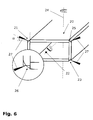
- a box 20 according to Fig. 6 clamped.
- the longitudinal edge 21 is scanned, and the data of the longitudinal edge 21 such as the position and length of the seam are detected and stored.
- the laser processing machine is set to the linear welding of the longitudinal edge 21 and programmed. Since the box is a symmetrically constructed component, the longitudinal edges are the same. Therefore, it is proposed to machine the box 20 having a rectangular cross section as follows: First, the longitudinal edge 21 is welded.
- the box is rotated by 180 ° with respect to the rotation axis 22 determined by the longitudinal center axis. Thereafter, the box 20 is again clamped, and the longitudinal edge 23 is welded with the same assignment of the laser beam to the workpiece (angle, distance) as in the longitudinal edge 21. Subsequently, the box 20 is removed, rotated about a perpendicular to the longitudinal center axis and passing through the center of the workpiece axis of rotation 24 and clamped so that the longitudinal edge 25 can be welded with the same settings of the laser as in the longitudinal edge 21.
- the possibility of "mirroring" is created by a support bar, which allows the support of the box 20 from the left or right free end.
- the box is rotated by 180 ° (rotation axis 22 ). Thereafter, the box 20 is clamped again, and the longitudinal edge 26 is welded with the same settings as in the longitudinal edge 21 (laser beam 27 at an angle ⁇ of about 20 °).
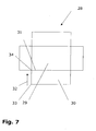
- Fig. 7 illustrates the above-mentioned welding direction (here reference numeral 32 ) from the outside in the direction of the best tensioned box corner.
- a box with a box bottom 29 and box sidewalls 30 can be made from a sheet metal blank 28 .
- the box side walls 30 and the box bottom 29 are folded along a bending line 31 (analogous to the other sides), so that a longitudinal seam to be welded is formed.
- the direction 32 ie, starting from an outer corner 33 in the direction of the box bottom 29 associated corner 34 , to be welded.
Landscapes
- Physics & Mathematics (AREA)
- Optics & Photonics (AREA)
- Engineering & Computer Science (AREA)
- Plasma & Fusion (AREA)
- Mechanical Engineering (AREA)
- Laser Beam Processing (AREA)
Description
Die Erfindung betrifft eine Laserbearbeitungsmaschine zum Erzeugen linearer Schweißnähte an einem Werkstück gemäß dem Oberbegriff von Patantanspruch 1 und ein Verfahren zum Laserschweißen von vier Längskanten eines Werkstücks.The invention relates to a laser processing machine for producing linear welds on a workpiece according to the preamble of
Eine derartige Laserbearbeitungsmaschine ist beispielsweise durch die
Ein hoher Anteil der industriell zu schweißenden Werkstücke sind Gehäuseteile oder Kisten mit linearen Schweißkanten in kleinen und mittleren Losgrößen. Als Schweißverfahren ist für diese Werkstücke in der Regel das Wärmeleitungsschweißen erwünscht, so dass nacharbeitungsfreie Nähte erzeugt werden können.A high proportion of workpieces to be welded industrially are housing parts or boxes with linear welding edges in small and medium batch sizes. As a welding method, the heat conduction welding is usually desirable for these workpieces, so that post-processing seams can be produced.
Die zu verschweißenden Blechkanten entstehen meist durch rechtwinklig aufeinander treffende Blechseiten. Die Verhältnisse an mehreren Längskanten können an einem Werkstück identisch und symmetrisch zu einer Ebene parallel zu den zu verschweißenden Kanten sein. Beispielsweise sind Kisten rechteckigen Querschnitts symmetrisch zu einer Längsmittenebene aufgebaut. Die Nähte verlaufen zudem geradlinig. Häufig weisen die zu verschweißenden Gehäuseteile einen umlaufenden Rand oder Sicken auf.The sheet metal edges to be welded usually arise from sheet metal sides meeting each other at right angles. The conditions at a plurality of longitudinal edges can be identical to a workpiece and symmetrical to a plane parallel to the edges to be welded. For example, boxes of rectangular cross section are constructed symmetrically to a longitudinal center plane. The seams are also straight. Often have the housing parts to be welded on a circumferential edge or beads.
Derzeit müssen für diese Werkstücke meist aufwändige Spannvorrichtungen gebaut werden, die auf die jeweilige Bearbeitungsaufgabe bzw. das jeweilige Bauteil abgestimmt sind. Bei der Auslegung einer geeigneten Spannvorrichtung sind insbesondere umlaufende Ränder, Falze oder sonstige Umformungen zu berücksichtigen, die beim Einspannen nicht beschädigt werden dürfen.Currently, usually elaborate fixtures must be built for these workpieces, which are tailored to the respective machining task or the respective component. In the design of a suitable clamping device, in particular peripheral edges, folds or other deformations are to be considered, which must not be damaged during clamping.
Alternativ oder ergänzend dazu muss die Schweißoptik während der Bearbeitung verschiedener Längskanten des Werkstücks umgerüstet werden.Alternatively or additionally, the welding optics must be converted during the processing of different longitudinal edges of the workpiece.
Die aus der eingangs genannten
Der Anmelder hat sich daher die Aufgabe gestellt, eine Laserbearbeitungsmaschine der eingangs genannten Art und ein Verfahrens zum einfachen Schweißen von Längskanten eines Werkstücks, insbesondere von Kisten und Gehäuseteilen, bereitzustellen.The Applicant has therefore set itself the task of providing a laser processing machine of the type mentioned and a method for easy welding of longitudinal edges of a workpiece, in particular of boxes and housing parts.
Diese Aufgabe wird durch eine Laserbearbeitungsmaschine mit den Merkmalen von Patentanspüruch 1 gelöst. Die modular aufgebaute Spannvorrichtung führt zu einem leicht handhabbaren und kostengünstigen Spannen von Werkstücken.This object is achieved by a laser processing machine with the features of Patentanspüruch 1. The modular clamping device leads to an easy-to-handle and cost-effective clamping of workpieces.
Von der Erfindung wird jede Art der Relativbewegung zwischen Werkstück und Laserschweißoptik umfasst. Besonders vorteilhaft ist die Linearbewegung der Laserschweißoptik. Aber auch eine Bewegung des Werkstücks ist denkbar.The invention encompasses any type of relative movement between the workpiece and the laser welding optics. Particularly advantageous is the linear movement of the laser welding optics. But also a movement of the workpiece is conceivable.
In einfacher kompakter Ausgestaltung können die Mittel zum Spannen durch zwei Spannbalken ausgebildet sein.In a simple compact design, the means for clamping can be formed by two clamping bars.
Die Erfindung erlaubt die Bearbeitung von Kisten oder Gehäuseteilen. Die einzelnen Auflageelemente können hinsichtlich ihrer Geometrie auf die Geometrie der Längsseiten der Kisten oder der Gehäuseteile im Bereich der Längskante abgestimmt sein. Durch eine geeignete Auswahl auch hinsichtlich der Anzahl und der Gestaltung der Auflageelemente kann das zu bearbeitende Werkstück optimal gespannt werden. Umlaufende Ränder des Werkstücks können beschädigungsfrei eingespannt werden. Dies kann durch die Positionierung der Auflageelemente unter Berücksichtigung des umlaufenden Randes geschehen. Es können auch entsprechende Ausnehmungen in den Auflageelementen und/oder Spannbalken vorgesehen sein.The invention allows the processing of boxes or housing parts. The individual support elements can be matched in terms of their geometry to the geometry of the long sides of the boxes or the housing parts in the region of the longitudinal edge. By a suitable selection, also with regard to the number and the design of the support elements, the workpiece to be machined can be optimally tensioned. Circumferential edges of the workpiece can be clamped without damage. This can be done by the positioning of the support elements taking into account the peripheral edge. It can also be provided corresponding recesses in the support elements and / or clamping bars.
Bevorzugt ist das spiegelsymmetrische Spannen eines Werkstücks, d.h. das erneute Spannen nach einer Drehung bezüglich einer quer zur Längsmittenachse (somit auch quer zur Schweißnaht) und durch die Mitte des Werkstücks verlaufenden Drehachse. Das Auflegen des Werkstücks, ausgehend von den beiden freien Enden des Auflagebalkens, ermöglicht dieses spiegelsymmetrische Spannen einer Kiste oder dergleichen. Gegenstand der Erfindung sind daher in Alleinstellung auch eine Vorrichtung und ein Verfahren zur spiegelsymmetrischen Bearbeitung des Werkstücks.Preferably, the mirror-symmetric clamping of a workpiece, i. the re-tightening after rotation with respect to a transverse to the longitudinal center axis (thus also transverse to the weld) and extending through the center of the workpiece axis of rotation. The laying of the workpiece, starting from the two free ends of the support beam, allows this mirror-symmetrical clamping a box or the like. The invention, therefore, in isolation, a device and a method for mirror-symmetrical machining of the workpiece.
In Weiterbildung der Erfindung können ein Sensor zur Erfassung der Schweißnahtlänge und Mittel zur Speicherung der erfassten Daten vorgesehen sein. Der Sensor oder eine Videokamera und ein Bildverarbeitungssystem erfassen somit einzelne Schweißnahtparameter. Wenn beispielsweise die Nahtlänge durch den Kalibriervorgang erfasst und gespeichert sowie weitere bekannte Parameter wie der Werkstoff eingegeben werden, kann der Schweißvorgang weitgehend automatisch ablaufen.In a further development of the invention, a sensor for detecting the weld seam length and means for storing the acquired data be provided. The sensor or a video camera and an image processing system thus detect individual weld parameters. If, for example, the seam length is detected and stored by the calibration process and further known parameters such as the material are entered, the welding process can proceed largely automatically.
Die erfindungsgemäße Laserbearbeitungsmaschine kann vorteilhafter Weise in ein Laserbearbeitungsnetzwerk integriert werden. Mithilfe eines sog. Laserbearbeitungsnetzwerks ist es möglich, einen oder mehrere Festkörperlaser mit verschiedenen Bearbeitungsstationen, von denen eine die Laserbearbeitungsmaschine gemäß der Lehre der Erfindung sein kann, zu vernetzen. Im schnellen Wechsel fordern die Arbeitsstationen die benötigte Laserenergie von den im Netzwerk eingebundenen Lasergeräten an. Ziel ist die sichere und intelligente Verteilung der Laserenergie ohne Leistungs- und Strahlqualitätseinschränkungen und damit Optimierung der Auslastung und Verfügbarkeit eines Lasergerätes. Die Verfügbarkeit der Gesamtanlage wird durch die einfache Umsetzung von Redundanzkonzepten gesteigertThe laser processing machine according to the invention can advantageously be integrated into a laser processing network. By means of a so-called laser processing network, it is possible to crosslink one or more solid-state lasers with different processing stations, one of which may be the laser processing machine according to the teachings of the invention. In rapid change, the workstations request the required laser energy from the laser devices integrated in the network. The aim is the safe and intelligent distribution of laser energy without power and beam quality restrictions and thus optimization of the utilization and availability of a laser device. The availability of the entire system is increased by the simple implementation of redundancy concepts
Die oben genannte Aufgabe wird auch durch ein Verfahren mit den Merkmalen von Patentanspruch 5 gelöst.The above object is also achieved by a method having the features of claim 5.
Das Verfahren ermöglicht eine ökonomische Bearbeitung von Kisten oder dergleichen. Eine entsprechende Vorrichtung zur Durchführung des Verfahrens wird daher auch als eigenständige Erfindung angesehen.The method enables economical processing of boxes or the like. A corresponding device for carrying out the method is therefore also regarded as an independent invention.
In Weiterbildung des Verfahrens kann ein Sensor zur Erfassung der Schweißnahtlänge vorgesehen sein. Dies hat den Vorteil, dass ein noch größerer Automatisierungsgrad erreichbar ist.In a further development of the method, a sensor for detecting the weld seam length can be provided. This has the advantage that an even greater degree of automation can be achieved.
Bevorzugt ist das Schweißen ausgehend von einer der Werkstücköffnung, wie beispielsweise der Kistenöffnung, zugeordneten Kante, welche einer dem Werkstückboden zugeordneten Werkstückecke gegenüberliegt, in Richtung dieser Werkstückecke. Dies Werkstückecke stellt den am besten gespannten Teil des Werkstücks dar. Hierdurch wird eine erhöhte Präzision bei der Bearbeitung des Werkstücks erreicht.Preferably, the welding is based on one of the workpiece opening, such as the box opening, associated edge, which is opposite to the workpiece bottom associated workpiece corner, in the direction of this workpiece corner. This workpiece corner represents the best tensioned part of the workpiece. This results in an increased precision in the machining of the workpiece is achieved.
Ein Ausführungsbeispiel der Erfindung ist in der Zeichnung schematisch dargestellt und wird nachfolgend mit Bezug zu den Figuren der Zeichnung näher erläutert. Es zeigt:
- Fig. 1
- eine dreidimensionale Ansicht einer Laserbearbeitungsmaschine zum Längskantenschweißen einer Kiste;
- Fig. 1
- a three-dimensional view of a laser processing machine for longitudinal edge welding of a box;
Das Ausführungsbeispiel bezieht sich auf eine Kiste mit umlaufendem Rand. An Stelle einer Kiste kann mithilfe der Laserbearbeitungsmaschine 1 auch ein ähnlich aufgebauter Gegenstand, beispielsweise ein Gehäuseteil, mit zu schweißenden linearen Kanten bearbeitet werden.The embodiment relates to a box with peripheral edge. Instead of a box, the
Die Laserbearbeitungsmaschine 1 zum Schweißen linearer Kanten der Kiste 2 und/oder 3 umfasst eine Laserschweißoptik 4. Die Laserschweißoptik 4 ist mithilfe einer Haube, umfassend Haubenteile 5a und 5b, und einer Führung 6 entlang einer Haubenführung 7 in Richtung einer Linearachse verschiebbar (siehe Doppelpfeil 8). Die Grundstellung der Laserschweißoptik 4 befindet sich in der Mitte der Laserbearbeitungsmaschine 1. Ausgehend von der Grundstellung kann die Laserschweißoptik 4 zur linken Seite (Kiste 2) oder zur rechten Seite (Kiste 3) bewegt werden. Die Position der Laserschweißoptik 4 ist manuell hinsichtlich Winkellage und Werkstückabstand justierbar.The
Die Spannvorrichtung für die beiden Kisten 2 und 3 umfasst im Wesentlichen einen Auflagebalken, mehrere Auflageelemente 9 sowie einen oberen 10 und einen unteren Spannbalken 11. Der Auflagebalken, auf welchem die Auflageelemente 9 als einzelne Module angeordnet und ausgerichtet werden, ist in der
Die zu bearbeitenden Kisten 2 und 3 können auf den Auflagebalken über die beiden freien Enden des Auflagebalkens aufgeschoben werden.The boxes to be processed 2 and 3 can be pushed onto the support beam over the two free ends of the support beam.
Nicht sichtbar in der
Die Laserbearbeitungsmaschine 1 umfasst weiterhin einen höhenverstellbaren Auflagetisch 14 zur Unterstützung von großen Teilen.
-
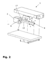
Fig. 1 zeigt eine Laserbearbeitungsmaschine 1 mit einereinzigen Laserschweißoptik 4, welche ausgehend von einer Position in der Mitte der Laserschweißbearbeitungsmaschine 1 (Ruhestellung) nach außen in Richtung der linken oder rechten Seite derLaserschweißbearbeitungsmaschine 1 schweißen kann. An Stelle der einzigen Laserschweißoptik 4 ist es auch denkbar, zwei Laserschweißoptiken einzusetzen, welche jeweils in Richtung der linken bzw. der rechten Seite derLaserschweißbearbeitungsmaschine 1 schweißen können. -
Fig. 2 unterscheidet sichvon Figur 1 durch Ausblenden der Spannbalken, der Laserschweißoptik, der Mittel zur Führung der Laserschweißoptik und einer Kiste, so dass der Auflagebalken 15 sichtbar ist.Auf dem Auflagebalken 15sind Auflageelemente 9 angeordnet, auf denen dieKiste 2 aufliegt und eingespannt werden kann. Zur Berücksichtigung unterschiedlicher Werkstücklängen, Störkonturen und Nahtgeometrien eines zu bearbeitenden Werkstücks können Auflageelemente 9 unterschiedlicher Länge L und unterschiedlicher Anzahl aufdem Auflagebalken 15 positioniert werden (siehe auchFig. 5 :Auflageelemente 9, 9').Die Auflageelemente 9 sind als Winkelprofile ausgebildet,wobei ein Schenkel 16 andem Auflagebalken 15 anliegt und der andereSchenkel 17auf dem Auflagebalken 15 aufliegt. Dadurch können dieAuflageelemente 9 leicht positioniert werden. -
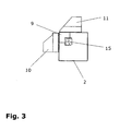
Fig. 3 zeigt das Einspannen beispielhaft anhand derKiste 2 durch das Zusammenwirken des Auflagebalkens 15,der Auflageelemente 9 und der Spannbalken 10und 11.Die Spannbalken 10 und 11 drücken über dieKiste 2 jeweils auf dieAußenseiten der Schenkel 16und 17der Auflageelemente 9. DasEinspannen der Kiste 3 erfolgt analog. -
Fig. 4 verdeutlicht, an welcher Stelle dieKiste 3 geschweißt wird. Die durch Abkanten aus einem Blech entstandeneKiste 3 ist zwischenden Spannbalken 10 und 11 undden Auflageelementen 9 fixiert, so dassein Laserstrahl 18eine Längskante 19der Kiste 3 schweißen kann.
-
Fig. 1 shows alaser processing machine 1 with a singlelaser welding optics 4, which can weld starting from a position in the center of the laser welding machine 1 (rest position) outwards in the direction of the left or right side of thelaser welding machine 1. Instead of the singlelaser welding optics 4, it is also conceivable to use two laser welding optics which can each weld in the direction of the left or the right side of thelaser welding machine 1. -
Fig. 2 differs fromFIG. 1 by hiding the clamping bars, the laser welding optics, the means for guiding the laser welding optics and a box, so that the supportingbeam 15 is visible. On thesupport beam 15support elements 9 are arranged, on which thebox 2 rests and can be clamped. To take account of different workpiece lengths, interference contours and seam geometries of a workpiece to be machined,support elements 9 of different lengths L and different numbers can be positioned on the support beam 15 (see also FIGFig. 5 :Support elements 9, 9 '). Thesupport elements 9 are formed as angle profiles, wherein aleg 16 rests against thesupport beam 15 and theother leg 17 rests on thesupport beam 15. As a result, thesupport elements 9 can be easily positioned. -
Fig. 3 shows the clamping example by way of thebox 2 by the interaction of thesupport beam 15, thesupport elements 9 and the clamping bars 10 and 11. The clamping bars 10 and 11 press on thebox 2 each on the outer sides of thelegs support elements 9. The clamping thebox 3 is analogous. -
Fig. 4 clarifies where thebox 3 is welded. Thebox 3 formed by folding from a sheet metal is fixed between the clamping bars 10 and 11 and the supportingelements 9, so that alaser beam 18 can weld alongitudinal edge 19 of thebox 3.
Wenn nun eine Längskante der Kiste geschweißt wurde, muss die Kiste gedreht werden, um die nächste Längskante zu schweißen. Daher betrifft die Erfindung auch ein Verfahren zum Schweißen der Längskanten von Kisten. Zunächst wird eine Kiste 20 gemäß
- 11
- LaserbearbeitungsmaschineLaser processing machine
- 22
- Kistebox
- 33
- Kistebox
- 44
- LaserschweißoptikLaser welding optics
- 55
- HaubeHood
- 66
- Führungguide
- 77
- Haubenführungcover guide
- 88th
- Doppelpfeildouble arrow
- 99
- Auflageelementsupport element
- 9'9 '
- Auflageelementsupport element
- 1010
- Spannbalkenclamping beams
- 1111
- Spannbalkenclamping beams
- 1212
- Ausnehmungrecess
- 1313
- Randedge
- 1414
- Tischtable
- 1515
- Auflagebalkensupport beam
- 1616
- Schenkelleg
- 1717
- Schenkelleg
- 1818
- Laserstrahllaser beam
- 1919
- Längskantelongitudinal edge
- 2020
- Kistebox
- 2121
- Längskantelongitudinal edge
- 2222
- Erste DrehachseFirst axis of rotation
- 2323
- Längskantelongitudinal edge
- 2424
- Zweite DrehachseSecond axis of rotation
- 2525
- Längskantelongitudinal edge
- 2626
- Längskantelongitudinal edge
- 2727
- Laserstrahllaser beam
- 2828
- Blechzuschnittsheet metal blank
- 2929
- Kistenbodenbox bottom
- 3030
- KistenseitenwandCrate sidewall
- 3131
- Abkantlinieopening line
- 3232
- Schweißrichtungwelding direction
- 3333
- Kisteneckebox corner
- 3434
- Kisteneckebox corner
Claims (7)
- Laser processing machine (1) for producing linear weld seams (19; 21, 23, 25, 26) on a workpiece (2; 3; 20) which is constructed as a box or as a similarly constructed object, comprising:an optical laser welding unit, (4),a workpiece support for the workpiece (2; 3; 20),and clamping means (10, 11) for clamping the workpiece (2; 3; 20) against the workpiece support,characterised in that
the optical laser welding unit (4) is guided in a linearly displaceable manner,
in that the workpiece support is formed in each case by at least one support element (9) on each free bar end of a support bar (15), which support element extends parallel with the displacement direction (8) of the optical laser welding unit (4),
and
in that the clamping means (10, 11) can clamp the workpiece (2; 3; 20), which is pushed from an open workpiece side onto one or the other bar end and onto the at least one support element (9) which is arranged thereon, against the at least one support element (9). - Laser processing machine according to claim 1, characterised in that the clamping means are formed by means of two clamping bars (10, 11).
- Laser processing machine according to either of the preceding claims, characterised in that means for clamping the workpiece (2; 3; 20) in a mirror-symmetrical manner are provided.
- Laser processing machine according to any one of the preceding claims, characterised in that a sensor for establishing the length of the weld seam and means for storing the established data are provided.
- Method for laser welding four longitudinal edges (21, 23, 25, 26) of a workpiece (20), having the following sequence of method steps:i) placing the workpiece (20) from an open workpiece side onto one of the two free bar ends of a support bar (15);ii) clamping the workpiece (20) against at least one support element (9) which is arranged on the bar end;iii) adjusting an optical laser welding unit (4) with respect to angular position and/or spacing with respect to the workpiece (20);iv) welding the first longitudinal edge (21);v) rotating the workpiece (20) through 180° with respect to a first axis of rotation (22) which is defined by the longitudinal centre axis thereof;vi) welding the second longitudinal edge (23);vii) clamping the workpiece (20) again after it has been rotated through 180° with respect to a second axis of rotation (24) which extends perpendicularly relative to the longitudinal centre axis thereof and through the centre of the workpiece (20);viii) welding the third longitudinal edge (25);ix) rotating the workpiece (20) through 180° with respect to the first axis of rotation (22);x) welding the fourth longitudinal edge (26).
- Method according to claim 5, characterised in that the length of the weld seam is established.
- Method according to claim 5 or claim 6, characterised in that the welding operation, starting from an edge (33) which is associated with the workpiece opening, such as, for example, the box opening, and which is opposite a workpiece corner (34) associated with the workpiece base, is carried out in the direction of this workpiece corner (34).
Priority Applications (2)
| Application Number | Priority Date | Filing Date | Title |
|---|---|---|---|
| EP03021262A EP1516693B1 (en) | 2003-09-19 | 2003-09-19 | Laser machining machine for producing linear welding seams and process for producing linear welding seams onto a workpiece |
| US10/943,140 US20050115934A1 (en) | 2003-09-19 | 2004-09-17 | Laser processing for providing linear weld seams |
Applications Claiming Priority (1)
| Application Number | Priority Date | Filing Date | Title |
|---|---|---|---|
| EP03021262A EP1516693B1 (en) | 2003-09-19 | 2003-09-19 | Laser machining machine for producing linear welding seams and process for producing linear welding seams onto a workpiece |
Publications (2)
| Publication Number | Publication Date |
|---|---|
| EP1516693A1 EP1516693A1 (en) | 2005-03-23 |
| EP1516693B1 true EP1516693B1 (en) | 2012-11-07 |
Family
ID=34178446
Family Applications (1)
| Application Number | Title | Priority Date | Filing Date |
|---|---|---|---|
| EP03021262A Expired - Lifetime EP1516693B1 (en) | 2003-09-19 | 2003-09-19 | Laser machining machine for producing linear welding seams and process for producing linear welding seams onto a workpiece |
Country Status (2)
| Country | Link |
|---|---|
| US (1) | US20050115934A1 (en) |
| EP (1) | EP1516693B1 (en) |
Cited By (1)
| Publication number | Priority date | Publication date | Assignee | Title |
|---|---|---|---|---|
| CN104625401A (en) * | 2015-01-21 | 2015-05-20 | 胡和萍 | Bearing fixing seat device for laser welding machine |
Families Citing this family (1)
| Publication number | Priority date | Publication date | Assignee | Title |
|---|---|---|---|---|
| CN116586840B (en) * | 2023-06-02 | 2024-01-16 | 常州市长扬风机有限公司 | Welding device for variable frequency motor housing |
Family Cites Families (43)
| Publication number | Priority date | Publication date | Assignee | Title |
|---|---|---|---|---|
| US3068351A (en) * | 1959-03-27 | 1962-12-11 | American Mach & Foundry | Welding machine |
| US3268381A (en) * | 1963-10-24 | 1966-08-23 | Ishikawa Kazuo | Method of constructing a plastic container |
| US3473001A (en) * | 1967-04-10 | 1969-10-14 | Airline Welding & Eng | Welding machine carriage and track assembly |
| AT305711B (en) * | 1969-06-06 | 1973-03-12 | Voest Ag | Shaped tube |
| US3591757A (en) * | 1970-01-06 | 1971-07-06 | Amf Inc | Welding by high frequency current penetration |
| YU139471A (en) * | 1970-06-11 | 1984-08-31 | Jentsch Hans G | Method of manufcturing bags from multifoil plastics |
| JPS5644187B2 (en) * | 1973-07-18 | 1981-10-17 | ||
| US3991294A (en) * | 1973-11-13 | 1976-11-09 | The Procter & Gamble Company | Apparatus for making longitudinally partitioned tubular bodies and container assemblies |
| US3937914A (en) * | 1974-08-02 | 1976-02-10 | Thermatool Corporation | Method and apparatus for manufacturing welded metal tubes of finite length |
| US3958098A (en) * | 1974-09-03 | 1976-05-18 | Sumitomo Shipbuilding & Machinery Co., Ltd. | Apparatus for automatic and vertical fillet welding |
| FR2338766A1 (en) * | 1976-01-20 | 1977-08-19 | Saurin Emmanuel | METHOD FOR MANUFACTURING A TIN CAN AND DEVICE FOR CARRYING OUT THIS PROCESS |
| US4176269A (en) * | 1976-02-03 | 1979-11-27 | Merrick Welding International, Inc. | Clamping apparatus for welding circumferential articles |
| US4101752A (en) * | 1976-09-15 | 1978-07-18 | Westinghouse Electric Corp. | Process for welding corner cells in fuel assembly grids |
| US4088890A (en) * | 1976-09-28 | 1978-05-09 | United Technologies Corporation | Optical position detector |
| US4301911A (en) * | 1979-07-18 | 1981-11-24 | Pneumatic Scale Corporation | Apparatus for handling a tubular carton blank |
| US4369957A (en) * | 1981-08-03 | 1983-01-25 | Williams Stanley B | Device for clamping and aligning plates to be joined in selected angular relationship |
| JPS5885083A (en) * | 1981-11-13 | 1983-05-21 | 株式会社東芝 | Manufacture of door of refrigerator |
| US4541055A (en) * | 1982-09-01 | 1985-09-10 | Westinghouse Electric Corp. | Laser machining system |
| US4538956A (en) * | 1982-09-01 | 1985-09-03 | Westinghouse Electric Corp. | Workpiece gripping and manipulating apparatus for laser welding systems and the like |
| US4492844A (en) * | 1982-09-01 | 1985-01-08 | Westinghouse Electric Corp. | Welding plates for a fuel rod grid |
| US4500488A (en) * | 1982-09-07 | 1985-02-19 | The United States Of America As Represented By The United States Department Of Energy | Encapsulated fuel unit and method of forming same |
| US4574176A (en) * | 1983-11-28 | 1986-03-04 | Sws Incorporated | Method and apparatus for pulsed high energy density welding |
| JPS62104689A (en) * | 1984-02-29 | 1987-05-15 | エルパトロ−ニク・アクチエンゲゼルシヤフト | Device for laser-welding vertical edge of can cylindrical section |
| US4639574A (en) * | 1984-10-19 | 1987-01-27 | Ductmate Industries, Inc. | Automatic duct welding machine |
| US4745259A (en) * | 1986-07-21 | 1988-05-17 | Russ Wray H | Automatic corner welding adapter |
| DE3630889A1 (en) * | 1986-09-11 | 1988-03-24 | Krupp Gmbh | METHOD FOR THE LENGTH SEW WELDING OF CONTAINER HULLS BY LASER BEAM AND DEVICE FOR CARRYING OUT THE METHOD |
| US4829741A (en) * | 1986-09-12 | 1989-05-16 | Langen Research B.V. | Apparatus for packing and processing a meat product |
| US4977512A (en) * | 1987-02-05 | 1990-12-11 | Shibuya Kogyo Co., Ltd. | Three dimensional simultaneous machining and measuring system |
| US5005801A (en) * | 1989-08-18 | 1991-04-09 | Giarrocco Iii Martin A | Jack hanging apparatus |
| FR2694714B1 (en) * | 1992-08-14 | 1994-11-10 | Lorraine Laminage | Continuous edge-to-edge docking and welding installation of at least two sheet metal blanks using a laser beam. |
| US5533399A (en) * | 1992-09-30 | 1996-07-09 | Wayne State University | Method and apparatus for non-destructive measurement of elastic properties of structural materials |
| US5851248A (en) * | 1992-10-02 | 1998-12-22 | Nordson Corporation | Filter cartridge assembly for powder coating booth and collection system |
| US5385628A (en) * | 1993-03-24 | 1995-01-31 | Davis; Roland | Gasket welding apparatus and method |
| US5494553A (en) * | 1993-09-20 | 1996-02-27 | Colucci; William G. | Multi-purpose clamping apparatus |
| US5500503A (en) * | 1994-08-04 | 1996-03-19 | Midwest Research Institute | Simultaneous laser cutting and welding of metal foil to edge of a plate |
| US5674420A (en) * | 1995-06-12 | 1997-10-07 | Worthington Industries Incorporated | Clamping device for welding machine |
| US5772233A (en) * | 1996-04-09 | 1998-06-30 | Decoma International Inc. | Expandable painting wagon |
| EP0803313A3 (en) * | 1996-04-23 | 2000-01-12 | Daido Tokushuko Kabushiki Kaisha | Method and apparatus for diffusion bonding |
| US6080961A (en) * | 1996-10-31 | 2000-06-27 | Nissan Motor Co., Ltd. | Blank material positioning device and blank material positioning method |
| US6024024A (en) * | 1998-04-02 | 2000-02-15 | Favaretto; Paolo | Table structure |
| US6079187A (en) * | 1998-12-01 | 2000-06-27 | Hart & Cooley, Inc. | Apparatus for packaging flexible duct for shipment and method for performing the same |
| CA2384155C (en) * | 1999-09-10 | 2006-11-21 | Amweld Building Products, Llc | Door construction and method |
| WO2003064115A1 (en) * | 2002-01-30 | 2003-08-07 | Wolfcraft Gmbh | Folding cross-cut saw stand |
-
2003
- 2003-09-19 EP EP03021262A patent/EP1516693B1/en not_active Expired - Lifetime
-
2004
- 2004-09-17 US US10/943,140 patent/US20050115934A1/en not_active Abandoned
Cited By (1)
| Publication number | Priority date | Publication date | Assignee | Title |
|---|---|---|---|---|
| CN104625401A (en) * | 2015-01-21 | 2015-05-20 | 胡和萍 | Bearing fixing seat device for laser welding machine |
Also Published As
| Publication number | Publication date |
|---|---|
| EP1516693A1 (en) | 2005-03-23 |
| US20050115934A1 (en) | 2005-06-02 |
Similar Documents
| Publication | Publication Date | Title |
|---|---|---|
| EP3391987B1 (en) | Method for welding sheet metal sections | |
| EP1838492B1 (en) | Installation for producing and method for assembling parts | |
| EP2377639B1 (en) | Machine for laser processing either flat or cylindrical workpieces ; Method of customising such machine | |
| DE4431384A1 (en) | Device for framing vehicle bodies | |
| AT523568B1 (en) | bending machine | |
| EP2285522A1 (en) | Laser machining tool having expanded work space | |
| EP3528996B1 (en) | Method for predicting the tilt inclination of a workpiece part being cut free, and machine tool for machining a planar workpiece | |
| DE19853366B4 (en) | Apparatus and method for forming | |
| EP4408605B1 (en) | Device and method for laser welding steel plates | |
| EP3515618B1 (en) | Tool and machine tool and method for machining planar workpieces | |
| WO2018055193A1 (en) | Tool, machine tool, and method for machining planar workpieces | |
| WO2018091536A1 (en) | Laser pressure welding | |
| DE10135233A1 (en) | Circular machine for provision of fracture separation points in components, e.g. for production of connecting rods, has stationary inner work station and outer work stations in circulating section | |
| EP3302840B1 (en) | Production system for producing workpieces from sheet metal and method therefor | |
| EP1516693B1 (en) | Laser machining machine for producing linear welding seams and process for producing linear welding seams onto a workpiece | |
| EP3746288B1 (en) | Apparatus for joining, in particular laser welding, two components, and operating method for such a joining apparatus | |
| WO2018055183A1 (en) | Tool, machine tool, and method for machining planar workpieces | |
| EP1346792A1 (en) | Welding unit | |
| EP1128929A1 (en) | Method and device for producing welded blanks | |
| EP0743135A2 (en) | Process for bonding two workpieces | |
| DE102018105661A1 (en) | TRANSPORT SYSTEM | |
| DE10029293A1 (en) | Laser beam welding device for diverse sheet material plates has supporting frame and clamping devices with modular set of identical, serially connectable basic and clamping modules | |
| EP3331685B1 (en) | Mounting device | |
| DE3536015A1 (en) | Manufacturing station, in particular for motor vehicle bodies | |
| AT514788B1 (en) | Bending tool from several tool elements |
Legal Events
| Date | Code | Title | Description |
|---|---|---|---|
| PUAI | Public reference made under article 153(3) epc to a published international application that has entered the european phase |
Free format text: ORIGINAL CODE: 0009012 |
|
| AK | Designated contracting states |
Kind code of ref document: A1 Designated state(s): AT BE BG CH CY CZ DE DK EE ES FI FR GB GR HU IE IT LI LU MC NL PT RO SE SI SK TR |
|
| AX | Request for extension of the european patent |
Extension state: AL LT LV MK |
|
| 17P | Request for examination filed |
Effective date: 20050831 |
|
| AKX | Designation fees paid |
Designated state(s): AT BE BG CH CY CZ DE DK EE ES FI FR GB GR HU IE IT LI LU MC NL PT RO SE SI SK TR |
|
| GRAP | Despatch of communication of intention to grant a patent |
Free format text: ORIGINAL CODE: EPIDOSNIGR1 |
|
| GRAS | Grant fee paid |
Free format text: ORIGINAL CODE: EPIDOSNIGR3 |
|
| GRAA | (expected) grant |
Free format text: ORIGINAL CODE: 0009210 |
|
| AK | Designated contracting states |
Kind code of ref document: B1 Designated state(s): AT BE BG CH CY CZ DE DK EE ES FI FR GB GR HU IE IT LI LU MC NL PT RO SE SI SK TR |
|
| REG | Reference to a national code |
Ref country code: GB Ref legal event code: FG4D Free format text: NOT ENGLISH |
|
| REG | Reference to a national code |
Ref country code: CH Ref legal event code: EP Ref country code: AT Ref legal event code: REF Ref document number: 582784 Country of ref document: AT Kind code of ref document: T Effective date: 20121115 |
|
| REG | Reference to a national code |
Ref country code: IE Ref legal event code: FG4D Free format text: LANGUAGE OF EP DOCUMENT: GERMAN |
|
| REG | Reference to a national code |
Ref country code: DE Ref legal event code: R096 Ref document number: 50314575 Country of ref document: DE Effective date: 20130103 |
|
| REG | Reference to a national code |
Ref country code: NL Ref legal event code: VDEP Effective date: 20121107 |
|
| PG25 | Lapsed in a contracting state [announced via postgrant information from national office to epo] |
Ref country code: SE Free format text: LAPSE BECAUSE OF FAILURE TO SUBMIT A TRANSLATION OF THE DESCRIPTION OR TO PAY THE FEE WITHIN THE PRESCRIBED TIME-LIMIT Effective date: 20121107 Ref country code: NL Free format text: LAPSE BECAUSE OF FAILURE TO SUBMIT A TRANSLATION OF THE DESCRIPTION OR TO PAY THE FEE WITHIN THE PRESCRIBED TIME-LIMIT Effective date: 20121107 Ref country code: ES Free format text: LAPSE BECAUSE OF FAILURE TO SUBMIT A TRANSLATION OF THE DESCRIPTION OR TO PAY THE FEE WITHIN THE PRESCRIBED TIME-LIMIT Effective date: 20130218 Ref country code: FI Free format text: LAPSE BECAUSE OF FAILURE TO SUBMIT A TRANSLATION OF THE DESCRIPTION OR TO PAY THE FEE WITHIN THE PRESCRIBED TIME-LIMIT Effective date: 20121107 |
|
| PG25 | Lapsed in a contracting state [announced via postgrant information from national office to epo] |
Ref country code: CY Free format text: LAPSE BECAUSE OF FAILURE TO SUBMIT A TRANSLATION OF THE DESCRIPTION OR TO PAY THE FEE WITHIN THE PRESCRIBED TIME-LIMIT Effective date: 20121107 Ref country code: SI Free format text: LAPSE BECAUSE OF FAILURE TO SUBMIT A TRANSLATION OF THE DESCRIPTION OR TO PAY THE FEE WITHIN THE PRESCRIBED TIME-LIMIT Effective date: 20121107 Ref country code: PT Free format text: LAPSE BECAUSE OF FAILURE TO SUBMIT A TRANSLATION OF THE DESCRIPTION OR TO PAY THE FEE WITHIN THE PRESCRIBED TIME-LIMIT Effective date: 20130307 Ref country code: GR Free format text: LAPSE BECAUSE OF FAILURE TO SUBMIT A TRANSLATION OF THE DESCRIPTION OR TO PAY THE FEE WITHIN THE PRESCRIBED TIME-LIMIT Effective date: 20130208 |
|
| PG25 | Lapsed in a contracting state [announced via postgrant information from national office to epo] |
Ref country code: SK Free format text: LAPSE BECAUSE OF FAILURE TO SUBMIT A TRANSLATION OF THE DESCRIPTION OR TO PAY THE FEE WITHIN THE PRESCRIBED TIME-LIMIT Effective date: 20121107 Ref country code: DK Free format text: LAPSE BECAUSE OF FAILURE TO SUBMIT A TRANSLATION OF THE DESCRIPTION OR TO PAY THE FEE WITHIN THE PRESCRIBED TIME-LIMIT Effective date: 20121107 Ref country code: EE Free format text: LAPSE BECAUSE OF FAILURE TO SUBMIT A TRANSLATION OF THE DESCRIPTION OR TO PAY THE FEE WITHIN THE PRESCRIBED TIME-LIMIT Effective date: 20121107 Ref country code: BG Free format text: LAPSE BECAUSE OF FAILURE TO SUBMIT A TRANSLATION OF THE DESCRIPTION OR TO PAY THE FEE WITHIN THE PRESCRIBED TIME-LIMIT Effective date: 20130207 Ref country code: CZ Free format text: LAPSE BECAUSE OF FAILURE TO SUBMIT A TRANSLATION OF THE DESCRIPTION OR TO PAY THE FEE WITHIN THE PRESCRIBED TIME-LIMIT Effective date: 20121107 |
|
| PG25 | Lapsed in a contracting state [announced via postgrant information from national office to epo] |
Ref country code: RO Free format text: LAPSE BECAUSE OF FAILURE TO SUBMIT A TRANSLATION OF THE DESCRIPTION OR TO PAY THE FEE WITHIN THE PRESCRIBED TIME-LIMIT Effective date: 20121107 |
|
| PLBE | No opposition filed within time limit |
Free format text: ORIGINAL CODE: 0009261 |
|
| STAA | Information on the status of an ep patent application or granted ep patent |
Free format text: STATUS: NO OPPOSITION FILED WITHIN TIME LIMIT |
|
| 26N | No opposition filed |
Effective date: 20130808 |
|
| REG | Reference to a national code |
Ref country code: DE Ref legal event code: R097 Ref document number: 50314575 Country of ref document: DE Effective date: 20130808 |
|
| BERE | Be: lapsed |
Owner name: TRUMPF LASER- UND SYSTEMTECHNIK G.M.B.H. Effective date: 20130930 |
|
| PG25 | Lapsed in a contracting state [announced via postgrant information from national office to epo] |
Ref country code: MC Free format text: LAPSE BECAUSE OF FAILURE TO SUBMIT A TRANSLATION OF THE DESCRIPTION OR TO PAY THE FEE WITHIN THE PRESCRIBED TIME-LIMIT Effective date: 20121107 |
|
| REG | Reference to a national code |
Ref country code: CH Ref legal event code: PL |
|
| GBPC | Gb: european patent ceased through non-payment of renewal fee |
Effective date: 20130919 |
|
| REG | Reference to a national code |
Ref country code: IE Ref legal event code: MM4A |
|
| PG25 | Lapsed in a contracting state [announced via postgrant information from national office to epo] |
Ref country code: IE Free format text: LAPSE BECAUSE OF NON-PAYMENT OF DUE FEES Effective date: 20130919 Ref country code: CH Free format text: LAPSE BECAUSE OF NON-PAYMENT OF DUE FEES Effective date: 20130930 Ref country code: LI Free format text: LAPSE BECAUSE OF NON-PAYMENT OF DUE FEES Effective date: 20130930 Ref country code: GB Free format text: LAPSE BECAUSE OF NON-PAYMENT OF DUE FEES Effective date: 20130919 Ref country code: BE Free format text: LAPSE BECAUSE OF NON-PAYMENT OF DUE FEES Effective date: 20130930 |
|
| REG | Reference to a national code |
Ref country code: AT Ref legal event code: MM01 Ref document number: 582784 Country of ref document: AT Kind code of ref document: T Effective date: 20130919 |
|
| PG25 | Lapsed in a contracting state [announced via postgrant information from national office to epo] |
Ref country code: AT Free format text: LAPSE BECAUSE OF NON-PAYMENT OF DUE FEES Effective date: 20130919 |
|
| PG25 | Lapsed in a contracting state [announced via postgrant information from national office to epo] |
Ref country code: TR Free format text: LAPSE BECAUSE OF FAILURE TO SUBMIT A TRANSLATION OF THE DESCRIPTION OR TO PAY THE FEE WITHIN THE PRESCRIBED TIME-LIMIT Effective date: 20121107 |
|
| PG25 | Lapsed in a contracting state [announced via postgrant information from national office to epo] |
Ref country code: LU Free format text: LAPSE BECAUSE OF NON-PAYMENT OF DUE FEES Effective date: 20130919 Ref country code: HU Free format text: LAPSE BECAUSE OF FAILURE TO SUBMIT A TRANSLATION OF THE DESCRIPTION OR TO PAY THE FEE WITHIN THE PRESCRIBED TIME-LIMIT; INVALID AB INITIO Effective date: 20030919 |
|
| REG | Reference to a national code |
Ref country code: FR Ref legal event code: PLFP Year of fee payment: 14 |
|
| REG | Reference to a national code |
Ref country code: FR Ref legal event code: PLFP Year of fee payment: 15 |
|
| REG | Reference to a national code |
Ref country code: FR Ref legal event code: PLFP Year of fee payment: 16 |
|
| PGFP | Annual fee paid to national office [announced via postgrant information from national office to epo] |
Ref country code: IT Payment date: 20210922 Year of fee payment: 19 Ref country code: FR Payment date: 20210921 Year of fee payment: 19 |
|
| PGFP | Annual fee paid to national office [announced via postgrant information from national office to epo] |
Ref country code: DE Payment date: 20210920 Year of fee payment: 19 |
|
| REG | Reference to a national code |
Ref country code: DE Ref legal event code: R119 Ref document number: 50314575 Country of ref document: DE |
|
| PG25 | Lapsed in a contracting state [announced via postgrant information from national office to epo] |
Ref country code: FR Free format text: LAPSE BECAUSE OF NON-PAYMENT OF DUE FEES Effective date: 20220930 Ref country code: DE Free format text: LAPSE BECAUSE OF NON-PAYMENT OF DUE FEES Effective date: 20230401 |
|
| PG25 | Lapsed in a contracting state [announced via postgrant information from national office to epo] |
Ref country code: IT Free format text: LAPSE BECAUSE OF NON-PAYMENT OF DUE FEES Effective date: 20220919 |