EP1516632A1 - Verfahren und Vorrichtung zur Dampfsterilisation - Google Patents
Verfahren und Vorrichtung zur Dampfsterilisation Download PDFInfo
- Publication number
- EP1516632A1 EP1516632A1 EP04255580A EP04255580A EP1516632A1 EP 1516632 A1 EP1516632 A1 EP 1516632A1 EP 04255580 A EP04255580 A EP 04255580A EP 04255580 A EP04255580 A EP 04255580A EP 1516632 A1 EP1516632 A1 EP 1516632A1
- Authority
- EP
- European Patent Office
- Prior art keywords
- cup
- steam
- temperature sensor
- stainless steel
- assembly
- Prior art date
- Legal status (The legal status is an assumption and is not a legal conclusion. Google has not performed a legal analysis and makes no representation as to the accuracy of the status listed.)
- Withdrawn
Links
Images
Classifications
-
- F—MECHANICAL ENGINEERING; LIGHTING; HEATING; WEAPONS; BLASTING
- F22—STEAM GENERATION
- F22B—METHODS OF STEAM GENERATION; STEAM BOILERS
- F22B1/00—Methods of steam generation characterised by form of heating method
- F22B1/28—Methods of steam generation characterised by form of heating method in boilers heated electrically
- F22B1/287—Methods of steam generation characterised by form of heating method in boilers heated electrically with water in sprays or in films
-
- A—HUMAN NECESSITIES
- A61—MEDICAL OR VETERINARY SCIENCE; HYGIENE
- A61L—METHODS OR APPARATUS FOR STERILISING MATERIALS OR OBJECTS IN GENERAL; DISINFECTION, STERILISATION OR DEODORISATION OF AIR; CHEMICAL ASPECTS OF BANDAGES, DRESSINGS, ABSORBENT PADS OR SURGICAL ARTICLES; MATERIALS FOR BANDAGES, DRESSINGS, ABSORBENT PADS OR SURGICAL ARTICLES
- A61L2/00—Disinfection or sterilisation of materials or objects, in general; Accessories therefor
- A61L2/02—Disinfection or sterilisation of materials or objects, in general; Accessories therefor using physical processes
- A61L2/04—Heat
- A61L2/06—Hot gas
- A61L2/07—Steam
-
- A—HUMAN NECESSITIES
- A61—MEDICAL OR VETERINARY SCIENCE; HYGIENE
- A61L—METHODS OR APPARATUS FOR STERILISING MATERIALS OR OBJECTS IN GENERAL; DISINFECTION, STERILISATION OR DEODORISATION OF AIR; CHEMICAL ASPECTS OF BANDAGES, DRESSINGS, ABSORBENT PADS OR SURGICAL ARTICLES; MATERIALS FOR BANDAGES, DRESSINGS, ABSORBENT PADS OR SURGICAL ARTICLES
- A61L2/00—Disinfection or sterilisation of materials or objects, in general; Accessories therefor
- A61L2/26—Accessories
-
- A—HUMAN NECESSITIES
- A61—MEDICAL OR VETERINARY SCIENCE; HYGIENE
- A61L—METHODS OR APPARATUS FOR STERILISING MATERIALS OR OBJECTS IN GENERAL; DISINFECTION, STERILISATION OR DEODORISATION OF AIR; CHEMICAL ASPECTS OF BANDAGES, DRESSINGS, ABSORBENT PADS OR SURGICAL ARTICLES; MATERIALS FOR BANDAGES, DRESSINGS, ABSORBENT PADS OR SURGICAL ARTICLES
- A61L2103/00—Materials or objects being the target of disinfection or sterilisation
- A61L2103/15—Laboratory, medical or dentistry appliances, e.g. catheters or sharps
-
- A—HUMAN NECESSITIES
- A61—MEDICAL OR VETERINARY SCIENCE; HYGIENE
- A61L—METHODS OR APPARATUS FOR STERILISING MATERIALS OR OBJECTS IN GENERAL; DISINFECTION, STERILISATION OR DEODORISATION OF AIR; CHEMICAL ASPECTS OF BANDAGES, DRESSINGS, ABSORBENT PADS OR SURGICAL ARTICLES; MATERIALS FOR BANDAGES, DRESSINGS, ABSORBENT PADS OR SURGICAL ARTICLES
- A61L2202/00—Aspects relating to methods or apparatus for disinfecting or sterilising materials or objects
- A61L2202/10—Apparatus features
- A61L2202/11—Apparatus for generating biocidal substances, e.g. vaporisers, UV lamps
-
- A—HUMAN NECESSITIES
- A61—MEDICAL OR VETERINARY SCIENCE; HYGIENE
- A61L—METHODS OR APPARATUS FOR STERILISING MATERIALS OR OBJECTS IN GENERAL; DISINFECTION, STERILISATION OR DEODORISATION OF AIR; CHEMICAL ASPECTS OF BANDAGES, DRESSINGS, ABSORBENT PADS OR SURGICAL ARTICLES; MATERIALS FOR BANDAGES, DRESSINGS, ABSORBENT PADS OR SURGICAL ARTICLES
- A61L2202/00—Aspects relating to methods or apparatus for disinfecting or sterilising materials or objects
- A61L2202/10—Apparatus features
- A61L2202/14—Means for controlling sterilisation processes, data processing, presentation and storage means, e.g. sensors, controllers, programs
-
- A—HUMAN NECESSITIES
- A61—MEDICAL OR VETERINARY SCIENCE; HYGIENE
- A61L—METHODS OR APPARATUS FOR STERILISING MATERIALS OR OBJECTS IN GENERAL; DISINFECTION, STERILISATION OR DEODORISATION OF AIR; CHEMICAL ASPECTS OF BANDAGES, DRESSINGS, ABSORBENT PADS OR SURGICAL ARTICLES; MATERIALS FOR BANDAGES, DRESSINGS, ABSORBENT PADS OR SURGICAL ARTICLES
- A61L2202/00—Aspects relating to methods or apparatus for disinfecting or sterilising materials or objects
- A61L2202/10—Apparatus features
- A61L2202/15—Biocide distribution means, e.g. nozzles, pumps, manifolds, fans, baffles, sprayers
Definitions
- the present invention is directed to a method and apparatus for the steam sterilization of articles, and in particular to a method and apparatus employing a stainless steel steam generator with a brazed thermocouple and spray nozzle combination for improved steam-on-demand generation.
- the boilers are made of aluminum, which is cast around its heating coils.
- the aluminum material tends to oxidize over time.
- the oxides can coat the temperature sensor and affect its performance.
- steam generation output is sensitive to the manner in which the water is injected into the boiler chamber and placement of the temperature sensor, and steam output can sometimes suffer due to improper water injection and sensor placement.
- the present invention provides an improved steam-on-demand generator that has improved corrosion resistance, and better steam generation capability.
- Another object of the invention is a steam-on-demand generator having a stainless steel chamber and brazed construction.
- One other object of the invention is a method of generating steam on demand using the inventive steam generator.
- the invention is an improvement in the steam-on-demand generators of the prior art, particularly those disclosed in the aforementioned Newman patents.
- the invention relates to a steam on demand generator that has a cup assembly, a heating device for heating the cup assembly and an interior thereof, a water injection device for supplying water to the cup assembly, a steam outlet, and a temperature sensor positioned within the cup assembly. Water is supplied in quantities so that the interior of the cup assembly remains essentially dry during steam generation.
- the invention is an improvement over these types of steam generators in that the cup assembly includes a thin-walled stainless steel cup and stainless steel cap forming the interior. A hollow cone spray nozzle in the stainless steel cap is provided for supplying water to the cup.
- the heating device and a temperature sensitive portion of the temperature sensor are brazed to the stainless steel cup.
- An end portion of the temperature sensor is preferably brazed at a location on an inside wall of the stainless steel cup, the inside wall receiving spray from the hollow cone spray nozzle.
- the temperature sensor can be a thermocouple and at least a side of a tip of the thermocouple should directly contact the inside wall via the brazing, with an end surface or face of the sensor remaining exposed after brazing.
- the cup of the steam generator is configured with a wall portion that both receives the spray from the nozzle and serves as an attachment point for the temperature sensor.
- the heating device can be a heating coil that surrounds a lower portion of the cup assembly, with the lower portion including the wall of the cup.
- the cup can also include a stainless steel stud that is brazed to a bottom of the cup, the stud providing a channel for the temperature sensor to enter the interior.
- the temperature sensor can be brazed to portion of the stud.
- Another aspect of the invention is an improvement in the method of steam-on-demand generation.
- water is dispensed into a cup of the steam generator in pulses to generate steam on demand while maintaining the steam generator essentially dry during steam generation.
- the injection of water is controlled by sensing a temperature of an interior of the steam generator and the cup.
- the invention improves upon this method by dispensing the water in a hollow cone spray pattern with the cone of atomized water contacting a wall of the stainless steel cup, and sensing the interior temperature and temperature of the cup using a temperature sensor placed on a portion of the upstanding wall receiving the dispensed water.
- the temperature sensor can be a thermocouple and an end portion of the temperature sensor can be brazed to the wall with an end face of the end portion exposed after brazing.
- Control over steam generation can utilize a change of temperature sensed by the temperature sensor over time rather than just monitoring the change of temperature as has been done in prior art steam-on-demand generators.
- Another aspect of the invention entails the cup and cap assembly for a steam generator.
- This assembly includes a cap having an opening for water dispensing, a cup, a clamp assembly securing the cap to the cup to form a sealed interior, a heating element brazed to the cup; and a temperature sensor. An end portion of the temperature sensor is positioned in the interior and brazed to a portion of a wall of the cup.
- At least the cap, the cup, the spray nozzle, and clamp assembly are stainless steel.
- the present invention offers significant improvements in the generation of steam on demand for various applications, including sterilization of articles. While the inventive steam generator is preferably used to provide steam on demand for sterilization purposes, it can be used in other applications where steam is required.
- the inventive generator overcomes many of the problems in prior art steam generators related to the presence of aluminum oxides that adversely affect temperature control.
- Use of a stainless steel construction for the steam generator components eliminates the problem with aluminum oxides. It also allows the use of thin walls for the steam generator, thus improving manufacturing costs, and enhancing heat conduction from the heating coils disposed on the outside of the thin walls.
- the invention also solves the problem of attaching thermocouples or other temperature sensors to stainless steel materials through the use of brazing as the attachment mode.
- the inventive steam generator offers superior steam generation as well due to the use of a hollow cone spray nozzle, which directs the injected water in a cone pattern that strikes the hottest part of the boiler. Placement of the temperature sensor in this zone allows for precise control of steam generation.
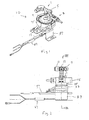
- the steam generator 10 includes a steam outlet assembly 1, an air inlet assembly 3, and a water inlet assembly 5.
- the steam outlet assembly 1 includes tee fitting 7, elbow 9, and pressure relief valve 11.
- the water inlet assembly 5 includes spray nozzle 13, seal 15, nozzle adapter 17, and compression nut 21.
- the air inlet assembly 3 includes elbow compression fitting 23, check valve 25, and hose barb fitting 27. While it is preferred to have these components for outlet of steam, inlet of air, and inlet of water, other arrangements as would be within the skill of the art could be employed for these purposes.
- the steam outlet assembly 1 provides an outlet for steam to exit the generator 10 and be directed via a conduit (not shown) to a sterilizing cassette or other steam-requiring device.
- the air inlet assembly 3 allows air to enter the generator 10 for drying purposes once the steam is no longer in demand, and for other reasons as would be mandated by the particular use of the steam generator. Air supplied by a source (not shown) enters the hose barb 27, through check valve 25, and elbow 23, passes into the generator and exits via the steam outlet assembly 1.
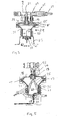
- the generator 10 has a base half assembly 29 and a cap half assembly 31.
- the base half assembly 29 is made up of heating element 33, cup 35, bracket 37, and mounting stud 39 (see Figure 3).
- the base half elements are attached together to form a unitary assembly, and are preferably attached together by brazing.
- the brazing material is a copper based alloy but other materials can be used.
- the components of the base half assembly 29 are made of stainless steel, with the cup having a generally thin wall construction, e.g., wall thickness less than 1.52 mm, to minimize the heating load on the heating element.
- the heating element 33 is shown as a heating coil, but virtually any type of heating device compatible with the base half assembly 29 can be brazed or otherwise made part of the steam generator.
- the cap half assembly 31 is made up of the cap 41, the nozzle adapter 17, and tubes 19.
- the tubes 19 connect to the elbow 23 and tee fitting 7, respectively, to allow egress of steam and ingress of air, respectively, to a chamber formed by the base and cap half assemblies 29 and 31.
- the components of the cap half assembly 31 are also preferably brazed together to form a unitary structure, with a preferred brazing alloy being a nickel-based alloy. Of course, other brazing alloys can be used in this application.
- the base half assembly 29 and cap half assembly 31 are clamped together using a v-band stainless steel coupling 45 and silicone gasket 47.
- the gasket 47 assures a leak free seal between the cap 41 and cup 35 that form the steam generating chamber.
- the steam generator 10 has two safety features, the pressure relief valve 11 noted above, and a thermal fuse 59.
- the fuse 59 is held in place using clamp 61, spring washer 63 and nut 65.
- the steam generator 10 also includes a thermocouple 67, but any temperature sensor could be used that would provide the proper control over the generation of steam.
- the thermocouple 67 extends through the mounting stud 39, along a bottom of the cup 35, and along an upstanding wall 71 of the cup 35, with an end portion 69 terminating at tip surface 79.
- thermocouple end portion 69 is brazed to the wall 71 under conditions, which are designed to maximize performance of the steam generator 10. More specifically, it is preferred to have the end portion 69 in a location that optimizes steam generation. If the thermocouple is improperly situated, then steam generation is compromised.
- thermocouple 67 is brazed in place on the wall 71 at the most thermally sensitive region. It is also preferred to form a brazed joint where the thermocouple meets an end portion 82 of the stud 39, see Figure 5.
- the thermally sensitive region is where: (a) the thermocouple end portion 69 will experience the most rapid increase in temperature in the absence of water, and (b) experience the earliest decrease in temperature in the presence of water. In order to achieve item (a), the end portion 69 should be mounted at the hottest spot on the cup 35. Item (b) suggests that the thermocouple be mounted at the location where the largest amount of atomized water will hit during water spraying.
- brazing alloy used to attach the end 69 to the wall 71. Too much brazing alloy will adversely affect the control of the operation using the thermocouple. To little alloy will not provide the attachment to the wall to sense the wall temperature.
- thermocouple end portion 69 When brazing the thermocouple, it is preferred to have the thermocouple end portion 69, including the very tip portion of the end 69 in contact with the wall 71 of the cup 35.
- the top surface or end face 79, see Figure 3, should be exposed and not covered by brazing material.
- the brazed fillet should be no more than half of the diameter of the thermocouple in size.
- a preferred length of the fillet along the wall 71 is about half of the wall height, the fillet beginning at the face 79 and extending toward a bottom of the cup 35.
- thermocouple The control of the operation of the generator using the thermocouple can follow the method disclosed in the Newmwan patents noted above.
- this prior art method the increase in the temperature of the steam generator was monitored to determine when additional water had to be injected into the steam generator.
- this method did not adequately address runaway conditions, e.g., where the rise in temperature occurred very rapidly.
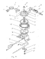
- the tubular heating coils 33 are energized to rapidly heat the thin-walled stainless steel cup 35.
- the rapid heat-up of the cup 35 reduces re-condensation of steam inside the generator 10.
- Water is then supplied via a pump or other device (not shown) to the water inlet assembly 5.
- a pump or other device Prior to water entering the bore 74 of the nozzle 13, it travels through bore 72 in the adaptor 17.
- Water exiting the nozzle is dispersed in a hollow conical pattern 75 and atomized into small droplets that are directed towards the previously-heated upstanding wall 71 and thermocouple end 69. Atomizing the water increases the contact surfaces between the water and the wall 71 to allow for rapid steam generation.
- the wall 71 is shown as upstanding, the steam generator could have other configurations in use, whereby the dispensing of the hollow cone of water may occur horizontally rather than vertically.
- the wall 71 adjacent the heating element 33 and the thermocouple end 69 should receive the hollow cone spray pattern 75 from the nozzle 13.
- the generator is made primarily of stainless steel.
- the cup 35, mounting stud 39, washer 63, cap 41, bracket 37, and clamp 45 are made of stainless steel, preferably an austenitic type such as 304.
- the fitting components for the steam outlet, water inlet and air inlet assemblies are preferably made of brass.
- the nozzle adapter 17 and tubes 19 are preferably made of stainless steel.
Landscapes
- Health & Medical Sciences (AREA)
- Life Sciences & Earth Sciences (AREA)
- Engineering & Computer Science (AREA)
- Veterinary Medicine (AREA)
- General Health & Medical Sciences (AREA)
- Public Health (AREA)
- Animal Behavior & Ethology (AREA)
- Epidemiology (AREA)
- Sustainable Development (AREA)
- Sustainable Energy (AREA)
- Physics & Mathematics (AREA)
- Thermal Sciences (AREA)
- Mechanical Engineering (AREA)
- General Engineering & Computer Science (AREA)
- Apparatus For Disinfection Or Sterilisation (AREA)
Applications Claiming Priority (2)
| Application Number | Priority Date | Filing Date | Title |
|---|---|---|---|
| US10/662,404 US7476369B2 (en) | 2003-09-16 | 2003-09-16 | Apparatus for steam sterilization of articles |
| US662404 | 2003-09-16 |
Publications (1)
| Publication Number | Publication Date |
|---|---|
| EP1516632A1 true EP1516632A1 (de) | 2005-03-23 |
Family
ID=34194711
Family Applications (1)
| Application Number | Title | Priority Date | Filing Date |
|---|---|---|---|
| EP04255580A Withdrawn EP1516632A1 (de) | 2003-09-16 | 2004-09-15 | Verfahren und Vorrichtung zur Dampfsterilisation |
Country Status (7)
| Country | Link |
|---|---|
| US (1) | US7476369B2 (de) |
| EP (1) | EP1516632A1 (de) |
| JP (1) | JP2005121354A (de) |
| KR (1) | KR100642009B1 (de) |
| CN (1) | CN1286532C (de) |
| AU (1) | AU2004212534B2 (de) |
| CA (1) | CA2481635C (de) |
Cited By (2)
| Publication number | Priority date | Publication date | Assignee | Title |
|---|---|---|---|---|
| WO2007027067A1 (en) * | 2005-09-01 | 2007-03-08 | Aqua Doctor Co., Ltd | Sterilizing apparatus and method using high pressure steam |
| EP4541382A1 (de) | 2023-10-16 | 2025-04-23 | MELAG Medizintechnik GmbH & Co. KG | Verfahren zur dampfsterilisation in einem autoklav sowie autoklav |
Families Citing this family (23)
| Publication number | Priority date | Publication date | Assignee | Title |
|---|---|---|---|---|
| US20070042628A1 (en) * | 2005-08-17 | 2007-02-22 | Daniel Lyon | Sanitary, live loaded, pass through fitting apparatus |
| US20070283728A1 (en) * | 2006-06-09 | 2007-12-13 | Nyik Siong Wong | Prevention of scale and sludge in a steam generator of a fabric treatment appliance |
| US20080005923A1 (en) * | 2006-07-07 | 2008-01-10 | Arthur Zwingenberger | Apparatus and method for drying instruments using superheated steam |
| US20080040869A1 (en) * | 2006-08-15 | 2008-02-21 | Nyik Siong Wong | Determining Fabric Temperature in a Fabric Treating Appliance |
| KR100778358B1 (ko) * | 2006-10-16 | 2007-11-29 | 이수호 | 스팀살균장치 |
| US20080092928A1 (en) * | 2006-10-19 | 2008-04-24 | Whirlpool Corporation | Method and Apparatus for Treating Biofilm in an Appliance |
| US20080095660A1 (en) * | 2006-10-19 | 2008-04-24 | Nyik Siong Wong | Method for treating biofilm in an appliance |
| US8393183B2 (en) * | 2007-05-07 | 2013-03-12 | Whirlpool Corporation | Fabric treatment appliance control panel and associated steam operations |
| KR200445369Y1 (ko) * | 2007-07-30 | 2009-07-22 | 정원하 | 주방전용다기능스팀기 |
| US7966683B2 (en) * | 2007-08-31 | 2011-06-28 | Whirlpool Corporation | Method for operating a steam generator in a fabric treatment appliance |
| US8037565B2 (en) * | 2007-08-31 | 2011-10-18 | Whirlpool Corporation | Method for detecting abnormality in a fabric treatment appliance having a steam generator |
| US8555675B2 (en) * | 2007-08-31 | 2013-10-15 | Whirlpool Corporation | Fabric treatment appliance with steam backflow device |
| US8555676B2 (en) | 2007-08-31 | 2013-10-15 | Whirlpool Corporation | Fabric treatment appliance with steam backflow device |
| GB201017461D0 (en) * | 2010-10-15 | 2010-12-01 | Strix Ltd | Electric steam generation |
| US10760853B1 (en) * | 2012-03-15 | 2020-09-01 | Crosstex International, Inc. | Automated thermal exchange system for autoclave sterilizer |
| US8815174B2 (en) | 2012-08-17 | 2014-08-26 | American Sterilizer Company | Steam sterilizer |
| WO2015072509A1 (ja) * | 2013-11-15 | 2015-05-21 | 四国計測工業株式会社 | 高効率熱交換器および高効率熱交換方法 |
| CN104896454A (zh) * | 2015-06-08 | 2015-09-09 | 莱克电气股份有限公司 | 一种用于蒸汽拖把的加热装置 |
| US12565631B2 (en) * | 2021-09-08 | 2026-03-03 | Simple Solutions Distributing, LLC | Brewery and steam vent odor control system |
| CN115227852B (zh) * | 2022-06-06 | 2023-12-15 | 青岛海尔生物医疗股份有限公司 | 消毒机 |
| CN115137858A (zh) * | 2022-06-06 | 2022-10-04 | 青岛海尔生物医疗股份有限公司 | 用于控制消毒机的方法及装置、消毒机、存储介质 |
| CN114984272A (zh) * | 2022-06-06 | 2022-09-02 | 青岛海尔生物医疗股份有限公司 | 用于控制消毒机的方法及装置、消毒机、存储介质 |
| CN115054715A (zh) * | 2022-08-09 | 2022-09-16 | 北京慧荣和科技有限公司 | 喷雾消毒机 |
Citations (6)
| Publication number | Priority date | Publication date | Assignee | Title |
|---|---|---|---|---|
| US2622184A (en) * | 1948-12-03 | 1952-12-16 | Johneas Paul | Steam generator |
| DE3512370A1 (de) * | 1985-04-04 | 1986-10-16 | Veit GmbH & Co, 8910 Landsberg | Dampferzeuger |
| US5290511A (en) * | 1989-11-24 | 1994-03-01 | Duncan Newman | Method for steam sterilization of articles |
| WO1997033479A1 (en) * | 1996-03-12 | 1997-09-18 | Aktiebolaget Electrolux | A generator for steam |
| EP1010937A1 (de) * | 1998-12-15 | 2000-06-21 | N.V. Nederlandsche Apparatenfabriek NEDAP | Mikroprozessor gesteuerter elektrischer Dampferzeuger ohne separate Sensoren |
| WO2001075360A1 (en) * | 2000-03-30 | 2001-10-11 | Imetec S.P.A. | Household steam generator apparatus |
Family Cites Families (13)
| Publication number | Priority date | Publication date | Assignee | Title |
|---|---|---|---|---|
| US2490547A (en) * | 1943-07-06 | 1949-12-06 | Vapor Rapid A G | Method of and apparatus for evaporating liquids |
| US3750399A (en) * | 1972-05-15 | 1973-08-07 | Gen Electric | Combustor-boiler for rankine-cycle engines |
| US4881493A (en) * | 1986-03-11 | 1989-11-21 | Riba Guenther | Steam generator |
| JPH06208887A (ja) * | 1992-07-27 | 1994-07-26 | Haidetsuku Kk | 電磁誘導加熱蒸気発生器 |
| US5616265A (en) * | 1994-08-08 | 1997-04-01 | Altman; Mitchell | Steam generating apparatus and method of controlling the same |
| IL126086A (en) * | 1996-03-06 | 2001-10-31 | Belloch Corp I | Method for treating liquid materials |
| US5835678A (en) * | 1996-10-03 | 1998-11-10 | Emcore Corporation | Liquid vaporizer system and method |
| IT1297843B1 (it) * | 1997-05-06 | 1999-12-20 | Imetec Spa | Generatore elettrodomestico di vapore a livello acqua di caldaia stabilizzato, particolarmente per ferri da stiro. |
| EP1600171B1 (de) * | 1998-10-05 | 2017-08-02 | W & H Sterilization S.r.l. | Autoklav |
| FR2800754B1 (fr) * | 1999-11-08 | 2003-05-09 | Joint Industrial Processors For Electronics | Dispositif evaporateur d'une installation de depot chimique en phase vapeur |
| US6299076B1 (en) * | 2000-03-10 | 2001-10-09 | Jeffrey E. Sloan | Steam cleaning system |
| US6938886B2 (en) * | 2000-05-16 | 2005-09-06 | Appliance Development Corporation | Apparatus for conditioning air |
| US6577815B1 (en) * | 2001-05-10 | 2003-06-10 | Chen Sheng Wu | Steam generating device for use in sauna |
-
2003
- 2003-09-16 US US10/662,404 patent/US7476369B2/en not_active Expired - Fee Related
-
2004
- 2004-09-14 JP JP2004266969A patent/JP2005121354A/ja active Pending
- 2004-09-15 KR KR1020040073931A patent/KR100642009B1/ko not_active Expired - Fee Related
- 2004-09-15 EP EP04255580A patent/EP1516632A1/de not_active Withdrawn
- 2004-09-15 AU AU2004212534A patent/AU2004212534B2/en not_active Ceased
- 2004-09-15 CA CA002481635A patent/CA2481635C/en not_active Expired - Fee Related
- 2004-09-16 CN CN200410079191.1A patent/CN1286532C/zh not_active Expired - Fee Related
Patent Citations (6)
| Publication number | Priority date | Publication date | Assignee | Title |
|---|---|---|---|---|
| US2622184A (en) * | 1948-12-03 | 1952-12-16 | Johneas Paul | Steam generator |
| DE3512370A1 (de) * | 1985-04-04 | 1986-10-16 | Veit GmbH & Co, 8910 Landsberg | Dampferzeuger |
| US5290511A (en) * | 1989-11-24 | 1994-03-01 | Duncan Newman | Method for steam sterilization of articles |
| WO1997033479A1 (en) * | 1996-03-12 | 1997-09-18 | Aktiebolaget Electrolux | A generator for steam |
| EP1010937A1 (de) * | 1998-12-15 | 2000-06-21 | N.V. Nederlandsche Apparatenfabriek NEDAP | Mikroprozessor gesteuerter elektrischer Dampferzeuger ohne separate Sensoren |
| WO2001075360A1 (en) * | 2000-03-30 | 2001-10-11 | Imetec S.P.A. | Household steam generator apparatus |
Cited By (3)
| Publication number | Priority date | Publication date | Assignee | Title |
|---|---|---|---|---|
| WO2007027067A1 (en) * | 2005-09-01 | 2007-03-08 | Aqua Doctor Co., Ltd | Sterilizing apparatus and method using high pressure steam |
| US8057751B2 (en) | 2005-09-01 | 2011-11-15 | Aqua Doctor Co., Ltd. | Sterilizing apparatus and method using high pressure steam |
| EP4541382A1 (de) | 2023-10-16 | 2025-04-23 | MELAG Medizintechnik GmbH & Co. KG | Verfahren zur dampfsterilisation in einem autoklav sowie autoklav |
Also Published As
| Publication number | Publication date |
|---|---|
| AU2004212534A1 (en) | 2005-04-07 |
| CN1286532C (zh) | 2006-11-29 |
| AU2004212534B2 (en) | 2006-08-24 |
| JP2005121354A (ja) | 2005-05-12 |
| CA2481635C (en) | 2009-01-27 |
| KR100642009B1 (ko) | 2006-11-02 |
| CN1618470A (zh) | 2005-05-25 |
| KR20050027962A (ko) | 2005-03-21 |
| US20050058571A1 (en) | 2005-03-17 |
| CA2481635A1 (en) | 2005-03-16 |
| US7476369B2 (en) | 2009-01-13 |
Similar Documents
| Publication | Publication Date | Title |
|---|---|---|
| US7476369B2 (en) | Apparatus for steam sterilization of articles | |
| WO2013063288A2 (en) | Method and apparatus for melting | |
| US6032616A (en) | Rapid response hot water heater | |
| US12611683B2 (en) | Jet cartridges for jetting fluid material, and related methods | |
| EP2176460B1 (de) | Kochgerät mit einem teil zur wasservorheizung | |
| JP2008546494A (ja) | 気化器を監視するための方法と装置 | |
| JP2015535072A (ja) | 圧送装置用の流体加熱装置 | |
| US5892887A (en) | Electric water heater with a pair of interconnected heating chambers having concentric copper tube structures | |
| JP3587893B2 (ja) | ホットスプレーシステム | |
| US11415340B2 (en) | Water heating system with inclined heating element | |
| JPH0217353A (ja) | 電気ボイラの製造方法 | |
| US20060081610A1 (en) | Heating element opening on a hot nozzle | |
| JP4722665B2 (ja) | 蒸気減温装置 | |
| JP2006272164A (ja) | 加熱気体供給装置 | |
| JP3232364B2 (ja) | ノズルより吐出される加熱流体の保温方法及び保温器 | |
| JPH0717924Y2 (ja) | 電気ボイラ | |
| EP1691132A1 (de) | Heizungsvorrichtung | |
| JP2588842B2 (ja) | 放出媒体加熱装置 | |
| AU2006202065B2 (en) | An iron | |
| JP2004218985A (ja) | 蒸気減温装置 | |
| KR100222102B1 (ko) | 흡수식 냉동장치의 온도센서 | |
| US20060222348A1 (en) | Temperature sensing in a steam boiler | |
| KR100779188B1 (ko) | 스팀 배출장치 및 보일러 | |
| JP2006263564A (ja) | 液体吐出用ノズル及びそれを用いたフラックス塗布装置 | |
| RU2588546C2 (ru) | Устройство и соответствующий способ для теплового туманообразования с использованием жидкости |
Legal Events
| Date | Code | Title | Description |
|---|---|---|---|
| PUAI | Public reference made under article 153(3) epc to a published international application that has entered the european phase |
Free format text: ORIGINAL CODE: 0009012 |
|
| AK | Designated contracting states |
Kind code of ref document: A1 Designated state(s): AT BE BG CH CY CZ DE DK EE ES FI FR GB GR HU IE IT LI LU MC NL PL PT RO SE SI SK TR |
|
| AX | Request for extension of the european patent |
Extension state: AL HR LT LV MK |
|
| 17P | Request for examination filed |
Effective date: 20050923 |
|
| AKX | Designation fees paid |
Designated state(s): DE FR GB IT NL |
|
| 17Q | First examination report despatched |
Effective date: 20071213 |
|
| STAA | Information on the status of an ep patent application or granted ep patent |
Free format text: STATUS: THE APPLICATION IS DEEMED TO BE WITHDRAWN |
|
| 18D | Application deemed to be withdrawn |
Effective date: 20111222 |