EP1516588A1 - Gerät und Verfahren zur Korrektion von Streustrahlung in der Computertomographie - Google Patents
Gerät und Verfahren zur Korrektion von Streustrahlung in der Computertomographie Download PDFInfo
- Publication number
- EP1516588A1 EP1516588A1 EP04255642A EP04255642A EP1516588A1 EP 1516588 A1 EP1516588 A1 EP 1516588A1 EP 04255642 A EP04255642 A EP 04255642A EP 04255642 A EP04255642 A EP 04255642A EP 1516588 A1 EP1516588 A1 EP 1516588A1
- Authority
- EP
- European Patent Office
- Prior art keywords
- radiation
- projection data
- subject
- data
- tomographic image
- Prior art date
- Legal status (The legal status is an assumption and is not a legal conclusion. Google has not performed a legal analysis and makes no representation as to the accuracy of the status listed.)
- Withdrawn
Links
Images



Classifications
-
- A—HUMAN NECESSITIES
- A61—MEDICAL OR VETERINARY SCIENCE; HYGIENE
- A61B—DIAGNOSIS; SURGERY; IDENTIFICATION
- A61B6/00—Apparatus or devices for radiation diagnosis; Apparatus or devices for radiation diagnosis combined with radiation therapy equipment
- A61B6/02—Arrangements for diagnosis sequentially in different planes; Stereoscopic radiation diagnosis
- A61B6/03—Computed tomography [CT]
-
- G—PHYSICS
- G06—COMPUTING OR CALCULATING; COUNTING
- G06T—IMAGE DATA PROCESSING OR GENERATION, IN GENERAL
- G06T12/00—Tomographic reconstruction from projections
- G06T12/10—Image preprocessing, e.g. calibration, positioning of sources or scatter correction
-
- A—HUMAN NECESSITIES
- A61—MEDICAL OR VETERINARY SCIENCE; HYGIENE
- A61B—DIAGNOSIS; SURGERY; IDENTIFICATION
- A61B6/00—Apparatus or devices for radiation diagnosis; Apparatus or devices for radiation diagnosis combined with radiation therapy equipment
- A61B6/02—Arrangements for diagnosis sequentially in different planes; Stereoscopic radiation diagnosis
- A61B6/03—Computed tomography [CT]
- A61B6/032—Transmission computed tomography [CT]
-
- A—HUMAN NECESSITIES
- A61—MEDICAL OR VETERINARY SCIENCE; HYGIENE
- A61B—DIAGNOSIS; SURGERY; IDENTIFICATION
- A61B6/00—Apparatus or devices for radiation diagnosis; Apparatus or devices for radiation diagnosis combined with radiation therapy equipment
- A61B6/40—Arrangements for generating radiation specially adapted for radiation diagnosis
- A61B6/4064—Arrangements for generating radiation specially adapted for radiation diagnosis specially adapted for producing a particular type of beam
- A61B6/4085—Cone-beams
-
- A—HUMAN NECESSITIES
- A61—MEDICAL OR VETERINARY SCIENCE; HYGIENE
- A61B—DIAGNOSIS; SURGERY; IDENTIFICATION
- A61B6/00—Apparatus or devices for radiation diagnosis; Apparatus or devices for radiation diagnosis combined with radiation therapy equipment
- A61B6/52—Devices using data or image processing specially adapted for radiation diagnosis
- A61B6/5258—Devices using data or image processing specially adapted for radiation diagnosis involving detection or reduction of artifacts or noise
- A61B6/5282—Devices using data or image processing specially adapted for radiation diagnosis involving detection or reduction of artifacts or noise due to scatter
-
- A—HUMAN NECESSITIES
- A61—MEDICAL OR VETERINARY SCIENCE; HYGIENE
- A61B—DIAGNOSIS; SURGERY; IDENTIFICATION
- A61B6/00—Apparatus or devices for radiation diagnosis; Apparatus or devices for radiation diagnosis combined with radiation therapy equipment
- A61B6/58—Testing, adjusting or calibrating thereof
- A61B6/582—Calibration
- A61B6/583—Calibration using calibration phantoms
-
- G—PHYSICS
- G01—MEASURING; TESTING
- G01N—INVESTIGATING OR ANALYSING MATERIALS BY DETERMINING THEIR CHEMICAL OR PHYSICAL PROPERTIES
- G01N23/00—Investigating or analysing materials by the use of wave or particle radiation, e.g. X-rays or neutrons, not covered by groups G01N3/00 – G01N17/00, G01N21/00 or G01N22/00
- G01N23/02—Investigating or analysing materials by the use of wave or particle radiation, e.g. X-rays or neutrons, not covered by groups G01N3/00 – G01N17/00, G01N21/00 or G01N22/00 by transmitting the radiation through the material
- G01N23/04—Investigating or analysing materials by the use of wave or particle radiation, e.g. X-rays or neutrons, not covered by groups G01N3/00 – G01N17/00, G01N21/00 or G01N22/00 by transmitting the radiation through the material and forming images of the material
- G01N23/046—Investigating or analysing materials by the use of wave or particle radiation, e.g. X-rays or neutrons, not covered by groups G01N3/00 – G01N17/00, G01N21/00 or G01N22/00 by transmitting the radiation through the material and forming images of the material using tomography, e.g. computed tomography [CT]
-
- G—PHYSICS
- G01—MEASURING; TESTING
- G01N—INVESTIGATING OR ANALYSING MATERIALS BY DETERMINING THEIR CHEMICAL OR PHYSICAL PROPERTIES
- G01N2223/00—Investigating materials by wave or particle radiation
- G01N2223/40—Imaging
- G01N2223/419—Imaging computed tomograph
Definitions
- the present invention relates to a radiation computed tomography apparatus capable of acquiring volume data, such as a VCT (volume CT (computed tomography)) apparatus or a multi-row CT apparatus, and a tomographic image data generating method in the radiation computed tomography apparatus.
- a radiation computed tomography apparatus capable of acquiring volume data, such as a VCT (volume CT (computed tomography)) apparatus or a multi-row CT apparatus, and a tomographic image data generating method in the radiation computed tomography apparatus.
- the present invention relates to a radiation computed tomography apparatus and tomographic image data generating method for reducing the influence by scatter rays through correction.
- Known X-ray CT apparatuses include, for example, one that acquires projection data for a subject by an X-ray detector having a plurality of X-ray detector elements arranged in a two-dimensional manner.
- the plurality of X-ray detector elements are positioned to have their width in a direction along a predefined axis with respect to the subject. Since X-ray detector element rows are formed over a certain width in the axis direction, the X-ray detector having X-ray detector elements arranged in a two-dimensional manner is generally referred to as a multi-row detector.
- a direction along the axis is sometimes referred to as a column direction, and a direction orthogonal to the column direction as a channel direction, for example.
- projection data of a cross section of the subject is acquired by emitting an X-ray fan beam, which has an extent in both the column and channel directions, from a predefined focal spot at a plurality of positions around the axis to the multi-row detector.
- a tomographic image of the subject is produced by a reconstruction calculation based on the projection data.
- Such an X-ray detector having a two-dimensional extent increases the probability that the detecting surface is struck also by X-rays other than those directly impinging upon a detecting surface from a focal spot, i.e., for example, by scatter X-rays (scatter rays) caused by X-rays having their direction of travel deflected due to collision with an object, such as bone, in the subject.
- scatter X-rays scatter rays
- the fan beam is directed onto a wider area in the subject, resulting in generation of more scatter rays.
- the probability that scatter rays impinge upon the X-ray detector elements is increased accordingly.
- the scatter rays contain projection information on the subject that the X-ray detector elements receiving the scatter rays should not detect. Therefore, the scatter rays cause generation of artifacts, and image quality of the tomographic image may be degraded.
- Japanese Patent Application Laid Open No. H7-184886 discloses a CT apparatus for calculating a deconvolution function for reconstruction of a tomographic image from an arithmetically obtained elastic (coherent) scatter function of scatter rays, and reconstructing a tomographic image using the deconvolution function that corrects the influence by coherent scatter rays.
- a radiation computed tomography apparatus in accordance with the present invention comprises a radiation detector having a plurality of radiation detector elements arranged in a two-dimensional manner for detecting radiation passing through a subject, and reconstructing means for arithmetically reconstructing tomographic image data for a tomographic image of said subject based on projection data for said subject from each of said plurality of radiation detector elements, said projection data obtained from values detected by said plurality of radiation detector elements, wherein said reconstructing means corrects said projection data for each of said radiation detector elements using a corrective value that is correlated with a path length of said radiation through said subject calculated from said projection data, and generates said tomographic image data based on said corrected projection data.
- a tomographic image data generating method in accordance with the present invention implemented in a radiation computed tomography apparatus comprising a radiation detector having a plurality of radiation detector elements arranged in a two-dimensional manner for detecting radiation passing through a subject, and reconstructing means for arithmetically reconstructing tomographic image data for a tomographic image of said subject based on projection data for said subject from each of said plurality of radiation detector elements, said projection data obtained from values detected by said plurality of radiation detector elements, comprises a step of utilizing said reconstructing means to correct said projection data using a corrective value that is correlated with a path length of radiation through a subject calculated from said projection data, and a step of generating said tomographic image data based on said projection data corrected by said reconstructing means.
- a plurality of radiation detector elements for detecting radiation are arranged to have a two-dimensional extent.
- the radiation detector elements detect radiation passing through the subject, whereby projection data of the subject by the radiation are generated for each of the radiation detector elements.
- the reconstructing means calculates a path length of the radiation through the subject based on the projection data obtained for each of the radiation detector elements.
- the reconstructing means corrects the projection data using a corrective value that is correlated with the path length.
- the reconstructing means then generates tomographic image data for the subject based on the corrected projection data.
- the influence by scatter rays can be more effectively corrected to reduce artifacts in a tomographic image.
- the present invention can be applied to an X-ray CT apparatus or VCT apparatus.
- radiation in the present invention includes X-rays.
- the following description will be made exemplifying an X-ray CT apparatus employing X-rays as the radiation.
- FIG 1 is a diagram showing a general configuration of an X-ray CT apparatus in accordance with an embodiment of the present invention.
- the X-ray CT apparatus 10 shown in Figure 1 comprises an X-ray CT apparatus main body 10A and a console 10B.
- One embodiment of the radiation computed tomography apparatus in accordance with the present invention is the X-ray CT apparatus 10 shown in Figure 1.
- the X-ray CT apparatus main body 10A comprises a rotating section 2 and a data acquisition system (DAS) 20, as shown in Figure 1.
- DAS data acquisition system
- the rotating section 2 comprises an X-ray source XL for emitting X-rays, and an X-ray detector 70 for detecting the X-rays emitted by the X-ray source XL.
- the X-ray source XL emits a fan-shaped X-ray beam 5 from an X-ray focal spot 3.
- the fan-shaped X-ray beam 5 is sometimes referred to as a fan beam.
- the intensity of the X-ray beam 5 is detected by an X-ray detector 70.
- a subject 1 is positioned between the X-ray source XL and X-ray detector 70.
- the X-ray source XL and X-ray detector 70 of the X-ray CT apparatus 10 in accordance with the present embodiment are rotated around a predefined axis O by the rotating section 2 as shown in Figure 1 while maintaining their positional relationship relative to each other.
- the body axis direction of the subject 1 from head to toe is made to coincide with the direction of the axis O.
- the direction of the axis O coincides with a z-axis direction in Figure 1.
- An embodiment of the axis of rotation in accordance with the present invention corresponds to the axis O.
- the X-ray detector 70 has a plurality of detector channels ch arranged in a two-dimensional matrix (array).
- An embodiment of the radiation detector elements in accordance with the present invention corresponds to the detector channels ch.
- the detector channels ch arranged in a two-dimensional manner are designated by a column index i along the row direction and a row index j along the column direction.
- the row direction is sometimes referred to as the channel direction here.
- the detector channels ch lined up in a row in the channel direction are together referred to as a detector channel row.
- a plurality of detector channel rows 7 are disposed juxtaposed to one another in parallel.
- the X-ray detector 70 is illustrated in a cross section containing the channel direction.
- An embodiment of the first arrangement direction in the present invention corresponds to the row direction (channel direction), and an embodiment of the second arrangement direction corresponds to the column direction.
- the number of column indices, or channel indices, i is of the order of 1000, for example, and the number of row indices j is of the order of 16, for example.
- each detector channel ch is made by, for example, a combination of a scintillator and a photodiode.
- the column direction in the X-ray detector 70 is defined as the z-axis direction.
- a plane orthogonal to the z-axis is defined as an x-y plane.
- the X-ray beam 5 is a fan beam having an extent in both the x-y and x-z planes.
- each detector channel ch can individually and independently detect X-ray intensity of the X-ray beam 5, and data corresponding to the number of the detector channels ch arranged in a two-dimensional manner can be obtained.
- each detector channel ch is directed toward the X-ray focal spot 3 in the channel direction as shown in Figure 1, and is directed toward the X-ray focal spot 3 and also toward the other directions in the column direction along the z-axis direction.
- the plurality of detector channels ch are arranged in the channel direction to form a curve along the direction of rotation around the axis O, and flatly arranged in the column direction orthogonal to the channel direction.
- Collection of X-ray intensity data is achieved by a scan in which the intensity of the X-ray beam 5 passing through subject 1 is detected by the detector channels ch in a varying direction of emission of the X-ray beam 5 toward the subject 1 while rotating the X-ray source XL and X-ray detector 70 around the axis O by the rotating section 2. Data in a plurality of directions in one rotation around the axis O are thus obtained.
- the direction of data collection is referred to as a view.
- a reference symbol k represents a view index.
- the number of views per rotation is of the order of 1000, for example.
- the spacing ⁇ between the views shown in Figure 1 is of the order of 360°/1000.
- the DAS 20 collects a plurality of sets of the data acquired by the X-ray detector 70.
- the DAS 20 converts analog data of X-ray intensity detected by the X-ray detector 70 into digital data, and sends them to the console 10B.
- the digital data sent to the console 10B represents projection data of a cross-sectional plane through which the X-ray beam 5 passes in the subject 1.
- the console 10B comprises a calculation/control apparatus 23, a storage device 40, and a display device 25.
- An embodiment of the reconstructing means in the present invention corresponds to the calculation/control apparatus 23.
- the calculation/control apparatus 23 is imalemented bv hardware. such as a CPU (central processing unit), and software for driving the hardware, for example.
- a CPU central processing unit
- software for driving the hardware for example.
- the storage device 40 employed is a semiconductor RAM (random access memory) and a hard disk drive, for example.
- the storage device 40 stores a correction table corresponding to the length over which the X-ray beam 5 passes through the subject 1, i.e., the path length.
- the calculation/control apparatus 23 receives the projection data collected by the DAS 20.
- the calculation/control apparatus 23 performs a reconstruction calculation, such as backprojection, based on the received projection data to generate image data.
- the calculation/control apparatus 23 accesses the storage device 40, and corrects the projection data based on a corrective value read out from the correction table. The calculation/control apparatus 23 then generates image data based on the corrected projection data.
- the image data generated by the calculation/control apparatus 23 represents an image of a cross section through which the X-ray beam 5 passes in the subject 1, i.e., image data for a tomographic image (tomographic image data).
- the tomographic image data can also be stored in the storage device 40.
- the calculation/control apparatus 23 controls the X-ray CT apparatus 10 for tomographic image production to execute operations including rotation of the X-ray source XL and X-ray detector 70 by the rotating section 2 and acquisition of projection data via the DAS 20.
- the calculation/control apparatus 23 conducts control for displaying the produced tomographic image or a tomographic image based on tomographic image data stored in the storage device 40 on a display device 25 such as a CRT (cathode-ray tube) and a liquid crystal display panel.
- the display device 25 also displays an operation image for operating the X-ray CT apparatus 10.
- the calculation/control apparatus 23 is connected with an input device, such as a keyboard (not shown). Via the input device, instructions from a human operator operating the X-ray CT apparatus 10 are input to the calculation/control apparatus 23.
- the correction table stored in the storage device 40 is for the purpose of correcting the influence by scatter X-rays (scatter rays) in a scan on the subject 1 using the X-ray CT apparatus 10.
- the scatter rays are caused by X-rays having their direction of travel deflected due to collision with an object that has extremely different X-ray permeability, such as bone, in the subject. Therefore, it can be considered that some scatter rays will always be generated in a scan on the subject 1.
- the scatter rays are generated by the X-ray beam 5 passing through the subject 1.
- the magnitude or extent of the scatter rays depends primarily upon the subject 1, and the difference due to the system configuration of the X-ray CT apparatus 10, for example, the difference in the positional relationship between the X-ray source XL and X-ray detector 70, is considered to be small. Therefore, the corrective values in the correction table are appropriately defined by correlating them with the path lengths, and the values thus defined may be applied to X-ray CT apparatuses having any system configuration.
- Figure 2 is a flow chart showing an exemplary procedure of the calibration for determining a path length of the X-ray beam 5 through the subject 1, and a corrective value corresponding to the path length.
- Step ST1 a number of counts n is first specified.
- the number of counts n represents the number of times of execution of the calibration with a varying parameter value affecting the corrective value.
- An example of the parameter employed is the width of opening (aperture) of the X-ray beam 5 defined by a collimator (not shown) provided between the X-ray source XL and subject 1.
- the width of opening defines the shape of the X-ray beam 5 and determines the width of the X-ray beam 5 in the column direction.
- n significantly affects accuracy of the correction on a tomographic image by the corrective value, it is preferably selected taking various factors into account.
- the value of the number of counts n is a natural number.
- Step ST3 a phantom substituting for the subject 1 is positioned between the X-ray source XL and X-ray detector 70 for conducting a scan.
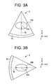
- an elliptical phantom PM having an elliptical cross section in the x-y plane is used as the phantom, as exemplarily shown in Figures 3(a) and (b).
- Figure 3(a) shows a positional relationship between the rotating section 2 and elliptical phantom PM in a certain view
- Figure 3(b) shows their positional relationship in another view.
- the use of the elliptical phantom PM allows a path length 5ca in a certain view and a path length 5cb in another view, for example, to be differentiated even for the same X-ray beam 5c whose intensity is detected by a detector channel ch in the center of the X-ray detector 70.
- a plurality of circular cylindrical phantoms having different diameters may be used one by one.
- Step ST4 Prior to a scan, several kinds of parameters PM for the X-ray CT apparatus 10 are specified (Step ST4) .
- Preferred parameters PM are those affecting the corrective value, and include, for example, the aforementioned width of opening of the X-ray beam 5, the region in a tomographic image to be reconstructed, and the voltage to be applied to the X-ray source XL. Differentiation of the path length of the X-ray beam 5 using the elliptical phantom PM may be considered to be included in variation in the parameters PM.
- the value for the width of opening AP(m) employed is, for example, the width of a slit in the collimator (not shown) disposed adjacent to the X-ray source XL on the side of the X-ray detector 70 for defining the extent of the X-ray beam 5.
- the width may be appropriately changed within a range of, for example, 10 - 60 mm.
- the width of opening AP(0) is relatively small, i.e., of the order of 10 mm, the region in the X-ray detector 70 onto which X-ray beam 5 impinges is small, and the influence by scatter rays is relatively small. It is preferable to thus set the width of opening AP(0) as a baseline to a relatively small width of opening.
- the X-ray CT apparatus 10 After setting the width of opening AP(m), the X-ray CT apparatus 10 is used to scan the elliptical phantom PM, and projection data is acquired (Step ST5).
- a general description on a scan by the X-ray CT apparatus 10 was set out earlier and is omitted here.
- the projection data is obtained for the number of views used in the scan for every detector channel ch.
- the projection data obtained at Step ST5 is defined as projection data D(m).
- the calculation/control apparatus 23 applies first pre-processing to the projection data D(m) obtained at Step ST5, including offset correction and reference correction (Step ST6) .
- the offset correction is a process of correcting an offset value incorporated in the detected data mainly due to the drift of an A-D (analog-to-digital) converter contained in the DAS 20.
- the reference correction is a process for correcting variation in intensity of X-rays emitted from the X-ray source XL.
- X-rays emitted from the X-ray source XL do not always have the same intensity, and the intensity of the emitted X-rays may vary under some conditions.
- the ratio between projection data D(m) from a detector channel generally referred to as a reference channel, i.e., a detector channel ch upon which X-rays not passing through any object always impinge even if an object such as the subject 1 or phantom is present, and projection data D(m) from other detector channels ch can be used to correct the variation in intensity of the emitted X-rays.
- the projection data D(m) after the first pre-processing is designated as data RD(m).
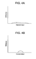
- the graphs shown in Figures 4(a) and (b) show the magnitude of the difference Sub(m) in one detector channel row 7, with the horizontal axis representing the channel index i, and the vertical axis representing the magnitude of the difference Sub(m), in which (a) shows exemplary values in a certain view, and (b) shows exemplary values in another view.
- the area of projection of the elliptical phantom PM onto the X-ray detector 70 is different from view to view, and therefore, a range of the channel indices i having a non-null value of the difference Sub(m) is different from view to view, as shown in Figures 4(a) and (b).
- the calculation/control apparatus 23 calculates the ratio Sub(m)/RD(m) (Step ST8) .
- the calculation of the ratio Sub(m)/RD(m) provides the proportion of the intensity S of scatter rays in the sum of the intensity P of X-rays that directly reach each detector channel ch from the X-ray source XL and the intensity S of scatter rays, i.e., in the value detected by each detector channel ch.
- the ratio Sub(m)/RD(m) for each detector channel ch in each view is also stored in the storage device 40.
- the calculation/control apparatus 23 applies second pre-processing on the data RD(m) calculated at Step ST6 (Step ST9).
- the second pre-processing includes calculation of -log (RD(m)), for example.
- the data RD(m) after the second pre-processing is designated as data LD(m).
- the data LD(m) enables the magnitude of projection data for each detector channel ch to be quantitatively evaluated.
- the value of data LD(m) can be considered to have correlation with the path length. Therefore, the value of the data LD(m) may be regarded as the path length, and the path length to each detector channel ch can be obtained for each view, as shown in Figures 5(a) and (b).
- Figure 5(a) shows exemplary values in a certain view corresponding to Figure 4(a)
- Figure 5(b) shows exemplary values in another view corresponding to Figure 4(b).
- the calculation/control apparatus 23 stores the generated data LD(m) in the storage device 40.
- the calculation/control apparatus 23 accesses the storage device 40 to read the ratio Sub(m)/RD(m) and data LD(m) stored therein, and plots the ratio Sub(m)/RD(m) against the data LD(m) (Step ST10) .
- This process provides a plot PT as shown in Figure 6.
- the horizontal axis represents the value of the data LD(m) as the path length
- the vertical axis represents the value of the ratio Sub(m)/RD(m) as the corrective value S/(S+P). Since the corrective value S/(S+P) is the proportion of the intensity S of scatter rays in the value of the intensity (S+P) detected by each detector channel ch, its maximum value is one.
- Step ST11 the calculation/control apparatus 23 makes decision as to whether the value m of the counter has reached the number of counts n specified at Step ST1 (Step ST11).
- Step ST12 the calculation/control apparatus 23 increments the value m of the counter by one to redefine it as m+1 (Step ST12), and repeats the procedure from Step ST4 to Step ST10.
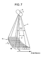
- Figure 7 is a perspective view of a main portion representing the relationship among the X-ray source XL, X-ray focal spot 3, X-ray beam 5 and X-ray detector 70.
- the width of opening AP(m) at Step ST4 is changed so that the width of the X-ray beam 5 varies at least in the column direction (z-axis direction) in the X-ray detector 70, as shown in Figure 7.
- the detecting surface Su of each detector channel ch forms a curve to be directed toward the X-ray focal spot 3 in the channel direction represented by the index i
- the detecting surface Su is flatly arranged in the column direction represented by the index j.
- the width of opening AP is adjusted to enlarge the width of the X-ray beam 5 from, for example, a width L1 to a width L2, whereby the influence by scatter rays is made larger accordingly.
- the width of the X-ray beam 5 is preferably adjusted in the column direction.
- Step ST13 a decision is made here as to whether another circular cylindrical phantom having a different diameter is to be used instead.
- Step ST13 When the process of Step ST2 - ST12 has been completed for all of a plurality of circular cylindrical phantoms having different diameters to be processed, the decision that the phantom will not be replaced is made at Step ST13, and the procedure goes to the next step.
- the circular cylindrical phantoms to be employed are those having a plurality of sizes, such as cross-sectional diameters of 20 cm, 30 cm, 40 cm and the like, for example.
- Step ST13 When the process up to Step ST13 has been completed and the plot PT representing the relationship between the path length and corrective value for each detector channel ch has been obtained for all views, the calculation/control apparatus 23 executes fitting to regress the plot PT to a certain function (Step ST14) .
- the calculation/control apparatus 23 regresses the corrective value to a function of a certain number of orders by, for example, a method of least squares for minimizing the sum of the differences with respect to the plot PT.
- An exemplary graph obtained by the fitting is shown in Figure 6 as a fitting curve graph G1.
- the function to which the plot PT is regressed is preferably one that has a value of zero at a path length of zero.
- the corrective value obtained from the graph G1 has a value correlated with the path length, as can be seen from the graph G1 being a function of the path length.
- the relationship between the path length and corrective value as shown by the graph G1 is stored in the storage device 40 as a correction table.
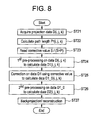
- Figure 8 is a chart showing a procedure of generating tomographic image data using the corrective value in the present embodiment.
- the calculation/control apparatus 23 first conducts a scan on the subject 1 by controlling the X-ray CT apparatus main body 10A.
- the scan provides projection data D(i, j, k) on the subject 1 for a channel index i , column index j , and view index k (Step ST21) .
- the calculation/control apparatus 23 calculates a path length Pr( i , j , k ) of the X-ray beam 5 detected by each detector channel ch through the subject 1 for the channel index i , column index j and view index k , based on the projection data D( i , j , k) (Step ST22) .
- a value obtained by applying first and second pre-processing on the projection data D( i, j, k ) can be regarded as the path length Pr( i , j, k).
- the calculation/control apparatus 23 reads a corrective value based on the path length Pr( i , j, k) calculated at Step ST22 (Step ST23) .
- the calculation/control apparatus 23 accesses the storage device 23 to read a corrective value corresponding to the value of the path length Pr( i , j, k) from the correction table.
- the calculation/control apparatus 23 uses a value after applying the second pre-processing to the corrective value obtained from the correction table based on the fitting curve as shown by the graph G1 as the corrective value S/(S+P) for correction hereinbelow.
- the second pre-processing for calculating the corrective value S/(S+P) is the same as the second pre-processing such as negative logarithm at Step ST9 in Figure 2.
- the corrective value S/(S+P) corresponding to the path length Pr( i , j, k ) can now be obtained for the projection data D( i , j, k ).
- tomographic image data for the subject 1 will be generated by correcting the projection data D( i , j, k ) using the corrective value S/(S+P).
- the calculation/control apparatus 23 applies first pre-processing to the projection data D( i, j, k ) (Step ST24) .
- the first pre-processing at Step ST24 is the same as the first pre-processing such as offset and reference corrections at Step ST6 in Figure 2.
- the data obtained after applying the first pre-processing calculation to the projection data D( i, j, k) is designated as data D1 (i, j, k).
- the calculation/control apparatus 23 corrects the data D1 (i, j, k) using the corrective value obtained at Step ST23 (Step ST25).
- the data D1 (i, j, k) is multiplied by 1-S/(S+P) to calculate corrected data D1_0 (i, j, k).
- the calculation/control apparatus 23 applies second pre-processing to the calculated data D1_0 (i, j, k), for reconstructing tomographic image data (Step ST26).
- the second pre-processing is the same as that at Step ST9 in Figure 2.
- the data D1_0 (i, j, k) after the second pre-processing is designated as data D2 ( i , j , k ).
- the calculation/control apparatus 23 performs arithmetic processing of backprojection and image reconstruction on the data D2 (i, j, k) to generate image data of a certain cross section of the subject 1, i.e., tomographic image data (Step ST27).
- the tomographic image data generated may be stored in the storage device 40, or displayed on the display device 25 after post-processing including prespecified image processing such as rendering.
- a corrective value S/(S+P) for correcting the influence by scatter rays can be precisely obtained by correlating the value with the path length Pr of the X-ray beam 5 through the subject 1 by a calibration scan. Since the corrective value S/(S+P) is generated while taking various parameters such as the width of opening AP of the X-ray beam into account in the calibration scan, the value incorporates various conditions in agreement with the actual scan on the subject 1. Moreover, a portion in which the path length is zero, i.e., the subject 1 is not present, as shown in the graph G1 of the fitting curve in Figure 6, has a corrective value S/(S+P) of zero, and no correction is made.
- the present embodiment is effective especially when the X-ray detector 70 has more rows and the influence by scatter rays is larger.
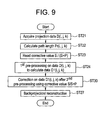
- the procedure for generating tomographic image data using the corrective value S/(S+P) is not limited to that shown in Figure 8, and may be implemented by other procedures. Another procedure for generating tomographic image data using the corrective value S/(S+P) will now be described with reference to Figure 9.
- Figure 9 is a chart showing another procedure for generating tomographic image data using the corrective value S/(S+P).
- Steps ST21 - ST24 shown in Figure 9 is the same as that in Figure 8, and detailed description thereof will be omitted.
- the calculation/control apparatus 23 applies pre-processing similar to the second pre-processing at Step ST26 in Figure 8 to the data D1 (i, j, k) to calculate data D1_1 (i, j, k).
- the data D1_1 (i, j, k) is then multiplied by 1-S/(S+P) to correct the data D1_1 (i, j, k), and calculate the data D2 ( i , j , k ).
- the calculation/control apparatus 23 executes a procedure of backprojection and reconstruction similar to Step ST27 in Figure 8 using the calculated data D2 (i, j, k) to generate tomographic image data of a certain cross-sectional plane of the subject 1.
- tomographic image data for the subject 1 can be generated also by the procedure as shown in Figure 9.
- the present invention is not limited to the aforementioned embodiment and its variation, and several modifications may be done.
- the procedure of the calibration scan is not limited to that shown in the flow chart of Figure 2, and any procedure that provides the same effect can be adopted.
- the corrective value S/(S+P) may incorporate not only the width of opening AP but other parameters including a region in the tomographic image to be reconstructed or the voltage applied to the X-ray source XL.
- x-rays not only x-rays but also other radiation such as gamma rays may be employed.
- a radiation computed tomography apparatus having a configuration for acquiring projection data without using a rotation mechanism may be employed.
Landscapes
- Health & Medical Sciences (AREA)
- Life Sciences & Earth Sciences (AREA)
- Engineering & Computer Science (AREA)
- Medical Informatics (AREA)
- Physics & Mathematics (AREA)
- Nuclear Medicine, Radiotherapy & Molecular Imaging (AREA)
- General Health & Medical Sciences (AREA)
- Radiology & Medical Imaging (AREA)
- Pathology (AREA)
- Heart & Thoracic Surgery (AREA)
- Veterinary Medicine (AREA)
- High Energy & Nuclear Physics (AREA)
- Biophysics (AREA)
- Biomedical Technology (AREA)
- Molecular Biology (AREA)
- Surgery (AREA)
- Animal Behavior & Ethology (AREA)
- Optics & Photonics (AREA)
- Public Health (AREA)
- Theoretical Computer Science (AREA)
- General Physics & Mathematics (AREA)
- Pulmonology (AREA)
- Computer Vision & Pattern Recognition (AREA)
- Chemical & Material Sciences (AREA)
- Analytical Chemistry (AREA)
- Biochemistry (AREA)
- Immunology (AREA)
- Apparatus For Radiation Diagnosis (AREA)
Applications Claiming Priority (2)
| Application Number | Priority Date | Filing Date | Title |
|---|---|---|---|
| JP2003327412A JP3919724B2 (ja) | 2003-09-19 | 2003-09-19 | 放射線計算断層画像装置および断層像データ生成方法 |
| JP2003327412 | 2003-09-19 |
Publications (1)
| Publication Number | Publication Date |
|---|---|
| EP1516588A1 true EP1516588A1 (de) | 2005-03-23 |
Family
ID=34191368
Family Applications (1)
| Application Number | Title | Priority Date | Filing Date |
|---|---|---|---|
| EP04255642A Withdrawn EP1516588A1 (de) | 2003-09-19 | 2004-09-16 | Gerät und Verfahren zur Korrektion von Streustrahlung in der Computertomographie |
Country Status (5)
| Country | Link |
|---|---|
| US (1) | US7372936B2 (de) |
| EP (1) | EP1516588A1 (de) |
| JP (1) | JP3919724B2 (de) |
| KR (1) | KR20050028824A (de) |
| CN (1) | CN100358471C (de) |
Cited By (3)
| Publication number | Priority date | Publication date | Assignee | Title |
|---|---|---|---|---|
| US8064676B2 (en) | 2006-11-14 | 2011-11-22 | Beijing Sinopharm Hundric Medline Info. Tec. Co. Ltd. | Virtual grid imaging method and system for eliminating scattered radiation effect |
| CN105447832A (zh) * | 2015-12-14 | 2016-03-30 | 天津三英精密仪器有限公司 | 一种基于探测器单元标定的ct图像伪影校正方法及应用 |
| US11058369B2 (en) | 2019-11-15 | 2021-07-13 | GE Precision Healthcare LLC | Systems and methods for coherent scatter imaging using a segmented photon-counting detector for computed tomography |
Families Citing this family (21)
| Publication number | Priority date | Publication date | Assignee | Title |
|---|---|---|---|---|
| JP4336661B2 (ja) * | 2005-03-01 | 2009-09-30 | ジーイー・メディカル・システムズ・グローバル・テクノロジー・カンパニー・エルエルシー | X線ct装置および散乱測定方法 |
| KR100725617B1 (ko) * | 2005-07-13 | 2007-06-07 | (주)디알젬 | 직동회전형 볼륨 엑스선 단층촬영장치 |
| JP4679348B2 (ja) * | 2005-11-22 | 2011-04-27 | ジーイー・メディカル・システムズ・グローバル・テクノロジー・カンパニー・エルエルシー | X線ct装置 |
| EP2256519B8 (de) * | 2008-03-21 | 2017-10-04 | Shimadzu Corporation | Verfahren zur korrektur einer zweidimensionalen positionskarte |
| US20140072108A1 (en) * | 2010-07-16 | 2014-03-13 | David P. Rohler | Methods and apparatus for extended low contrast detectability for radiographic imaging systems |
| JP5664880B2 (ja) * | 2010-06-10 | 2015-02-04 | 株式会社島津製作所 | 2次元位置マップ校正方法 |
| FR2966716B1 (fr) | 2010-10-29 | 2012-12-21 | Gen Electric | Methode d'estimation et de correction de la diffusion en mammographie. |
| DE102012204980B4 (de) * | 2012-03-28 | 2021-09-30 | Siemens Healthcare Gmbh | Verfahren zur Rekonstruktion von CT-Bildern mit Streustrahlenkorrektur, insbesondere für Dual-Source CT-Geräte |
| JP6618667B2 (ja) * | 2013-10-18 | 2019-12-11 | キヤノンメディカルシステムズ株式会社 | X線ct装置 |
| JP6342175B2 (ja) * | 2014-02-10 | 2018-06-13 | キヤノンメディカルシステムズ株式会社 | X線ct装置 |
| CN105528800B (zh) * | 2016-01-21 | 2017-04-05 | 上海联影医疗科技有限公司 | 一种计算机断层成像伪影校正方法及装置 |
| PL3362987T3 (pl) | 2015-10-14 | 2022-01-10 | Shanghai United Imaging Healthcare Co., Ltd. | Układ i sposób korekcji obrazu |
| JP6741158B2 (ja) * | 2017-07-25 | 2020-08-19 | 株式会社島津製作所 | 散乱推定方法および画像処理装置 |
| CN112971823B (zh) * | 2017-08-31 | 2023-12-01 | 上海联影医疗科技股份有限公司 | 一种校正杂散射线的方法 |
| US10885678B2 (en) * | 2017-09-29 | 2021-01-05 | International Business Machines Corporation | Facilitating quantum tomography |
| CN107928690B (zh) * | 2017-12-29 | 2021-06-22 | 上海联影医疗科技股份有限公司 | 确定主射线比例方法及图像去散射方法、系统及存储介质 |
| CN111526796B (zh) | 2017-12-29 | 2023-08-25 | 上海联影医疗科技股份有限公司 | 用于图像散射校正的系统和方法 |
| JP7534038B2 (ja) * | 2018-11-30 | 2024-08-14 | アキュレイ インコーポレイテッド | コーンビームコンピュータ断層撮影における最適なパネル読み出しのための非対称散乱フィッティング |
| DE102019203713A1 (de) * | 2019-03-19 | 2020-09-24 | Siemens Healthcare Gmbh | Korrektur einer Unwucht anhand der aufgenommenen Strahlungsdaten |
| CN116172592B (zh) * | 2023-02-27 | 2025-12-19 | 上海联影医疗科技股份有限公司 | 硬化校正方法、装置和存储介质 |
| CN118501190B (zh) * | 2024-07-18 | 2024-11-12 | 苏州奥特兰恩自动化设备有限公司 | 一种基于断层扫描的液晶良品检测方法及系统 |
Citations (1)
| Publication number | Priority date | Publication date | Assignee | Title |
|---|---|---|---|---|
| EP0652537A1 (de) * | 1993-11-10 | 1995-05-10 | Koninklijke Philips Electronics N.V. | Verfahren und Vorrichtung zur Computer-Tomographie |
Family Cites Families (23)
| Publication number | Priority date | Publication date | Assignee | Title |
|---|---|---|---|---|
| GB1571800A (en) * | 1976-01-15 | 1980-07-16 | Emi Ltd | Radiography |
| US4266135A (en) * | 1977-07-01 | 1981-05-05 | Ohio Nuclear, Inc. | Method of determining collimator aperture efficiency and apparatus with an efficient collimator aperture size |
| JPS5594241A (en) | 1979-01-11 | 1980-07-17 | Hitachi Medical Corp | Xxray transverse layer device |
| US4233507A (en) | 1979-05-07 | 1980-11-11 | General Electric Company | Computer tomography table containing calibration and correlation samples |
| US4296329A (en) | 1979-10-22 | 1981-10-20 | General Electric Company | Alignment device for computerized tomography phantoms |
| DE2944147A1 (de) * | 1979-11-02 | 1981-05-14 | Philips Patentverwaltung Gmbh, 2000 Hamburg | Anordnung zur ermittlung der streudichteverteilung in einem ebenen untersuchungsbereich |
| JPS60210087A (ja) * | 1984-04-03 | 1985-10-22 | Toshiba Corp | X線診断装置 |
| US4787098A (en) * | 1987-04-10 | 1988-11-22 | Kabushiki Kaisha Toshiba | Method for obtaining calibrated tomographic image data to correct for collimator width differences |
| US4897788A (en) | 1988-04-18 | 1990-01-30 | General Electric Company | Image correction for computed tomography to remove crosstalk artifacts |
| FR2632749B1 (fr) | 1988-06-10 | 1990-08-24 | Gen Electric Cgr | Procede et systeme d'etalonnage d'un scanner a rayons x en utilisant un ou plusieurs etalons circulaires excentres |
| FR2700909B1 (fr) | 1993-01-27 | 1995-03-17 | Gen Electric Cgr | Dispositif et procédé automatique de calibration géométrique d'un système d'imagerie par rayons X. |
| US5461651A (en) * | 1993-11-17 | 1995-10-24 | General Electric Company | Reconstruction of images in cone beam scanning with rectangular detector elements |
| JP3426677B2 (ja) * | 1994-01-27 | 2003-07-14 | 株式会社日立メディコ | X線ct装置 |
| US5821541A (en) | 1996-02-02 | 1998-10-13 | Tuemer; Tuemay O. | Method and apparatus for radiation detection |
| US5774519A (en) | 1997-01-30 | 1998-06-30 | Analogic Corporation | Method of and apparatus for calibration of CT scanners |
| US6325539B1 (en) | 1998-12-31 | 2001-12-04 | General Electric Company | Calibration simplification for a computed tomograph system |
| JP4398525B2 (ja) * | 1999-01-08 | 2010-01-13 | 株式会社東芝 | X線コンピュータ断層撮影装置 |
| US6275559B1 (en) | 1999-10-08 | 2001-08-14 | General Electric Company | Method and system for diagnosing faults in imaging scanners |
| DE10047720A1 (de) | 2000-09-27 | 2002-04-11 | Philips Corp Intellectual Pty | Vorrichtung und Verfahren zur Erzeugung eines Röntgen-Computertomogramms mit einer Streustrahlungskorrektur |
| US6473488B2 (en) * | 2000-12-20 | 2002-10-29 | Cedara Software Corp. | Three dimensional image reconstruction from single plane X-ray fluorograms |
| US20030128801A1 (en) * | 2002-01-07 | 2003-07-10 | Multi-Dimensional Imaging, Inc. | Multi-modality apparatus for dynamic anatomical, physiological and molecular imaging |
| DE10238322A1 (de) * | 2002-08-21 | 2004-03-11 | Siemens Ag | Retrospektive bzw. fenstergesteuerte Filterung von Bildern zur Adaption von Schärfe und Rauschen in der Computer-Tomographie |
| SE526371C2 (sv) * | 2003-12-01 | 2005-08-30 | Xcounter Ab | Anordning och förfarande för att erhålla tomografi-, tomosyntes- och stillbildsdata för ett objekt |
-
2003
- 2003-09-19 JP JP2003327412A patent/JP3919724B2/ja not_active Expired - Fee Related
-
2004
- 2004-09-14 US US10/940,904 patent/US7372936B2/en not_active Expired - Lifetime
- 2004-09-16 EP EP04255642A patent/EP1516588A1/de not_active Withdrawn
- 2004-09-17 KR KR1020040074448A patent/KR20050028824A/ko not_active Withdrawn
- 2004-09-20 CN CNB2004100798094A patent/CN100358471C/zh not_active Expired - Lifetime
Patent Citations (1)
| Publication number | Priority date | Publication date | Assignee | Title |
|---|---|---|---|---|
| EP0652537A1 (de) * | 1993-11-10 | 1995-05-10 | Koninklijke Philips Electronics N.V. | Verfahren und Vorrichtung zur Computer-Tomographie |
Non-Patent Citations (3)
| Title |
|---|
| ENDO M ET AL: "Development and performance evaluation of the first model of 4D CT-scanner", 2002 IEEE NUCLEAR SCIENCE SYMPOSIUM CONFERENCE RECORD. / 2002 IEEE NUCLEAR SCIENCE SYMPOSIUM AND MEDICAL IMAGING CONFERENCE. NORFOLK, VA, NOV. 10 - 16, 2002, IEEE NUCLEAR SCIENCE SYMPOSIUM CONFERENCE RECORD, NEW YORK, NY : IEEE, US, vol. VOL. 3 OF 3, 10 November 2002 (2002-11-10), pages 1824 - 1828, XP010663877, ISBN: 0-7803-7636-6 * |
| JOSEPH P M ET AL: "The effects of scatter in x-ray computed tomography", MEDICAL PHYSICS, AMERICAN INSTITUTE OF PHYSICS. NEW YORK, US, vol. 9, no. 4, July 1982 (1982-07-01), pages 464 - 472, XP002274892, ISSN: 0094-2405 * |
| OHNESORGE B ET AL: "Efficient object scatter correction algorithm for third and fourth generation CT scanners", EUROPEAN RADIOLOGY, SPRINGER INTERNATIONAL, BERLIN, DE, vol. 9, no. 3, 1999, pages 563 - 569, XP002274890, ISSN: 0938-7994 * |
Cited By (4)
| Publication number | Priority date | Publication date | Assignee | Title |
|---|---|---|---|---|
| US8064676B2 (en) | 2006-11-14 | 2011-11-22 | Beijing Sinopharm Hundric Medline Info. Tec. Co. Ltd. | Virtual grid imaging method and system for eliminating scattered radiation effect |
| CN105447832A (zh) * | 2015-12-14 | 2016-03-30 | 天津三英精密仪器有限公司 | 一种基于探测器单元标定的ct图像伪影校正方法及应用 |
| CN105447832B (zh) * | 2015-12-14 | 2018-03-02 | 天津三英精密仪器有限公司 | 一种基于探测器单元标定的ct图像伪影校正方法及应用 |
| US11058369B2 (en) | 2019-11-15 | 2021-07-13 | GE Precision Healthcare LLC | Systems and methods for coherent scatter imaging using a segmented photon-counting detector for computed tomography |
Also Published As
| Publication number | Publication date |
|---|---|
| CN100358471C (zh) | 2008-01-02 |
| KR20050028824A (ko) | 2005-03-23 |
| US20050063518A1 (en) | 2005-03-24 |
| CN1596828A (zh) | 2005-03-23 |
| JP2005087588A (ja) | 2005-04-07 |
| US7372936B2 (en) | 2008-05-13 |
| JP3919724B2 (ja) | 2007-05-30 |
Similar Documents
| Publication | Publication Date | Title |
|---|---|---|
| EP1516588A1 (de) | Gerät und Verfahren zur Korrektion von Streustrahlung in der Computertomographie | |
| US6421411B1 (en) | Methods and apparatus for helical image artifact reduction | |
| US6320929B1 (en) | Method for scanning an examination subject with a CT device | |
| US7085345B2 (en) | Radiation computed tomographic imaging apparatus and radiation detector for use therein | |
| US7929747B2 (en) | System and method for estimating data missing from CT imaging projections | |
| US6404844B1 (en) | Tomographic imaging scan condition determining method, tomographic imaging method and X-ray CT apparatus | |
| JP3864106B2 (ja) | 透過x線データ獲得装置およびx線断層像撮影装置 | |
| US7920672B2 (en) | X-ray detector gain calibration depending on the fraction of scattered radiation | |
| JP2002531199A (ja) | 石灰化のレベル付けを行う方法と装置 | |
| CN100384377C (zh) | 辐射计算机断层扫描设备 | |
| CN104039232B (zh) | X射线ct装置及图像重构方法 | |
| KR20070024430A (ko) | X선 ct 장치 | |
| JP2007181623A (ja) | X線ct装置 | |
| EP3835830B1 (de) | Systeme und methoden zur abschätzung einer brennpunktbewegung und zur berechnung einer entspechenden korrektur | |
| EP0985379A1 (de) | Strahlungstomographieverfahren und Gerät | |
| JP4397513B2 (ja) | X線ct装置 | |
| US7359476B2 (en) | Radiation tomographic imaging apparatus and radiation tomographic imaging method, and image producing apparatus | |
| JP2008012206A (ja) | X線断層撮影装置 | |
| JP2001112749A (ja) | プロジェクションデータ補正方法および装置並びに放射線断層撮像装置 | |
| US6366637B1 (en) | Methods and apparatus for generating thin-slice imaging data on a multi-slice imaging system | |
| JP5117792B2 (ja) | 記憶媒体及びx線ctシステム | |
| EP1952766B1 (de) | Röntgen-CT-Vorrichtung | |
| JP2006239118A (ja) | X線ct装置 | |
| JP4509507B2 (ja) | 放射線計算断層画像装置および断層画像生成方法 | |
| JP4342563B2 (ja) | 放射線計算断層画像装置 |
Legal Events
| Date | Code | Title | Description |
|---|---|---|---|
| PUAI | Public reference made under article 153(3) epc to a published international application that has entered the european phase |
Free format text: ORIGINAL CODE: 0009012 |
|
| AK | Designated contracting states |
Kind code of ref document: A1 Designated state(s): AT BE BG CH CY CZ DE DK EE ES FI FR GB GR HU IE IT LI LU MC NL PL PT RO SE SI SK TR |
|
| AX | Request for extension of the european patent |
Extension state: AL HR LT LV MK |
|
| 17P | Request for examination filed |
Effective date: 20050923 |
|
| AKX | Designation fees paid |
Designated state(s): DE FR GB |
|
| 17Q | First examination report despatched |
Effective date: 20100727 |
|
| STAA | Information on the status of an ep patent application or granted ep patent |
Free format text: STATUS: THE APPLICATION IS DEEMED TO BE WITHDRAWN |
|
| 18D | Application deemed to be withdrawn |
Effective date: 20101207 |