EP1516587B1 - Vorrichtung sowie Verfahren zur Bewertung des Arbeitskomforts - Google Patents
Vorrichtung sowie Verfahren zur Bewertung des Arbeitskomforts Download PDFInfo
- Publication number
- EP1516587B1 EP1516587B1 EP04022244A EP04022244A EP1516587B1 EP 1516587 B1 EP1516587 B1 EP 1516587B1 EP 04022244 A EP04022244 A EP 04022244A EP 04022244 A EP04022244 A EP 04022244A EP 1516587 B1 EP1516587 B1 EP 1516587B1
- Authority
- EP
- European Patent Office
- Prior art keywords
- work
- muscles
- comfort
- intensity
- level
- Prior art date
- Legal status (The legal status is an assumption and is not a legal conclusion. Google has not performed a legal analysis and makes no representation as to the accuracy of the status listed.)
- Expired - Lifetime
Links
Images


Classifications
-
- A—HUMAN NECESSITIES
- A61—MEDICAL OR VETERINARY SCIENCE; HYGIENE
- A61B—DIAGNOSIS; SURGERY; IDENTIFICATION
- A61B5/00—Measuring for diagnostic purposes; Identification of persons
- A61B5/16—Devices for psychotechnics; Testing reaction times ; Devices for evaluating the psychological state
- A61B5/18—Devices for psychotechnics; Testing reaction times ; Devices for evaluating the psychological state for vehicle drivers or machine operators
-
- A—HUMAN NECESSITIES
- A61—MEDICAL OR VETERINARY SCIENCE; HYGIENE
- A61B—DIAGNOSIS; SURGERY; IDENTIFICATION
- A61B5/00—Measuring for diagnostic purposes; Identification of persons
- A61B5/22—Ergometry; Measuring muscular strength or the force of a muscular blow
- A61B5/224—Measuring muscular strength
- A61B5/228—Measuring muscular strength of masticatory organs, e.g. detecting dental force
Definitions
- the present invention relates to a work comfort evaluating device and method for evaluating a level of comfort of work by measuring myoelectric potentials of plural deltoid muscles when the work is done by antagonistic activities of the deltoid muscles. More particularly, the invention relates to a device and method for evaluating a steering comfort of a vehicle.
- an electromyogram depicting signal waveforms of myoelectric potentials of a worker is used, and loads imparted to the muscles of the worker are quantitatively grasped. Since the measurement itself of the myoelectric potential is simple and good in its adaptation, it is thought that a level of the work load imparted when given work is done can properly be evaluated when the electromyogram is used. Further, there is a possibility that the evaluating method using the electromyogram is applied to the steering operation of the vehicle by the driver.
- JP 2002-225585 A discloses a technique in which a myoelectric potential of a muscle acting to extend the arm and a myoelectric potential of another muscle acting to contract the arm are both measured, a value (conflict value) concerning a conflict of those two myoelectric potentials is calculated, and a level of driving load on the driver is determined based on the conflict value. More specifically, myoelectric potentials of the muscles of the driver which conflictingly act are measured by using myoelectric potential sensors, and a conflict feature quantity is calculated from a conflict value of the myoelectric potentials measured. When the calculated conflict feature quantity exceeds a predetermined threshold value, it is judged that the driving load on the driver has increased (paragraphs [0031] to [0038] in JP 2002-225585 A ).
- the myoelectric potentials are measured for a long time, for example, 10 minutes, 8 minutes or 5 minutes, and a conflict value is calculated based on the measurement results.
- a conflict feature quantity for calibration such as maximum values and average values, is calculated from the conflict value obtained by the long-time measurement.
- the threshold value in question is determined by multiplying the calculated feature quantity by a preset coefficient.
- the long time measurement of 10 minutes for example, is required.
- the driving load on the driver cannot be judged.
- JP 2002-225585 A the data of the previous driving by the driver is used as a reference (paragraph [0040] in JP 2002-225585 A ).
- the myoelectric potential level frequently takes a different value when the myoelectric potential is measured because every time the sensors are stuck onto parts of the muscles before the measurement. If the data of the previous driving is used, which contains the myoelectric potential level that is probably different from the level of the current measurement, the judgment of the driving load on the driver will be erroneous. That is, the conflict feature quantity for calibration, which is used for determining the threshold value, is calculated from the myoelectric potential which will take a different value every time the detecting sensors are stuck. As a result, the conflict feature quantity for calibration also takes a different value every time the sensors are stuck. Accordingly, if the threshold value is determined by multiplying the conflict feature quantity for calibration by a fixed coefficient, judgment of the driving load on the driver will be erroneous.
- the driving load on the driver disclosed in JP 2002-225585 A is a combination of a mental burden as to whether the driving is easy for the driver and a physical load when the driver actually drives. Accordingly, in a case where a large steering force is required for operating the steering wheel depending on the type of tires mounted, the physical load imparted to the steering wheel is large and the driving load increases. In this case, the steering force is large and a stable steering is secured, giving the driver secures a sense of safety and making the mental load less. However, the increase of the steering force results in an increase of the driving load.
- JP 2002-225585 A the driving load on the driver is evaluated by using threshold values preset for respective running modes of high-speed cruising, highway congestion and city-area driving. Therefore, it is impossible to know a difference of the driving load caused by the mental burden on the drive in the high-speed cruising mode from the mental load in the highway congestion mode.
- JP 2002230699 A relates to an operation load judgment device characterized by providing a contention value calculation means to compute the value about muscular contention and an operation load judging means to judge the magnitude of the operation load of a driver based on the value about said contention, based on the myoelectric potential of two or more muscles.
- an object of the present invention is to provide a work comfort evaluating device and method for evaluating a level of comfort of work particularly by measuring myoelectric potentials of plural deltoid muscles when the work is done by antagonistic activities of the deltoid muscles, with which a level of comfort of work can be quantitatively evaluated from short-time measurement results.
- the present invention provides a work comfort evaluating device for evaluating a level of comfort of work as defined in claims 1 or 7. Preferred embodiments are defined in dependent claims.
- the antagonistic activities of the muscles generally means that one muscle contracts while the other relaxes if there are two muscles cooperatively act to perform a piece of work.
- the plural muscles are a pair of muscles located at right and left parts of the human body. More preferably, the pair of muscles are deltoid muscles of a shoulder of the human body.
- the work load intensity calculating part calculates a level of the work load intensity from the myoelectric potential waveforms of the muscles. Then, the work load intensity calculating part more preferably calculates intensities of muscular loads imparted to the muscles in the work from the myoelectric potential waveforms of the muscles, and averages and smoothes the calculated muscular load intensities in an averaging process to thereby calculate levels of the work load intensities. Then, the averaging process may be a geometric averaging process.
- the work is a work in which the muscles cooperate to cause an object to be operated to dynamically behave
- the work load intensity calculating part calculates a level of the work load intensity by measuring a physical quantity representing a dynamic behavior of the object operated by the work.
- An exemplary signal processing part calculates a geometrical average of the myoelectric potential waveforms of the muscles, and calculates root mean square values of the a geometrical average within a predetermined period, whereby the synchronous contraction intensity is generated.
- the work may be a driving of a vehicle that is performed by a driver turning a steering wheel.
- the invention also provides a work comfort evaluating method for evaluating a level of comfort of a work as defined in claims 6 and 8.
- a level of comfort of work can be quantitatively evaluated from short-time measurement results.
- the present invention which evaluates a work comfort by a level of mental stress from the short-time measurement results, does not have to take a longer time, for example 10 minutes, before a work comfort is evaluated, compared to a conventional method.
- the present invention normalizes the synchronous contraction intensity by the level of the work load intensity, thereby a rate of synchronous contraction intensity which increases as the mental stress is stronger, in the work-load intensity is obtained.
- a work comfort of driver's steering operation can be evaluated irrespective of various driving modes, a high-speed cruising mode, highway congestion mode, city-area driving mode and so on.
- Fig. 1 is a schematic block diagram showing a steering comfort evaluating device 10 as a work comfort evaluating device of the invention applied to a driver's steering operation.
- the steering comfort evaluating device 10 is a device for evaluating a level of comfort of steering operation by a driver who drives a vehicle.
- the steering comfort evaluating device 10 is made up of myoelectric potential detecting sensors 12 and 14 for detecting myoelectric potentials at right and left deltoid muscles of the driver, an electrode 16, an amplifier 18 for amplifying myoelectric potentials derived from the potential detecting sensors 12 and 14, a processor unit 20 for evaluating a level of steering comfort based on time-series waveforms of the amplified myoelectric potentials at the right and left deltoid muscles, and a monitor 22 for monitoring the result of the valuation.
- the myoelectric potential detecting sensor 12 is a sensor for sensing a myoelectric potential of the deltoid muscle of the left shoulder of the driver.
- the detecting senor 12 is formed with a pair of Ag/AgCl dish-shaped electrodes. Those paired electrodes are stuck onto a surface part of the left shoulder where the deltoid muscle is located, while being spaced apart from each other a predetermined distance of several milimeters, for example, 5 mm.
- the myoelectric potential detecting sensor 14 is a sensor for detecting a myoelectric potential of the deltoid muscle of the right shoulder of the driver.
- the detecting senor 14 like the detecting sensor 12, is formed with a pair of Ag/Ag CL dish-shaped electrodes. Those paired electrodes are stuck onto a surface part of the right shoulder where the deltoid muscle is located, while being spaced apart from each other a predetermined distance of several milimeters, for example, 5 mm.
- a material for those potential detecting sensors 12 and 14 is not limited to Ag/Ag CL, but may be any of other suitable materials, such as Ag or stainless steel.
- each electrode is scrubbed with a suitable means, and cleaned by using alcohol, and then are attached to the skin surface by using electrode paste. In this case, the cleaning operation is continued till an electric resistance is reduced to 30 k ⁇ (preferably 5 k ⁇ ).
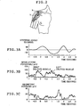
- the paired electrodes are attached onto a venter of the muscle in a state where those electrodes are arranged in parallel with the muscular fiber. As shown in Fig. 2 , the electrodes are attached to positions Y spaced in a longitudinal direction of the arm from an end X of the outer side of the clavicle by a distance corresponding to three fingers put together, with the predetermined distance left between those electrodes.
- the electrode 16 is an ground electrode to be attached to an earlobe of the driver, which is an electrically inactive position, in order to keep a potential of the driver constant. Use of the electrode 16 ensures an exact measurement carried out by the potential detecting sensors 12 and 14.
- the electrode 16, connected to the amplifier 18, is grounded via the amplifier 18.
- the amplifier 18 is connected to the detecting sensors 12 and 14 by means of lead wires.
- the amplifier is a known operational amplifier for amplifying myoelectric potentials detected by the detecting sensors 12 and 14.
- the myoelectric potentials which are detected by the detecting sensors 12 and 14 and amplified by the amplifier, are transmitted to the processor unit 20.
- the processor unit 20 contains a signal processing part 24, a work load intensity calculating part 25, and a comfort evaluating part 26.
- the processor unit 20 is a unit containing a computer.
- the signal processing part 24, the work load intensity calculating part 25, and the comfort evaluating part 26 exhibit their own functions when the program is executed.
- the signal processing part 24, the work load intensity calculating part 25, and the comfort evaluating part 26 may be constructed with which dedicated circuits.
- the signal processing part 24 samples time-series data of myoelectric potentials at the two deltoid muscles to generate myoelectric potential waveforms and calculates a synchronous contraction intensity by using the myoelectric potential waveforms.
- the time-series data of the myoelectric potentials are sampled and subjected to full-wave rectification.
- the rectified waveforms are smoothed by smoothing filters (low-pass filters) to generate signal waveforms of the myoelectric potentials (myoelectric potential waveforms).
- a geometric average (a square root of the product of the myoelectric potential waveforms) of the two myoelectric potential waveforms at the same time point is calculated.
- a synchronous contraction waveform generated when the right and left deltoid muscles simultaneously and synchronously contract is formed by using the average values thus obtained.
- a root means square (RMS) of the synchronous contraction waveform is calculated, and the calculated RMS is used as a synchronous contraction intensity.
- RMS root means square
- the RMS value is a square root of the sum of squares of the deviation of the waveforms from the mean value (simple addition mean value) during a predetermined period.
- the predetermined period is, for example, 0.5 to 10 seconds. It is evident that the synchronous contraction waveform in the present invention is not limited to the waveform generated by calculating a geometric average of the two myoelectric potential waveforms. For example, the myoelectric potential waveform that is the smaller in value of the two myoelectric potential waveforms may be used for the synchronous contraction waveform.
- the synchronous contraction waveform by calculating a geometric average of the two myoelectric potential waveforms, with an intention of lessening deterioration of the synchronous contraction waveform, where the deterioration arises from a level variation of the myoelectric potential caused every time the potential detecting sensors 12 and 14 are stuck.
- the signal processing part 24 supplies to the work load intensity calculating part 25 the signal waveforms of the myoelectric potentials, which are formed through the smoothing process.
- Fig, 3A typically shows time-series data of steering angles produced when a driver turns the steering wheel.
- Fig. 3B shows myoelectric potential waveforms of the right and left deltoid muscles of the driver, which are formed by performing full-wave rectification on the myoelectric potential waveforms and smoothing them by smoothing filters.
- the myoelectric potential signal originally contains high frequency components generated when the muscle contracts. However, a force generated when the muscle contracts does not contain high frequency components. The reason for performing full-wave rectification on and smoothing the myoelectric potential waveforms is to make the myoelectric potential waveforms correspond to the force generated when the muscle contracts.
- Fig. 3A typically shows time-series data of steering angles produced when a driver turns the steering wheel.
- Fig. 3B shows myoelectric potential waveforms of the right and left deltoid muscles of the driver, which are formed by performing full-wave rectification on the myoelectric potential waveforms and smoothing them by smoothing filters.
- FIG. 3C shows a synchronous contraction waveform that is obtained by calculating a geometric average of the myoelectric potential waveforms of the right and left deltoid muscles shown in Fig. 3B .
- An RMS value of the synchronous contraction waveform for a predetermined period is calculated, whereby a synchronous contraction intensity is obtained.
- the work load intensity calculating part 25 calculates a level of the work load intensity in the steering operation by the driver by using the myoelectric potential waveforms supplied from the signal processing part 24. Specifically, muscular load intensities of the right and left deltoid muscles when the driver operates the steering wheel are calculated from the myoelectric potential waveforms. Those muscular load intensities are averaged. A level of work load intensity is calculated together with the calculation of a synchronous contraction intensity. The calculation of the work load intensity is performed together with the generation of the synchronous contraction intensity. The muscular load intensity is obtained by calculating an RMS value of the myoelectric potential waveform of each of the right and left deltoid muscles as shown in Fig. 3B .
- Work-load intensities of the right and left deltoid muscles when those deltoid muscles engage in the steering operation are calculated by averaging the muscular load intensities of the right and left deltoid muscles.
- the work load intensity is obtained by calculating separately the muscular load intensities of the right and left deltoid muscles and averaging those calculated ones.
- the averaging process is not limited to the geometric average process, but may be a normal average (simple addition mean) process; however, the geometric average process is preferable from the point of view of the accuracy.
- the work load intensity calculated is supplied to the comfort evaluating part 26.
- the comfort evaluating part 26 calculates a synchronous contraction rate, which represents a level of a driver's mental stress by using the synchronous contraction intensities and the work load intensity, which are supplied from the signal processing part 24 and the work load intensity calculating part 25, and evaluates a level of comfort of the driver's steering operation based on the synchronous contraction rate.
- the synchronous contraction rate to be calculated represents a ratio of the synchronous contraction intensity which indicates a mental stress for the work load intensity when the synchronous contraction intensity representing a level of the mental stress is normalized by dividing the synchronous contraction intensity by the work load intensity.
- An evaluation of the driver's comfort in the steering operation is performed in the following manner, for example.
- Comfort levels of the driver when he/she operates the steering wheel are arranged in ranks.
- a synchronous contraction rate calculated is compared with preset values for the respective ranks.
- the comfort level is evaluated based on the comparison result.
- An evaluation of the driver's comfort in the steering operation may also be performed in the following manner, for example.
- a frequency at which the synchronous contraction rate falls within a predetermined segment within a predetermined time is compared with the frequencies preset to rank comfort levels of the steering operation by the driver.
- the comfort level is evaluated based on the comparison result.
- Such evaluation results are sent to the monitor 22 to be displayed.
- the steering comfort evaluating device 10 calculates a synchronous contraction waveform from the myoelectric potential waveforms of the right and left deltoid muscles, and calculates a synchronous contraction intensity. Further, the steering comfort evaluating device calculates a work load intensity from the myoelectric potential waveforms. The steering comfort evaluating device also calculates a synchronous contraction rate representing a level of mental stress of the driver when he/she operates the steering wheel, by using the calculated synchronous contraction intensity and the work load intensity. Finally, the steering a level of comfort evaluating device evaluates a level of steering comfort of the driver based on the synchronous contraction rate.
- the driver turns the steering wheel.
- the driver angularly moves the left hand gripping the wheel in an upward direction.
- the deltoid muscle of the driver's left shoulder contracts actively.
- the right hand of the driver is merely put on the steering wheel and moves passively. Accordingly, at this time, the deltoid muscle of the right shoulder relaxes.
- the deltoid muscle of the driver's left shoulder relaxes, while the deltoid muscle of the right shoulder contracts.
- the steering operation is performed by the driver in such a manner that one of the right and left deltoid muscles of the human body, which are symmetrically disposed as laterally viewed, contracts, while the other relaxes. That is, the steering operation is done that is antagonistically done by the paired muscles that are laterally symmetrical.
- the driver grips the steering wheel by excessive force for handling because the driver has some mental burden when the driver is hindered from smooth steering operation and incessantly grips the steering wheel in a strained condition, for example.
- the steering operation is difficult and the driver strains himself.
- the right and left deltoid muscles synchronous contract also in the steering operation that is done through the antagonistic activities of the right and left deltoid muscles.
- one muscle contracts when it should relax, simultaneously with the straining staete of the other muscle that should be strained.
- the one muscle generates a myoelectric potential.
- a waveform of this myoelectric potential is called a synchronous contraction waveform.
- the inventors of the present invention found the fact that steering easiness of the vehicle and controllability of the vehicle by the steering operation can be evaluated by normalizing the intensity or frequency of the synchronous contraction by using the work load intensity.
- the calculation for obtaining the work load level in the steering operation done by the driver is not limited to the calculation using the myoelectric potentials at the right and left deltoid muscles.
- the steering comfort evaluating device 10 may take any configuration if the muscles antagonistically used in the steering operation are used as objects of which myoelectric potentials are to be measured.
- the biceps brachii muscle and the triceps brachii muscle may be treated as the paired muscles that antagonistically act, and used as the objects of which myoelectric potentials are to be measured.
- Plural pairs of antagonistically acting muscles may be used. In this case, the myoelectric potentials of those muscle pairs may be measured in the following manner.
- Those muscle pairs are classified into two groups: one group consisting of muscles which simultaneously contract, and the other group consisting of muscles which simultaneously relax.
- the myoelectric potentials of those muscles of each group are multiplied or averaged to thereby form two myoelectric potential waveforms.
- the thus obtained myoelectric potential waveforms of those two groups are handled similarly to the right and left deltoid muscle waveforms as already described, to thereby calculate the synchronous contraction rate.
- the work load level is calculated by using the myoelectric potentials of the muscles in the embodiment described above, it may be calculated in any of other suitable ways.
- a steering torque of the steering wheel is measured and a steering angular velocity is measured in addition to the steering torque, thereby to calculate a steering operation energy based on the measurement value or values.
- the steering torque or the operation energy may be used as the work load level.
- a lateral acceleration or a yaw angular velocity of the vehicle, which are generated when the steering wheel is turned is measured. The result of the measurement is used as the work load level in the steering operation.
- the work load intensity calculating part 25 may calculate a work load intensity by measuring physical quantities representing a dynamic behavior of the object (the steering wheel, the vehicle, or the like) having been operated.
- Fig. 4 is a flow chart showing steps for evaluating a level of steering comfort of a driver in a steering comfort evaluating method according to the present invention.
- the myoelectric potential detecting sensors 12 and 14 are stuck onto surface parts of the right and left shoulders where the right and left deltoid muscles of the driver are located (step 100).
- the electrode 16 is stuck onto the earlobe of the driver.
- step S102 After the sticking of the potential detecting sensors 12 and 14, myoelectric potentials at the right and left deltoid muscles of the driver in driving are measured (step S102).
- signals of the myoelectric potentials acquired by the myoelectric potential measurement are sampled, A/D converted, and subjected to full-wave rectification, and thereafter smoothed by the smoothing filters (low-pass filters) to thereby form myoelectric potential waveforms of the right and left deltoid muscles as shown in Fig. 3B (step S104).
- the reason for performing full-wave rectification on and smoothing the myoelectric potential waveforms is to make the myoelectric potential waveforms correspond to the force generated when the muscle contracts, because the myoelectric potential signals are signals containing high frequency components.
- the generated myoelectric potential waveforms of the right and left deltoid muscles are averaged to thereby form a synchronous contraction waveform as shown in Fig. 3C (step S104).
- a geometric averaging process for example, is preferably used for the averaging process.
- the geometric averaging process is carried out by calculating a square root of the product of the right and left deltoid muscle waveforms. Therefore, the geometric average of the myoelectric potential waveform of small level and the waveform of large level is more affected by the myoelectric potential waveform of the small level and the average value is small.
- the small value indicates a level of contraction of the muscle owing to mental stress although the muscle should not contract.
- the synchronous contraction waveform can efficiently be calculated by utilizing the geometric average process.
- the synchronous contraction waveform in the present invention is not limited to the waveform calculated by using the geometric average.
- the two myoelectric potential waveforms may be compared, and the myoelectric potential waveform having the smaller values may be used as the synchronous contraction waveform.
- an RMS value of the synchronous contraction waveform is calculated for the synchronous contraction intensity (step S106). The RMS value is calculated at an interval of 0.1 to 0.5 second.
- the work load intensities of the right and left deltoid muscles by using the myoelectric potential waveforms are calculated (step S107).
- the work load intensity is obtained by calculating the muscular load intensities of the right and left deltoid muscles by using the myoelectric potential waveforms of those muscles and averaging the calculated muscular load intensities.
- the muscular load intensity is an RMS value of the myoelectric potential waveform, for example, and the averaging process is a geometric averaging process.
- the work load intensity is obtained by calculating the muscular load intensities of the right and left deltoid muscles and averaging the calculated muscular loads.
- the work load intensity may also be obtained in the following manner. When the driver operates a specific object to be operated, such as a steering wheel, physical quantities representing a dynamic behavior of the object having been operated is measured, and the result of the measurement is used as the work load intensity.
- an RMS value is calculated to obtain the synchronous contraction intensity, and another RMS value is calculated to obtain the muscular load intensity. It is preferable that those two RMS values are obtained within the same period of time.
- a synchronous contraction rate is calculated by using the thus calculated synchronous contraction intensity and the work load intensity (step S108).
- the calculated synchronous contraction rate is a rate obtained when the synchronous contraction intensity is normalized by dividing it by the work load intensity.
- This rate is a rate of the synchronous contraction rate representative of an intensity versus an intensity at which each muscle receives work load, where the muscles, which do not contract normally, simultaneously and synchronously contract because of mental stress. Therefore, it is evaluated that when the synchronous contraction rate is large, the driver works with great mental stress.
- a level of comfort representing a level of the mental stress is evaluated by using such a synchronous contraction rate (step S110).
- a method of evaluating the level of comfort by using the synchronous contraction rate is not specifically limited.
- the level of comfort may be directly evaluated by using a value of the synchronous contraction rate.
- levels of comfort for work to be done are arranged in several ranks.
- a threshold value of the synchronous contraction rate is set for each comfort level. When a calculated synchronous contraction rate within the threshold value continues for a predetermined period, it is evaluated that the comfort level of the work is within the threshold value.
- plural myoelectric potentials of the muscles that antagonistically act are measured, and the level of comfort of the driver that momently changes when he/she operates the steering wheel can be evaluated based on the result of the measurement that is performed for a short time.
- Fig. 5 shows average values and standard deviations of the synchronous contraction rates when the driver drives a 2-litre sedan type car with various types of tires mounted thereon and changes lanes on the road. Measurement was repeated five times.
- the abscissa of a graph of Fig. 5 represents test specifications A to E when the driver performed lane-changing with various types of tires.
- the test specifications A to E will be described later.
- NVH NVH
- STL a studless tire
- HTP indicates a tire having a good drivability.
- Table 1 further contains a size of each tire type, a cornering power CP f at a front wheel load of the vehicle when the tires are mounted, and another cornering power CP r at a rear wheel load.
- Table 2 shows five test specifications (A to E) based on combinations of three types of tires, NVH, STL, and HPT.
- a to C the same type of tires are mounted on the front wheel and the rear wheel.
- D tires of the HPT type are mounted on the front wheels
- tires of the NVH type are mounted on the rear wheels.
- E tires of the NVH type are mounted on the front wheels
- tires of the HPT type are mounted on the rear wheels.
- the types of tires mounted on the front wheels and on the rear wheels are different in the test specification D and E, so as to change the steering characteristic.
- the steering characteristic in the test specification D is more oversteer than the test specifications A to C.
- the steering characteristic in the test specification E is more understeer than the test specifications A to C.
- the synchronous contraction rate in the test specification C is the smallest of all the synchronous contraction rates in the test specifications, and that in the test specification D is the largest.
- Table 2 Test Specification front wheels/Rear wheels A NVH/NVH B STL/STL C HPT/HPT D HPT/NVH E NVH/HPT
- Fig. 6 is a scatter diagram showing a relationship between a yawing resonance frequency as a vehicle characteristic and a synchronous contraction rate obtained in the manner mentioned above.
- the yawing resonance frequencies were obtained for all the five test specifications A to E.
- the yawing resonance frequency is one of factors which affect the steering performance of the vehicle. As the yawing frequency becomes higher, a vehicle responds to the steering operation faster and more stably, putting less mental burden on the driver. Therefore, as the yawing frequency becomes higher, a level of steering comfort becomes higher.
- the synchronous contraction rate indicates easiness of the steering operation by the driver, that is, an index indicating a level of mental stress at the time of steering.
- Fig. 7A is a graph showing waveforms of myoelectric potentials at the right and left deltoid muscles when the vehicle changes traffic lanes on the road. As seen from Fig.7A , the myoelectric potential waveforms of the right and left deltoid muscles antagonistically act (when one of the deltoid muscles contracts, the other relaxes).
- Fig. 7B is a graph showing a relationship between a potential difference between the myoelectric potential waveforms at the right and left deltoid muscles, and a steering torque variation of the steering wheel measured when it is actually turned.
- a variation of the steering torque resembles a variation of the potential difference between the myoelectric potential waveforms at the right and left deltoid muscles.
- the steering wheel is turned through the antagonistic activities of the right and left deltoid muscles, and that the myoelectric potential waveform reflects physical quantities, e.g., a steering torque indicating a motion of the steering wheel. Therefore, the steering torque measured may be used as an index of an intensity of work load imparted to the deltoid muscles.
- a steering energy in the steering operation done by the driver which is obtained by multiplying the steering torque by the steering angular velocity, may also be used as an index of the work load intensity.
- physical quantities such as a yaw rate indicating a dynamic behavior of the vehicle, which is generated by the steering operation, and a lateral acceleration, may be used as an index of the work load intensity.
- a level of mental stress at work can be properly evaluated by dividing a synchronous contraction intensity of the muscles when one piece of work is done through cooperative actions of plural muscles that antagonistically act, by a work load intensity concurrently calculated.
Landscapes
- Health & Medical Sciences (AREA)
- Life Sciences & Earth Sciences (AREA)
- Engineering & Computer Science (AREA)
- Pathology (AREA)
- Heart & Thoracic Surgery (AREA)
- Hospice & Palliative Care (AREA)
- Psychiatry (AREA)
- Psychology (AREA)
- Social Psychology (AREA)
- Physics & Mathematics (AREA)
- Developmental Disabilities (AREA)
- Biophysics (AREA)
- Child & Adolescent Psychology (AREA)
- Biomedical Technology (AREA)
- Educational Technology (AREA)
- Medical Informatics (AREA)
- Molecular Biology (AREA)
- Surgery (AREA)
- Animal Behavior & Ethology (AREA)
- General Health & Medical Sciences (AREA)
- Public Health (AREA)
- Veterinary Medicine (AREA)
- Measurement And Recording Of Electrical Phenomena And Electrical Characteristics Of The Living Body (AREA)
- Measurement Of The Respiration, Hearing Ability, Form, And Blood Characteristics Of Living Organisms (AREA)
Claims (8)
- Vorrichtung (10) zur Bewertung des Arbeitskomforts, um eine Höhe des Arbeitskomforts durch Messen myoelektrischer Potentiale mehrerer Muskeln, wenn die Arbeit durch antagonistische Aktivitäten der Muskeln erledigt wird, zu bewerten, wobei die Vorrichtung zur Bewertung des Arbeitskomforts aufweist:ein Paar von Erfassungssensoren (12, 14) zum Abtasten von myoelektrischen Potentialen der Muskeln, die durch Muskelaktivitäten eines menschlichen Körpers zur Zeit des Arbeitens erzeugt werden;einen Verstärker (18) zum Verstärken der myoelektrischen Potentiale, die von den Erfassungssensoren (12, 14) abgetastet werden;einen Signalverarbeitungsteil (24) zum Berechnen eines quadratischen Mittelwerts einer synchronen Kontraktionswellenform als eine synchrone Kontraktionsintensität der Muskeln, wobei die synchrone Kontraktionswellenform durch Berechnen eines geometrischen Mittelwertes von myoelektrischen Potentialwellenformen der verstärkten myoelektrischen Potentiale oder durch Auswählen einer der myoelektrischen Potentialwellenformen, die einen kleineren Wert hat, aus den myoelektrischen Potentialwellenformen erhalten wird;einen Arbeitslastintensitäts-Berechnungsteil (25) zum Berechnen einer Höhe einer Arbeitslastintensität in der Arbeit, die eine Last an die Muskeln weitergibt, zu einem Berechnungszeitpunkt der synchronen Kontraktionsintensität, wobei die Arbeitslastintensität durch einen Mittelwert von Muskellastintensitäten definiert ist, die bei der Arbeit an die Muskeln weitergegeben werden, wobei jede der Muskellastintensitäten erhalten wird, indem ein Quadratmittelwert jeder der myoelektrischen Potentialwellenformen der verstärkten myoelektrischen Potentiale berechnet wird; undeinen Bewertungsteil (26) zum Bewerten einer Höhe des Arbeitskomforts durch Normieren der synchronen Kontraktionsintensität mit der Höhe der berechneten Arbeitslastintensität.
- Vorrichtung (10) zur Bewertung des Arbeitskomforts nach Anspruch 1, wobei die mehreren Muskeln ein Paar von Muskeln sind, die sich an linken und rechten Teilen des menschlichen Körpers befinden.
- Vorrichtung (10) zur Bewertung des Arbeitskomforts nach Anspruch 2, wobei das Muskelpaar Deltamuskeln einer Schulter des menschlichen Körpers sind.
- Vorrichtung (10) zur Bewertung des Arbeitskomforts nach Anspruch 1, wobei der Mittelwert von Muskellastintensitäten durch ein geometrisches Mittelungsverfahren der Muskellastintensitäten erhalten wird.
- Vorrichtung (10) zur Bewertung des Arbeitskomforts nach einem der Ansprüche 1 bis 4, wobei die Arbeit das Steuern eines Fahrzeugs ist, das durchgeführt wird, indem ein Fahrer ein Lenkrad dreht.
- Verfahren zur Bewertung des Arbeitskomforts, um eine Höhe des Arbeitskomforts durch Messen myoelektrischer Potentiale mehrerer Muskeln, wenn die Arbeit durch antagonistische Aktivitäten der Muskeln erledigt wird, zu bewerten, wobei das Verfahren zur Bewertung des Arbeitskomforts aufweist:Abtasten und Verstärken von myoelektrischen Potentialen der Muskeln, die durch Muskelaktivitäten eines menschlichen Körpers zur Zeit des Arbeitens erzeugt werden;Berechnen eines quadratischen Mittelwerts einer synchronen Kontraktionswellenform als eine synchrone Kontraktionsintensität der Muskeln, wobei die synchrone Kontraktionswellenform durch Berechnen eines geometrischen Mittelwerts von myoelektrischen Potentialwellenformen der verstärkten myoelektrischen Potentiale oder durch Auswählen einer der myoelektrischen Potentialwellenformen, die einen kleineren Wert hat, aus den myoelektrischen Potentialwellenformen erhalten wird;Berechnen einer Höhe einer Arbeitslastintensität in der Arbeit, die eine Last an die Muskeln weitergibt, zu einem Berechnungszeitpunkt der synchronen Kontraktionsintensität, wobei die Arbeitslastintensität durch einen Mittelwert von Muskellastintensitäten definiert ist, die bei der Arbeit an die Muskeln weitergegeben werden, wobei jede der Muskellastintensitäten erhalten wird, indem ein Quadratmittelwert jeder der myoelektrischen Potentialwellenformen der verstärkten myoelektrischen Potentiale berechnet wird; undBewerten einer Höhe des Arbeitskomforts durch Normieren der synchronen Kontraktionsintensität mit der Höhe der berechneten Arbeitslastintensität.
- Vorrichtung (10) zur Bewertung des Arbeitskomforts, um eine Höhe des Komforts einer Arbeit, die das Steuern eines Fahrzeugs ist, das von einem Fahrer durchgeführt wird, der ein Lenkrad dreht, durch Messen myoelektrischer Potentiale mehrerer Muskeln, wenn die Arbeit durch antagonistische Aktivitäten der Muskeln erledigt wird, zu bewerten, wobei die Vorrichtung zur Bewertung des Arbeitskomforts aufweist:ein Paar von Erfassungssensoren (12, 14) zum Abtasten von myoelektrischen Potentialen der Muskeln, die durch Muskelaktivitäten eines menschlichen Körpers zur Zeit des Arbeitens erzeugt werden;einen Verstärker (18) zum Verstärken der myoelektrischen Potentiale, die von den Erfassungssensoren (12, 14) abgetastet werden;einen Signalverarbeitungsteil (24) zum Berechnen eines quadratischen Mittelwerts einer synchronen Kontraktionswellenform als eine synchrone Kontraktionsintensität der Muskeln, wobei die synchrone Kontraktionswellenform durch Berechnen eines geometrischen Mittelwerts von myoelektrischen Potentialwellenformen der verstärkten myoelektrischen Potentiale oder durch Auswählen einer der myoelektrischen Potentialwellenformen, die einen kleineren Wert hat, aus den myoelektrischen Potentialwellenformen erhalten wird;einen Arbeitslastintensitäts-Berechnungsteil (25) zum Berechnen einer Höhe einer Arbeitslastintensität in der Arbeit, die eine Last an die Muskeln weitergibt, zu einem Berechnungszeitpunkt der synchronen Kontraktionsintensität, wobei die Arbeitslastintensität als eine seitliche Beschleunigung des Fahrzeugs, ein Lenkdrehmoment des Lenkrads oder Lenkbedienungsenergie definiert ist; undeinen Bewertungsteil (26) zum Bewerten einer Höhe des Arbeitskomforts durch Normieren der synchronen Kontraktionsintensität mit der Höhe der berechneten Arbeitslastintensität.
- Verfahren zur Bewertung des Arbeitskomforts, um die Höhe des Komforts einer Arbeit, die das Steuern eines Fahrzeugs ist, das von einem Fahrer durchgeführt wird, der ein Lenkrad dreht, durch Messen myoelektrischer Potentiale mehrerer Muskeln, wenn die Arbeit durch antagonistische Aktivitäten der Muskeln erledigt wird, zu bewerten, wobei das Verfahren zur Bewertung des Arbeitskomforts aufweist:Abtasten und Verstärken von myoelektrischen Potentialen der Muskeln, die durch Muskelaktivitäten eines menschlichen Körpers zur Zeit des Arbeitens erzeugt werden;Berechnen eines quadratischen Mittelwerts einer synchronen Kontraktionswellenform als eine synchrone Kontraktionsintensität der Muskeln, wobei die synchrone Kontraktionswellenform durch Berechnen eines geometrischen Mittels von myoelektrischen Potentialwellenformen der verstärkten myoelektrischen Potentiale oder durch Auswählen einer der myoelektrischen Potentialwellenformen, die einen kleineren Wert hat, aus den myoelektrischen Potentialwellenformen erhalten wird;Berechnen einer Höhe einer Arbeitslastintensität in der Arbeit, die eine Last an die Muskeln weitergibt, zu einem Berechnungszeitpunkt der synchronen Kontraktionsintensität, wobei die Arbeitslastintensität als eine seitliche Beschleunigung des Fahrzeugs, ein Lenkdrehmoment des Lenkrads oder Lenkbedienungsenergie definiert ist; undeinen Bewertungsteil (26) zum Bewerten einer Höhe des Arbeitskomforts durch Normieren der synchronen Kontraktionsintensität mit der Höhe der berechneten Arbeitslastintensität.
Applications Claiming Priority (2)
| Application Number | Priority Date | Filing Date | Title |
|---|---|---|---|
| JP2003325042A JP4432420B2 (ja) | 2003-09-17 | 2003-09-17 | 作業快適度評価装置および作業快適度評価方法 |
| JP2003325042 | 2003-09-17 |
Publications (3)
| Publication Number | Publication Date |
|---|---|
| EP1516587A2 EP1516587A2 (de) | 2005-03-23 |
| EP1516587A3 EP1516587A3 (de) | 2005-04-20 |
| EP1516587B1 true EP1516587B1 (de) | 2009-12-09 |
Family
ID=34191329
Family Applications (1)
| Application Number | Title | Priority Date | Filing Date |
|---|---|---|---|
| EP04022244A Expired - Lifetime EP1516587B1 (de) | 2003-09-17 | 2004-09-17 | Vorrichtung sowie Verfahren zur Bewertung des Arbeitskomforts |
Country Status (4)
| Country | Link |
|---|---|
| US (1) | US7486987B2 (de) |
| EP (1) | EP1516587B1 (de) |
| JP (1) | JP4432420B2 (de) |
| DE (1) | DE602004024482D1 (de) |
Families Citing this family (17)
| Publication number | Priority date | Publication date | Assignee | Title |
|---|---|---|---|---|
| JP4497081B2 (ja) * | 2005-10-31 | 2010-07-07 | トヨタ自動車株式会社 | 人の状態検出装置 |
| US7313957B1 (en) * | 2006-06-15 | 2008-01-01 | The Yokohama Rubber Co., Ltd. | Apparatus, method and program for evaluating work characteristic |
| EP1875860B1 (de) * | 2006-07-05 | 2010-09-22 | The Yokohama Rubber Co., Ltd. | Vorrichtung, Verfahren und Programm zur Beurteilung von Arbeitsmerkmalen |
| WO2008032656A1 (en) * | 2006-09-11 | 2008-03-20 | The Yokohama Rubber Co., Ltd. | Method for evaluating steering performance of vehicle, evaluation device and program |
| JP4946447B2 (ja) * | 2007-01-12 | 2012-06-06 | 横浜ゴム株式会社 | 疲労評価方法および疲労評価装置。 |
| US8117047B1 (en) | 2007-04-16 | 2012-02-14 | Insight Diagnostics Inc. | Healthcare provider organization |
| JP4591541B2 (ja) | 2008-05-14 | 2010-12-01 | 横浜ゴム株式会社 | 車両の走行条件評価方法及びその評価装置 |
| KR101324868B1 (ko) | 2008-06-02 | 2013-11-01 | 프리시젼 바이오메트릭스, 인크. | 표면 근전도 검사 및 운동 범위 검사를 수행하기 위한 시스템들 및 방법들 |
| US11557073B2 (en) | 2008-06-02 | 2023-01-17 | Precision Biometrics, Inc. | System for generating medical diagnostic images |
| JP5964622B2 (ja) * | 2012-03-16 | 2016-08-03 | 横浜ゴム株式会社 | ストレス評価装置 |
| JP2014064604A (ja) * | 2012-09-24 | 2014-04-17 | Denso Corp | ストレス評価装置、及び、ストレス評価プログラム |
| CN102961133B (zh) * | 2012-11-27 | 2014-11-26 | 清华大学 | 一种汽车驾驶员转向操纵效率评估方法 |
| JP6199714B2 (ja) * | 2013-11-29 | 2017-09-20 | 株式会社デンソー | ストレス評価装置,及びプログラム |
| JP6199715B2 (ja) * | 2013-11-29 | 2017-09-20 | 株式会社デンソー | 精神負担評価装置、及びプログラム |
| CN110155168B (zh) * | 2019-04-25 | 2021-08-24 | 吉林大学 | 基于驾驶员体感的车辆智能转向调节方法和系统 |
| CN113017652A (zh) * | 2021-03-24 | 2021-06-25 | 湖北省麦诗特生物科技有限公司 | 一种脑电图法用于化妆品消费者神经舒缓功效评估的方法和应用 |
| CN120748171B (zh) * | 2025-09-01 | 2025-11-07 | 安徽省农业科学院畜牧兽医研究所 | 一种鹅啄羽行为识别的时域分割方法及预警系统 |
Citations (1)
| Publication number | Priority date | Publication date | Assignee | Title |
|---|---|---|---|---|
| JP2004049622A (ja) * | 2002-07-22 | 2004-02-19 | Yokohama Rubber Co Ltd:The | 作業快適度評価装置および作業快適度評価方法 |
Family Cites Families (14)
| Publication number | Priority date | Publication date | Assignee | Title |
|---|---|---|---|---|
| US4667513A (en) * | 1981-03-18 | 1987-05-26 | Konno Yoshio | Method and apparatus for detecting muscle fatigue |
| JP3114481B2 (ja) * | 1993-05-25 | 2000-12-04 | トヨタ自動車株式会社 | 作業負担評価指数の算出方法とそのための装置とそれを利用した作業工程計画方法 |
| US5785666A (en) * | 1995-10-31 | 1998-07-28 | Ergonomic Technologies Corporation | Portable electronic data collection apparatus for monitoring musculoskeletal stresses |
| US6265978B1 (en) * | 1996-07-14 | 2001-07-24 | Atlas Researches, Ltd. | Method and apparatus for monitoring states of consciousness, drowsiness, distress, and performance |
| US6004312A (en) * | 1997-04-15 | 1999-12-21 | Paraspinal Diagnostic Corporation | Computerized EMG diagnostic system |
| US6061610A (en) * | 1997-10-31 | 2000-05-09 | Nissan Technical Center North America, Inc. | Method and apparatus for determining workload of motor vehicle driver |
| JP2002214083A (ja) | 2001-01-17 | 2002-07-31 | Mazda Motor Corp | 車両の操安性評価装置、操安性評価プログラムを記録した記録媒体、及び操安性評価方法 |
| JP2002230699A (ja) | 2001-01-31 | 2002-08-16 | Mazda Motor Corp | 運転負担判定装置、運転負担判定方法、当該方法を実行するコンピュータプログラム、並びに当該コンピュータプログラムを格納した記憶媒体 |
| JP2002225585A (ja) | 2001-01-31 | 2002-08-14 | Mazda Motor Corp | 車両の制御装置 |
| JP3912227B2 (ja) | 2001-09-03 | 2007-05-09 | 株式会社豊田中央研究所 | 操舵感計測装置 |
| CN100488443C (zh) * | 2002-02-19 | 2009-05-20 | 沃尔沃技术公司 | 用于监视和管理司机注意力负荷的系统和方法 |
| JP2003325042A (ja) | 2002-05-10 | 2003-11-18 | Kikuya Tamura | パーライトとゼオライトや微生物を使用したホウレン草の夏期や高温期の栽培を可能にするホウレン草専用資材の製造および使用方法。製造された資材をパー・ゼオ資材という。 |
| US6998972B2 (en) * | 2002-10-31 | 2006-02-14 | General Motors Corporation | Driving workload estimation |
| DE10331800A1 (de) * | 2003-07-14 | 2005-02-03 | Daimlerchrysler Ag | Belastungssondierung für Fahrzeugführer |
-
2003
- 2003-09-17 JP JP2003325042A patent/JP4432420B2/ja not_active Expired - Fee Related
-
2004
- 2004-09-16 US US10/942,045 patent/US7486987B2/en not_active Expired - Fee Related
- 2004-09-17 DE DE602004024482T patent/DE602004024482D1/de not_active Expired - Lifetime
- 2004-09-17 EP EP04022244A patent/EP1516587B1/de not_active Expired - Lifetime
Patent Citations (1)
| Publication number | Priority date | Publication date | Assignee | Title |
|---|---|---|---|---|
| JP2004049622A (ja) * | 2002-07-22 | 2004-02-19 | Yokohama Rubber Co Ltd:The | 作業快適度評価装置および作業快適度評価方法 |
Also Published As
| Publication number | Publication date |
|---|---|
| JP2005087485A (ja) | 2005-04-07 |
| US20050080350A1 (en) | 2005-04-14 |
| US7486987B2 (en) | 2009-02-03 |
| EP1516587A3 (de) | 2005-04-20 |
| JP4432420B2 (ja) | 2010-03-17 |
| DE602004024482D1 (de) | 2010-01-21 |
| EP1516587A2 (de) | 2005-03-23 |
Similar Documents
| Publication | Publication Date | Title |
|---|---|---|
| EP1516587B1 (de) | Vorrichtung sowie Verfahren zur Bewertung des Arbeitskomforts | |
| EP2063247B1 (de) | Verfahren zur beurteilung der lenkleistung eines fahrzeuges, beurteilungsvorrichtung und programm | |
| CN101579232B (zh) | 车辆的行驶条件评价方法及其评价装置 | |
| US7649445B2 (en) | Apparatus and method for evaluating driving skill and apparatus and method for informing efficiency of driver's physical load to driving operation | |
| JP4433739B2 (ja) | 作業中ストレス評価装置および作業中ストレス評価方法 | |
| US7854166B2 (en) | Method for evaluating an instrument operating force | |
| JP4343502B2 (ja) | 作業快適度評価装置および作業快適度評価方法 | |
| EP1632180B1 (de) | Gerät zur Evaluierung der Bedienerfreundlichkeit, Methode zur Evaluierung der Bedienerfreundlichkeit und Programm zur Evaluierung der Bedienerfreundlichkeit. | |
| JP4946447B2 (ja) | 疲労評価方法および疲労評価装置。 | |
| US9216742B2 (en) | Vehicle evaluation method and vehicle evaluation apparatus | |
| EP1882619A1 (de) | Vorrichtung und Verfahren zur Bewertung von Fahrfähigkeit sowie Vorrichtung und Verfahren zur Information der Effizienz des Fahrerstresses bezüglich des Fahrbetriebs | |
| JP5407528B2 (ja) | 車両の評価方法および車両の評価装置 | |
| JP4983892B2 (ja) | 作業中ストレス評価装置及び作業中ストレス評価方法 | |
| JP2013192597A (ja) | ストレス評価方法およびストレス評価装置 |
Legal Events
| Date | Code | Title | Description |
|---|---|---|---|
| PUAI | Public reference made under article 153(3) epc to a published international application that has entered the european phase |
Free format text: ORIGINAL CODE: 0009012 |
|
| PUAL | Search report despatched |
Free format text: ORIGINAL CODE: 0009013 |
|
| AK | Designated contracting states |
Kind code of ref document: A2 Designated state(s): AT BE BG CH CY CZ DE DK EE ES FI FR GB GR HU IE IT LI LU MC NL PL PT RO SE SI SK TR |
|
| AX | Request for extension of the european patent |
Extension state: AL HR LT LV MK |
|
| AK | Designated contracting states |
Kind code of ref document: A3 Designated state(s): AT BE BG CH CY CZ DE DK EE ES FI FR GB GR HU IE IT LI LU MC NL PL PT RO SE SI SK TR |
|
| AX | Request for extension of the european patent |
Extension state: AL HR LT LV MK |
|
| 17P | Request for examination filed |
Effective date: 20050525 |
|
| AKX | Designation fees paid |
Designated state(s): DE FR GB IT |
|
| 17Q | First examination report despatched |
Effective date: 20050919 |
|
| 17Q | First examination report despatched |
Effective date: 20050919 |
|
| GRAP | Despatch of communication of intention to grant a patent |
Free format text: ORIGINAL CODE: EPIDOSNIGR1 |
|
| GRAS | Grant fee paid |
Free format text: ORIGINAL CODE: EPIDOSNIGR3 |
|
| GRAA | (expected) grant |
Free format text: ORIGINAL CODE: 0009210 |
|
| AK | Designated contracting states |
Kind code of ref document: B1 Designated state(s): DE FR GB IT |
|
| REG | Reference to a national code |
Ref country code: GB Ref legal event code: FG4D |
|
| REF | Corresponds to: |
Ref document number: 602004024482 Country of ref document: DE Date of ref document: 20100121 Kind code of ref document: P |
|
| PLBE | No opposition filed within time limit |
Free format text: ORIGINAL CODE: 0009261 |
|
| STAA | Information on the status of an ep patent application or granted ep patent |
Free format text: STATUS: NO OPPOSITION FILED WITHIN TIME LIMIT |
|
| 26N | No opposition filed |
Effective date: 20100910 |
|
| REG | Reference to a national code |
Ref country code: FR Ref legal event code: PLFP Year of fee payment: 12 |
|
| REG | Reference to a national code |
Ref country code: FR Ref legal event code: PLFP Year of fee payment: 13 |
|
| REG | Reference to a national code |
Ref country code: FR Ref legal event code: PLFP Year of fee payment: 14 |
|
| REG | Reference to a national code |
Ref country code: FR Ref legal event code: PLFP Year of fee payment: 15 |
|
| PGFP | Annual fee paid to national office [announced via postgrant information from national office to epo] |
Ref country code: DE Payment date: 20190903 Year of fee payment: 16 Ref country code: IT Payment date: 20190917 Year of fee payment: 16 Ref country code: FR Payment date: 20190815 Year of fee payment: 16 |
|
| PGFP | Annual fee paid to national office [announced via postgrant information from national office to epo] |
Ref country code: GB Payment date: 20190912 Year of fee payment: 16 |
|
| REG | Reference to a national code |
Ref country code: DE Ref legal event code: R119 Ref document number: 602004024482 Country of ref document: DE |
|
| GBPC | Gb: european patent ceased through non-payment of renewal fee |
Effective date: 20200917 |
|
| PG25 | Lapsed in a contracting state [announced via postgrant information from national office to epo] |
Ref country code: DE Free format text: LAPSE BECAUSE OF NON-PAYMENT OF DUE FEES Effective date: 20210401 Ref country code: FR Free format text: LAPSE BECAUSE OF NON-PAYMENT OF DUE FEES Effective date: 20200930 |
|
| PG25 | Lapsed in a contracting state [announced via postgrant information from national office to epo] |
Ref country code: GB Free format text: LAPSE BECAUSE OF NON-PAYMENT OF DUE FEES Effective date: 20200917 |
|
| PG25 | Lapsed in a contracting state [announced via postgrant information from national office to epo] |
Ref country code: IT Free format text: LAPSE BECAUSE OF NON-PAYMENT OF DUE FEES Effective date: 20200917 |