EP1516205B1 - Automatisieren der arbeitsflussverwaltung einer gamma-kamera - Google Patents
Automatisieren der arbeitsflussverwaltung einer gamma-kamera Download PDFInfo
- Publication number
- EP1516205B1 EP1516205B1 EP03735863.7A EP03735863A EP1516205B1 EP 1516205 B1 EP1516205 B1 EP 1516205B1 EP 03735863 A EP03735863 A EP 03735863A EP 1516205 B1 EP1516205 B1 EP 1516205B1
- Authority
- EP
- European Patent Office
- Prior art keywords
- collimator
- imaging
- procedure
- detector head
- set forth
- Prior art date
- Legal status (The legal status is an assumption and is not a legal conclusion. Google has not performed a legal analysis and makes no representation as to the accuracy of the status listed.)
- Expired - Lifetime
Links
- 238000000034 method Methods 0.000 claims description 109
- 238000003384 imaging method Methods 0.000 claims description 107
- 238000012633 nuclear imaging Methods 0.000 claims description 18
- 229940121896 radiopharmaceutical Drugs 0.000 claims description 17
- 239000012217 radiopharmaceutical Substances 0.000 claims description 17
- 230000002799 radiopharmaceutical effect Effects 0.000 claims description 17
- 238000002059 diagnostic imaging Methods 0.000 claims description 14
- 230000003068 static effect Effects 0.000 claims description 12
- 238000003908 quality control method Methods 0.000 claims description 10
- 230000033001 locomotion Effects 0.000 claims description 8
- 238000002591 computed tomography Methods 0.000 claims 1
- 210000000056 organ Anatomy 0.000 description 9
- 230000008901 benefit Effects 0.000 description 6
- 238000007469 bone scintigraphy Methods 0.000 description 6
- 230000005855 radiation Effects 0.000 description 6
- 238000012423 maintenance Methods 0.000 description 4
- 230000003287 optical effect Effects 0.000 description 4
- 210000004556 brain Anatomy 0.000 description 3
- 239000013078 crystal Substances 0.000 description 3
- 230000009467 reduction Effects 0.000 description 3
- 238000013515 script Methods 0.000 description 3
- 239000011358 absorbing material Substances 0.000 description 2
- 210000000988 bone and bone Anatomy 0.000 description 2
- 238000010276 construction Methods 0.000 description 2
- 238000001514 detection method Methods 0.000 description 2
- 238000001990 intravenous administration Methods 0.000 description 2
- 230000007246 mechanism Effects 0.000 description 2
- 230000008569 process Effects 0.000 description 2
- 241000792859 Enema Species 0.000 description 1
- 208000012671 Gastrointestinal haemorrhages Diseases 0.000 description 1
- 206010028980 Neoplasm Diseases 0.000 description 1
- 238000009825 accumulation Methods 0.000 description 1
- 230000006978 adaptation Effects 0.000 description 1
- 230000000747 cardiac effect Effects 0.000 description 1
- 230000008859 change Effects 0.000 description 1
- 239000003814 drug Substances 0.000 description 1
- 239000007920 enema Substances 0.000 description 1
- 229940095399 enema Drugs 0.000 description 1
- 230000037406 food intake Effects 0.000 description 1
- 238000002347 injection Methods 0.000 description 1
- 239000007924 injection Substances 0.000 description 1
- 238000010253 intravenous injection Methods 0.000 description 1
- 239000007788 liquid Substances 0.000 description 1
- 210000004185 liver Anatomy 0.000 description 1
- 210000004072 lung Anatomy 0.000 description 1
- 239000000463 material Substances 0.000 description 1
- 239000002245 particle Substances 0.000 description 1
- 230000037361 pathway Effects 0.000 description 1
- 239000006187 pill Substances 0.000 description 1
- 230000008439 repair process Effects 0.000 description 1
- 239000007787 solid Substances 0.000 description 1
- 239000000126 substance Substances 0.000 description 1
- 210000001685 thyroid gland Anatomy 0.000 description 1
- 210000001519 tissue Anatomy 0.000 description 1
- 230000002792 vascular Effects 0.000 description 1
- 238000005303 weighing Methods 0.000 description 1
Images


Classifications
-
- G—PHYSICS
- G01—MEASURING; TESTING
- G01T—MEASUREMENT OF NUCLEAR OR X-RADIATION
- G01T1/00—Measuring X-radiation, gamma radiation, corpuscular radiation, or cosmic radiation
- G01T1/16—Measuring radiation intensity
- G01T1/161—Applications in the field of nuclear medicine, e.g. in vivo counting
- G01T1/164—Scintigraphy
- G01T1/1641—Static instruments for imaging the distribution of radioactivity in one or two dimensions using one or several scintillating elements; Radio-isotope cameras
- G01T1/1648—Ancillary equipment for scintillation cameras, e.g. reference markers, devices for removing motion artifacts, calibration devices
Definitions
- the present invention relates to the diagnostic imaging arts. It particularly relates to nuclear medical imaging using gamma cameras each including at least a two-dimensional scintillation detector and a collimator, and will be described with particular reference thereto. However, the invention will also find application in conjunction with other imaging modalities.
- a subject is administered a radiopharmaceutical by ingestion, injection, or another delivery pathway.
- the radiopharmaceutical is preferably absorbed by one or more organs of interest, such as bone tissue, the liver, the heart, the vascular system, tumors, or other organs or tissues.
- Radiation generated by the radiopharmaceutical is emitted from the body and detected by one or more detector heads of a gamma camera.
- Each detector head typically include a scintillation crystal or crystal array facing the subject and an array of photomultiplier tubes, photodiodes, or other optical detectors arranged to detect scintillation events due to radiation impinging upon the scintillation crystal.
- a collimator of lead or another radiation-absorbing material is mounted to each head between the scintillation surface and the subject.
- the collimator includes a honeycomb of bores that define the trajectory of received radiation.
- the collimators of lead or other material are usually fairly massive, often weighing around 100 pounds to 300 pounds each, and are detachable so that an optimally designed collimator can be installed for a particular imaging session.
- energy-selective filters are also interposed in front of the detector face. The filter can be integrated into the collimator.
- a nuclear camera typically includes a family of collimators. Thicker collimators with small bores provide higher resolution. Thinner collimators and collimators with larger bores provide higher count rates. Collimators whose bores are angled are used for magnification and reduction imaging. Specialized collimators that focus on two displaced regions of the subject are also used.
- the patient is brought into the imaging suite and positioned on a patient couch of the nuclear camera.
- the operator selects a diagnostically appropriate protocol for the patient's medical condition on an imaging console.
- the console can determine whether the appropriate collimator for the scan is on the nuclear camera heads.
- the operator manually inspects the collimators to determine if the right collimator is present.
- the collimators need to be changed.
- the operator moves the detector heads to the appropriate collimator changing position.
- the operator rolls in a collimator holding cart, which supports the currently installed collimators as they are disconnected.
- the cart is then used to transport the collimators to a storage location where it is further used to pick-up the proper set of collimators.
- the appropriate set of collimators on the cart are wheeled up to the detector heads and manually mechanically coupled. This operation typically requires 10-15 minutes of operator time.
- the detector heads are moved from the collimator changing position to the appropriate orientation for imaging.
- the operator uses controls located on the gantry to move the detector heads manually to the proper position.
- the operator codes the desired detector head position on the gantry control and the gantry then rotates the detector head to the selected angular position. Once the detector head is in the selected angular position, the proximity of the detector head to the patient is controlled by the operator at the gantry.
- the operator then moves the heads to the appropriate position along the patient for the imaging procedure.
- the operator returns to the imaging console and conducts an imaging procedure with the selected protocol. During the whole set-up procedure, the operator either left the patient unattended, or a second attendant was employed to comfort the patient.
- the set-up for a selected imaging procedure typically includes: installing a suitable collimator and optional energy-selective filter; positioning the patient relative to the detector heads by moving at least one of the patient support, the gantry, or robotic arms that carry the heads; setting up initial positions for the detector heads with each head position including at least a rotational setting, a detector cant or tilt, and a detector head proximity to the patient.
- These set-up procedures can take up to 15 minutes or more, and involve substantial intervention of the operator.
- the present invention contemplates an improved apparatus and method that overcomes the aforementioned limitations and others.
- a method for setting up and performing a medical imaging session of a subject using a gamma camera as defined in Claim 1.
- a nuclear imaging apparatus for imaging a patient who has been administered a radiopharmaceutical as defined in Claim 9.
- One advantage of the present invention resides in substantial reduction in setup time for a nuclear imaging session.
- Another advantage of the present invention resides in a reduced likelihood of operator error producing non-optimal imaging or other difficulties.
- Another advantage resides in a reduction of personnel needed to conduct a patient imaging session.
- Yet another advantage of the present invention resides in simplification of the quality control procedures, imaging session setup process, and other operations related to a nuclear imaging facility.
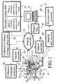
- a nuclear imaging system 10 includes a gamma camera 12.
- One or more detector heads 14, e.g. two heads in FIGURE 1 are mounted on robotic arms 16 that in turn mount to an overhead mechanical track 18, e.g. a ceiling track, that moves the robotic arms 16 and attached heads 14 linearly relative to a subject support 20.
- Each robotic arm 16 includes a plurality of joints 22 that provide a plurality of degrees of movement freedom for the attached head 14, such as rotation about an axis through the head, vertical motion, tomographic rotation about the subject support 20, and the like.
- each detector head 14 includes a scintillator and an array of photomultiplier tubes arranged to view the scintillator and detect optical flashes or scintillations resulting from impingement of radiation particles on the scintillator.
- photomultiplier tubes instead of photomultiplier tubes, photodiodes or other optical detectors can be used. Based upon the relative intensities detected by the various photomultiplier tubes during a radiation detection event, the location of the event on the two-dimensional surface of the detector head 14 is determined.
- a collimator 30 is arranged between the detector head 14 and a subject to be imaged.
- the collimator 30 is made of a radiation-absorbing material such as lead, and typically weighs between 100 pounds and 300 pounds.
- the collimator 30 includes an array of collimating bores, such that the collimator 30 is sometimes called a honeycomb collimator. Only radiation incident upon the collimator 30 within a narrow conical solid angle about the axis of each collimator bore passes through the collimator and reaches the detector face.
- Mechanical mountings formed into the collimator 30 and the detector head 14 detachably mount the collimator to the detector head.
- an automated collimator exchanger 34 is arranged to selectively mechanically switch collimators.
- Such automated collimator exchangers are known in the art, and a suitable automated collimator exchanger is described in U.S. Patent No. 5,519,223 issued to Hug, et al.
- the collimator exchanger 34 includes a collimator exchanger carrousel 36 corresponding to each detector head 14, which contains carriage segments (not shown) that hold collimators that can be detachably installed onto the head 14.
- a collimator transfer mechanism 38 removes a pair of collimators from the heads 14, retrieves a new collimator pair from the collimator exchanger carrousel 36, and installs the new collimator pair on the detector heads 14.
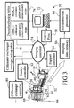
- a second nuclear imaging system embodiment 50 employs a gantry-based gamma camera 52.
- corresponding components of the imaging systems 10, 50 are designated with the same reference numbers, while new or substantially different components are assigned different reference numbers.
- a plurality of detector heads 54, (two heads in FIGURE 3 ) are arranged on a rotating gantry 56.
- the gantry rotationally positions or dynamically rotates the detector heads 54 relative to an examination region 58 within the interior of the gantry 56.
- each head 54 can be moved toward or away from the patient or tilted about an axis through the head 54.
- a subject support 60 is linearly movable into the examination region 58 to position an organ of interest within the field of view of the detectors 54, and to perform linear translation in planar or multi-slice tomographic scanning.
- An automated collimator exchanger 62 performs selected collimator changeouts.
- the collimator exchanger 62 includes a carrousel 64 with a plurality of shelves 66 containing collimators that can be detachably installed onto the heads 54.
- a collimator transfer mechanism 68 removes and installs collimators on the detector heads 54.
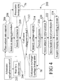
- a radiopharmaceutical administering means 70 is provided to administer a radiopharmaceutical to a subject in a step 202.
- the means 70 is an intravenous injector, e.g. a hypodermic needle.
- Other means for administering a radiopharmaceutical can be used instead, for example an intravenous drip or a rapid bolus intravenous injection, an orally administered substance such as a pill or a liquid medicine that contains the radiopharmaceutical, an inhaled radiopharmaceutical, an enema radiopharmaceutical administration, or the like.
- the radiopharmaceutical is typically administered a selected time interval prior to the imaging so as to permit the radiopharmaceutical to disperse into the subject and/or accumulate in the organ or organs of interest.
- the radiopharmaceutical is typically intravenously injected a selected two to four hours prior to the bone scan imaging session.
- the means 70 is optionally located remotely from the gamma camera 12, 52, and the subject transfers to the location of the gamma camera 12, 52 during the selected time delay imposed in a step 204.
- the subject is placed onto the support 20, 60 in a step 206, and is preferably stationarily affixed thereto by straps or other fasteners to minimize motion blurring in the subsequent imaging.
- the operator selects an imaging procedure in a step 208, preferably using a graphical user interface 72. Once the imaging procedure is selected it is implemented automatically by an imaging controller 74.
- the imaging controller 74 electronically accesses a procedures lookup table 76 and a collimator carriage lookup table 78.
- the procedures lookup table 76 includes parameters and other information pertaining to a wide range of imaging procedures.
- the lookup table 76 stores in electronic memory commonly used nuclear medical imaging procedures such as: various cardiac studies using ECT or planar imaging modalities with or without gating; total body planar scans such as bone scans; various spinal ECT scans; brain ECT scans; vertex brain ECT studies; brain PET scans; foot skeletal scans; GI bleed studies; renal flow and/or LPO/RPO scans; various planar lung scans including PET modalities; thyroid scans; and the like.
- the listed procedures are exemplary only.
- the procedures lookup table 76 is preferably modifiable such that parameters and recipes of selected imaging procedures can be periodically updated, and expandable such that additional imaging study procedures can be added or unused (e.g., obsolete) procedures deleted.
- the lookup table 76 includes information for setting up the gamma camera 12, 52 for that procedure.
- This information typically includes: a collimator selection (or a selection of no collimator, e.g. for molecular coincidence detection (MCD)); an initial subject position (e.g. table height and linear position); and initial detector head coordinates.
- MCD molecular coincidence detection
- suitable camera coordinates include a robotic arm/detector head position along the linear track, values for the joints 22 of the robotic arm 16, and a head proximity position relative to the subject.
- suitable camera coordinates include positions of the detector heads 54 on the gantry 56, the angular orientation of the gantry 56, a tilt or cant of each detector head 54; and a detector proximity position for each head 54 relative to the subject.
- the procedures lookup table 76 also contains a recipe describing the imaging sequence.
- the recipe includes information such as a detector head orbit path for tomographic imaging, a linear scan rate for planar imaging, selected head and/or subject support positions for step-and-shoot imaging, and the like.
- the collimator exchanger lookup table 78 identifies the contents of the collimator exchanger carrousel 36, 64. Each carriage segment 66 of the collimator exchanger carrousel 36, 64 holds a specific collimator that can be detachably installed onto the corresponding detector head 14, 54 by the collimator exchanger 34, 62. Identification and location information about the collimators is stored in the lookup table 78.
- the collimator exchanger lookup table 78 is preferably modifiable so that it can be updated as collimators are added, removed, or rearranged in the collimator exchanger carriage 36, 62.
- the collimator exchanger lookup table 78 identifies the collimator presently mounted on the detector heads 14, 54 and/or indicates that the carriage location 66 corresponding to the presently mounted collimator is empty. This information is updated at each collimator changeout.
- the heads 14, 54 include sensors that detect and identify the presently mounted collimator (or the lack of a mounted collimator, e.g. in a PET setup) then the collimator exchanger lookup table 78 optionally does not include information on the presently mounted collimator.
- the imaging controller 74 in a step 210 retrieves from the procedures lookup table 76 a collimator identification for the collimator appropriate for the procedure selected in the step 208.
- the imaging controller 74 determines whether a collimator changeout is needed. This determination is made by additionally identifying the presently mounted collimator, either by reading the collimator sensor of the gamma camera 14 or by accessing the collimator exchanger lookup table 78 if that table includes information on the presently mounted collimator.
- the imaging controller 74 accesses the collimator exchanger carriage lookup table 78 in a step 214 to identify a carriage segment that contains the collimator identified in the step 210.
- the imaging controller 74 directs a camera or gantry controller 82 to move the detector heads 14, 54 into a suitable position for the automated collimator exchange (step not shown).
- Information on the presently mounted collimator and the segment identification for the collimator selected in the step 210 is electronically forwarded from the imaging controller 74 to a collimator exchanger controller 80.
- the collimator exchanger controller 80 controls the collimator exchanger 34, 62, to automatically perform the collimator changeout with respect to the identified collimator segment in a step 216. If information on the presently mounted collimator is maintained in the collimator exchanger lookup table 78, that information is updated in the lookup table 78 to reflect the collimator changeout of the step 216.
- the imaging controller 74 electronically retrieves an initial position for the subject support 20, 60 from the procedures lookup table 76 contents for the selected procedure.
- the imaging controller 74 communicates the initial support position to a patient support controller 84 which moves the subject support 20, 60 to the initial position.
- This initial positioning involves a height adjustment and a linear movement of the table (in the embodiment of FIGURE 3 ) that preferably places the organ of interest within a field of view of the detector heads 14, 54.
- a typical detector head field of view spans about 15 inches. In constructed embodiments of the invention, it has been found that the field of view is wide enough so that calibration for variations in size between individual subjects is typically unnecessary, and so the procedures lookup table 76 stores an initial support position value that is generally applicable independent of the subject.
- the initial position is optionally indicated in the procedures lookup table 76 as an input parameter.
- the step 220 communicates with the graphical user interface 72 to ask for and receive an initial table position from the operator.
- An input parameter arrangement can also be used for other parameters which are advantageously supplied by the user, optionally along with a supplied default parameter.
- a step 222 the head coordinates are communicated to the gantry or camera controller 82.
- the controller 82 moves the detector heads 14, 54 via the overhead track 18, the robotic arms 16, the gantry 56, or other mechanical positioning element to place each gamma camera 14 at the retrieved initial coordinates.
- the robotic arms 16 and heads 14 are positioned near the organ of interest by the overhead track 18.
- the joints 22 of the robotic arms 16 are manipulated in accordance with the retrieved coordinates to place the detector heads 14 into a selected angular position and tilt or cant.
- the heads 14 are moved to a selected proximity to the patient.
- the heads 54 are moved on the gantry 56 and the gantry 56 is rotated to the retrieved gantry position such that the heads are positioned at selected angular orientations. Each head is tilted or canted to a retrieved tilt position. The heads 54 are moved to a selected proximity to the patient.
- the imaging procedure set-up steps 210, 212, 214, 216, 220, 222 occur automatically and in an optimal sequence responsive to the operator selecting the imaging procedure in the step 208.
- these set-up steps typically take about 5 minutes, as compared with set-up times of around 15 minutes or more for prior art manual and semi-annual workflows.
- the set-up steps 210, 212, 214, 216, 220, 222 are automated through electronic accessing of the lookup tables 76, 78 and preferably do not involve intervention of the operator. This frees the operator up to perform other tasks concurrently, such as positioning and administering to the patient, completing paperwork about the upcoming imaging procedure, reviewing patient medical records, or the like.
- the imaging controller 74 retrieves an imaging procedure recipe from the procedures lookup table 76.
- the recipe contains imaging sequence parameters such as a detector head orbit path for tomographic imaging (which can be a non-circular orbit), a scan rate for planar total body imaging, selected camera and/or subject support positions for step-and-shoot imaging, and the like, along with timing information therefor, which are implemented by the imaging controller 74 communicating with the gantry or camera controller 82 and the patient support controller 84.
- Such intermediate collimator changeouts are implemented by the imaging controller 74 via the collimator exchanger controller 80 which electronically accesses the collimator exchanger carriage lookup table 78 to identify suitable carriage segments for the exchange.
- Imaging data acquired during execution of the recipe in the step 224 is stored in an imaging data memory 86 and reconstructed by a reconstruction processor 88 to form an image representation.
- the reconstructed image representation is preferably displayed on the graphical user interface 72.
- the recipe includes instructions for returning the detector heads 14, 54 and the subject support 20, 60 to an idle position after the imaging procedure is completed.
- the nuclear camera imaging workflow 200 is readily adapted to performs a plurality of imaging procedures sequentially or in tandem. Those skilled in the art know that certain diagnostic nuclear medical imaging procedures are often performed in tandem. In one common tandem procedure, a total body scan is first performed, and then the operator selects regions in the total body scan that may be of clinical interest for further imaging using an ECT modality, a static planar imaging, or another procedure. The workflow 200 is readily adapted to perform such tandem procedures.
- an exemplary tandem imaging procedure 300 combines a total body bone scan with one or more subsequent selective static imaging procedures.
- a planar total body bone scan is performed over substantially the entire skeleton as described above.
- the total body planar imaging data is acquired in a step 302, e.g. according to the workflow 200.
- the bone scan data acquisition 302 occurs over an extended time period, e.g. around an hour or so.
- the imaging data is concurrently reconstructed 304 by the reconstruction processor 88 during the imaging 302 to generate an image 306 that is displayed on the graphical user interface 72.
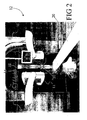
- the displayed image 306 starts as a partial image that grows in resolution. As the detector head moves, the partial images grows to create a whole body image.
- the operator typically notices particular areas which may be of clinical interest, such as areas with substantial accumulation of the radiopharmaceutical which may be indicative of bone break down or ongoing skeletal repair.
- the operator employs a pointing device 308 such as a touch screen or mouse pointer of the graphical user interface 72 to select one or more regions of interest, such as region 310 shown in FIGURE 5 .
- a region processor 90 converts the image coordinates designated by the pointing device into gamma camera or patient coordinates.
- the imaging controller 74 automatically retrieves 320 a designated static planar imaging procedure from the procedures lookup table 76, such as a close-up, magnified, or higher resolution imaging procedure.
- the imaging controller also retrieves the location on the patient from the region processor 90.
- the gamma camera 12, 52 is set-up 322 in accordance with the designated procedure along with subject position information from the pointing device 308.
- the collimator set-up steps 210, 212, 214, 216 are performed for the static imaging procedure as previously described.
- the subject support and detector head positioning steps 220, 222 are performed as described previously, except that the selected region of interest 310 is substituted by a region processor 90 (see FIGURES 1 and 3 ) for any default parameters stored in the procedures lookup table 76 that relate to arranging the detector heads 14, 54 relative to an area of the subject.
- Static planar imaging 324 is performed according to the designated procedure in a step 224 as described previously to acquire the static planar image at the region of interest 310.
- the retrieving 320, detector heads set-up 322, and static planar imaging 324 is repeated for each region of interest to obtain a plurality of static planar images.
- the operator can select a tomographic scanning procedure for one or more of the designated regions.
- tandem procedure described with reference to FIGURES 1 , 3 , 4 , and 5 significantly increases the imaging speed and reduces user intervention. It will also be appreciated that other tandem procedures can be similarly implemented, such as a tandem of a whole body or a static scan followed by tomographic imaging of selected regions of interest. Additionally, the region of interest can include other types of regions, such as axial, sagittal, or coronal slices, or volume regions of interest.
- imaging procedures have been described, it is further contemplated to further include quality control or other maintenance procedures in the lookup table 76.
- quality control or other maintenance procedures in the lookup table 76.
- nuclear medical imaging facilities typically perform daily quality control procedures using phantoms or other non-human subjects. These procedures are time consuming, and the set-up for each quality control or other maintenance procedure can involve switching of the collimators, and positioning of the detector heads 14, 54 and the subject support 20, 60 to selected initial positions.
- These maintenance procedures are also stored in the procedures lookup table 76.
- the operator merely selects the quality control procedure, e.g. according to the step 208 of FIGURE 6 . Responsive to the selection, the collimator changeout (if needed) and subject support and camera positioning is automatically performed according to the steps 210, 212, 214, 216, 220, 222 using parameters stored in the procedures lookup table 76. After these set-up steps, the quality control or other maintenance procedure is performed according to the step 224.
- the controllers 74, 80, 82, 84 and lookup tables 76, 78 can be physically constructed in a number of ways.
- a gantry personal computer (PC) 352 embodies the collimator exchanger controller 80, camera controller 82, and patient support controller 84 and electronically communicates with the gamma camera 12, while a separate acquisition PC 354 embodies the imaging controller 74, the region processor 90, and the graphical user interface 72.
- the gantry PC 352 performs software scripts that electronically access and control the motions and configurations of the detector heads 14, the patient support 20, and the collimator exchanger 34.
- the acquisition PC 354 constructs suitable software scripts corresponding to the procedure or procedures selected by the operator from the procedures lookup table 76, and electronically communicates the scripts to the gantry PC 352 for execution.
- the scripts are preferably encoded as interpretive scripts which do not require compilation prior to execution.
- the imaging data memory 86 is embodied as a storage device 356 such as one or more optical or magnetic disks or the like, and the reconstruction processor 88 is embodied on a separate reconstruction computer 358 which can be a PC, UNIX workstation, or the like.
- the storage device 356 is integrated with the reconstruction computer 358.
- the user controls substantially all aspects of a nuclear medical imaging procedure through the graphical user interface 72 of the acquisition PC 354, including the motions and configurations of the detector heads 14, movement of the patient support 20, and operation of the collimator exchanger 34. Furthermore, most of this control is automated by the procedures stored in the procedures lookup table 76 and the collimator exchanger information stored in the collimator exchanger carriage lookup table 78. These lookup tables are suitably stored in one or more non-volatile storage media of the computers 352, 354.
- a display terminal 360 located at or near the gamma camera 12 is preferably connected to the gantry PC 352. The operator can monitor and optionally manipulate camera operations in close proximity to the gamma camera 12 by directly interfacing with the gantry PC 352 via the terminal 360.
- the construction arrangement 350 is exemplary only. Those skilled in the art can readily construct other arrangements in which the controllers 74, 80, 82, 84 and lookup tables 76, 78, are embodied on a single computer or are distributed across a plurality of electronically communicating computers in a different arrangement from that shown in FIGURE 6 . Although discrete connections are shown between the computers 352, 354, 358, it is also contemplated to connect these computers via a network, for example using a dedicated network switch that interconnects the computers 352, 354, 358. In yet another variation, the reconstruction computer 358 can be replaced by a dedicated hardware reconstruction pipeline of application-specific integrated circuits (ASIC's).
- ASIC application-specific integrated circuits
Landscapes
- Physics & Mathematics (AREA)
- Health & Medical Sciences (AREA)
- Engineering & Computer Science (AREA)
- Biomedical Technology (AREA)
- General Health & Medical Sciences (AREA)
- Medical Informatics (AREA)
- Nuclear Medicine, Radiotherapy & Molecular Imaging (AREA)
- Optics & Photonics (AREA)
- Life Sciences & Earth Sciences (AREA)
- General Physics & Mathematics (AREA)
- High Energy & Nuclear Physics (AREA)
- Molecular Biology (AREA)
- Spectroscopy & Molecular Physics (AREA)
- Nuclear Medicine (AREA)
Claims (18)
- Verfahren zur Einstellung und Durchführung einer medizinischen Bildgebungssitzung eines Objekts unter Verwendung einer Gammakamera (12, 52), wobei das Verfahren (200) Folgendes umfasst:Auswählen (208) einer Bildgebungsprozedur an einem Eingabegerät (72),elektronisches Zugreifen (210) auf eine Prozedurtabelle (76), die für jede Prozedur Informationen zur Einstellung der Gammakamera (12) enthält, um die Identifikation eines Kollimators, der mit einem Detektorkopf (14, 54) in der ausgewählten Bildgebungsprozedur einzusetzen ist, und eine Anfangsabbildungsposition des Detektorkopfes (14, 54) für die ausgewählte Bildgebungsprozedur abzurufen,elektronisches Identifizieren (212) eines aktuell montierten Kollimators, der aktuell an dem Detektorkopf (14, 54) befestigt ist, undautomatisches Steuern des Einlegens (216) des am Detektorkopf (14, 54) zu verwendenden identifizierten Kollimators und der Positionierung (222) des Detektorkopfes an der identifizierten Anfangsabbildungsposition,wobei das Verfahren dadurch gekennzeichnet ist, dass es Folgendes umfasst:Erfassen (302) erster Bilddaten, die der ausgewählten Bildgebungsprozedur entsprechen,gleichzeitig mit dem Erfassen der ersten Bilddaten Bilden (304) einer Bilddarstellung,elektronisches Umwandeln der Bilddarstellung in eine vom Menschen lesbare Anzeige (306), die mit der Erfassung (302) der ersten Bilddaten wächst,elektronisches Eingeben (308) einer Angabe einer interessierenden Region (310) auf der vom Menschen lesbaren Anzeige (306),- als Reaktion auf die eingegebene Angabe der interessierenden Region (310) automatisches Neupositionieren (322) des Detektorkopfes (14, 54) hinsichtlich einer entsprechenden Region des Objekts undErfassen (324) von zweiten Bilddaten, wobei der Detektorkopf (14, 54) an der interessierenden Region positioniert ist.
- Verfahren nach Anspruch 1, das ferner Folgendes umfasst:elektronischen Zugreifen (214) auf eine Kollimatorwechslertabelle (78), um einen leeren Ort und einen Zielort zu identifizieren, der den ausgewählten Kollimator enthält, undelektronisches Übermitteln einer Identifikation des leeren und des Zielorts aus der Prozedurtabelle (76) zu einem automatischen Kollimatorwechsler (34, 62), der das Entfernen des aktuell montierten Kollimators und das Montieren des ausgewählten Kollimators vornimmt.
- Verfahren nach Anspruch 2, wobei der ausgewählte Kollimator kein Kollimator ist, da der Schritt (210) des elektronischen Zugreifens auf eine Kollimatorwechslertabelle das Entfernen des aktuell montierten Kollimators ohne Ersatz durch einen anderen Kollimator vornimmt.
- Verfahren nach einem der Ansprüche 1 bis 3, wobei die Identifikation der Anfangsposition des Detektorkopfes zumindest Folgendes enthält:entweder einen Anfangsdrehwinkel des Detektorkopfes (14, 54) odereine lineare Anfangsposition einer Patientenauflage (20, 60) odereine radiale Anfangsposition des Detektorkopfes (14, 54) odereine Anfangsneigung des Detektorkopfes (14, 54).
- Verfahren nach einem der Ansprüche 1 bis 4, das ferner Folgendes umfasst:elektronisches Zugreifen auf die Prozedurtabelle (76) zur Ermittlung eines Wertes für einen Parameter für die lineare Anfangsposition der Objektauflage (20, 60) undelektronisches Weiterleiten des Parameterwertes für die lineare Anfangsposition der Objektauflage (20, 60) von der Prozedurtabelle (76) zu einer Auflagensteuerung (84), die die Bewegung der Objektauflage (20, 60) zu einer linearen Position ausführt, die dem Parameterwert für die lineare Anfangsposition der Objektauflage (20, 60) entspricht.
- Verfahren nach Anspruch 1, wobei das Erfassen (302) von ersten Bilddaten Folgendes umfasst:Erfassen von planaren Bilddaten während der linearen Abtastung.
- Verfahren nach einem der Ansprüche 1 und 6, wobei das Erfassen (324) von zweiten Bilddaten das Erfassen von entwedera) statischen planaren Bilddaten, die die interessierende Region einschließen, oderb) tomographischen Daten der interessierenden Region umfasst.
- Verfahren nach einem der Ansprüche 1, 6 oder 7, das ferner nach dem Erfassen (302) von ersten Bilddaten, jedoch vor dem Erfassen (324) der zweiten Bilddaten Folgendes umfasst:elektronisches Zugreifen (320) auf die Prozedurtabelle (76) zur Ermittlung eines zweiten ausgewählten Kollimators zur Verwendung mit dem Detektorkopf (14, 54) bei der Erfassung (324) von zweiten Bilddaten undin Abhängigkeit davon, ob sich der ausgewählte Kollimator von dem zweiten ausgewählten Kollimator unterscheidet:elektronisches Abfragen (214) einer Kollimatorwechslertabelle (78) zur Ermittlung eines zweiten Zielorts, der den zweiten ausgewählten Kollimator enthält, undelektronisches Steuern (216) des Kollimatorwechslers (34, 62) mit dem ermittelten Ort, um ein Entfernen des ausgewählten Kollimators und eine Montage des zweiten ausgewählten Kollimators auszuführen.
- Nukleare Bildgebungsvorrichtung (10, 50) zur Abbildung eines Patienten, dem ein Radiopharmazeutikum verabreicht wurde (70), wobei die nukleare Bildgebungsvorrichtung (10, 50) Folgendes umfasst:eine Gammakamera (12, 52) mit zumindest einem Detektorkopf (14, 54),Prozedurauswahlmittel (72) zum Auswählen einer Abbildungsprozedur,Parameterabrufmittel (74) zum Abrufen von Parametern der ausgewählten Prozedur von einer Prozedur-Verweistabelle (76), die für jede Prozedur Informationen zur Einstellung der Gammakamera (12) enthält, wobei die Parameter eine Identifikation eines in der ausgewählten Abbildungsprozedur mit dem Detektorkopf (14, 54) zu verwendenden Kollimators und eine Anfangsabbildungsposition des Detektorkopfes (14, 54) für die ausgewählte Abbildungsprozedur beinhalten,Kollimatorwechselmittel (34, 62), die mit den Parameterabrufmitteln (74) zum Einlegen des am Detektorkopf (14, 54) zu verwendenden identifizierten Kollimators kommunizieren,Kamerapositionierungsmittel (82), die mit den Parameterabrufmitteln (74) zur Positionierung des Detektorkopfes (14, 54) an der Anfangsabbildungsposition kommunizieren, undRekonstruktionsmittel (88), die so konfiguriert sind, dass sie durch die Gammakamera (12, 52) erfasste Bilddaten in eine Bilddarstellung rekonstruieren, dadurch gekennzeichnet, dass die Rekonstruktionsmittel (88) so konfiguriert sind, dass sie die Bilddarstellung elektronisch in eine vom Menschen lesbare Anzeige (306) umwandeln, die mit der ersten Bilddatenerfassung (302) wächst,wobei die Prozedurauswahlmittel (72) Folgendes umfassen:Anzeigemittel (306) zum Anzeigen einer ersten von den Rekonstruktionsmitteln erzeugten ersten Bilddarstellung undRegionsauswahlmittel (308) für die Benutzerauswahl einer interessierenden Region (310) in der Bilddarstellung, wobei als Reaktion auf die Benutzerauswahl einer interessierenden Region (310) die Prozedurauswahlmittel (72) eine zweite Prozedur zur Abbildung der interessierenden Region (310) auswählen.
- Nukleare Bildgebungsvorrichtung (50) nach Anspruch 9, wobei die Kamerapositionierungsmittel (82) Folgendes umfassen:eine rotierende Gantry (56), an der zumindest ein Detektorkopf (54) montiert ist.
- Nukleare Bildgebungsvorrichtung (10) nach Anspruch 9, wobei die Kamerapositionierungsmittel (82) Folgendes umfassen:eine lineare Deckenlaufbahn (18), die den Detektorkopf (14) in eine erste lineare Richtung bewegt, undeinen Roboterarm (16) für jeden Detektorkopf (14), dessen erstes Ende mit der Deckenlaufbahn (18) und dessen zweites Ende mit dem Detektorkopf (14) verbunden ist, wobei der Roboterarm (16) über eine Vielzahl von Freiheitsgraden für die Positionierung des mit ihm verbundenen Detektorkopfes (14) verfügt.
- Nukleare Bildgebungsvorrichtung (10, 50) nach einem der Ansprüche 9 bis 11, die ferner Folgendes umfasst:Kollimator-Verweismittel (78) zur Identifizierung von Kollimatoren, die in einem Kollimatorschlitten der Kollimatorwechselmittel (34, 62) gelagert sind, wobei die Kollimatorwechselmittel (34, 62) die Kollimator-Verweismittel (78) referenzieren, um den Ort eines der Kollimatoridentifikation entsprechenden Kollimators auszuwählen.
- Nukleare Bildgebungsvorrichtung (10, 50) nach einem der Ansprüche 9 bis 12, die ferner Folgendes umfasst:Objektauflagemittel (20, 60) zum Abstützen des Objekts in Bezug auf die Gammakamera (12, 52).
- Nukleare Bildgebungsvorrichtung (10, 50) nach Anspruch 13, wobei die Prozedurauswahlmittel (72) eine Abbildungsprozedur aus einer Gruppe auswählen, die Folgendes umfasst:eine Computertomographie-Rezeptur, die den Detektorkopf (14, 54) während der Erfassung von Bilddaten in einer ausgewählten Kreisbahn um den Patienten dreht,eine Rezeptur zur planaren Abtastung, die Bilddaten erfasst, während entweder die Patientenauflagemittel (20, 60) oder der Detektorkopf (14, 54) bewegt wird, um eine lineare Bewegung des Detektorkopfes (14, 54) in Bezug auf den Patienten auszuführen, undeine Rezeptur zur statischen Abtastung, die Bilddaten erfasst, während der Detektorkopf (14, 54) an abgerufenen Koordinaten verbleibt und die Patientenauflagemittel (20, 60) an abgerufenen Positionskoordinaten für die Patientenauflage verbleiben.
- Nukleare Bildgebungsvorrichtung (10, 50) nach einem der Ansprüche 9 bis 14, wobei die Prozedurauswahlmittel (72) eine Qualitätskontrollrezeptur für die Lenkung einer Qualitätskontrollprozedur auswählen.
- Nukleare Bildgebungsvorrichtung (10, 50) nach einem der Ansprüche 9 bis 15, wobei die Parameterabrufmittel (74) Folgendes umfassen:einen Erfassungscomputer (354), der eine vorher aufgezeichnete Rezeptur und Parameter für die Konfiguration der Gammakamera (12, 52) abruft, die der ausgewählten Abbildungsprozedur entsprechen, und elektronisch Befehle an zumindest entweder die Kamerapositionierungsmittel (82) oder die Kollimatorwechselmittel (34, 62) weiterleitet.
- Nukleare Bildgebungsvorrichtung (10, 50) nach Anspruch 16, wobei die Kamerapositionierungsmittel (82) Folgendes umfassen:einen Gantry-PC (352), der ein von dem Erfassungscomputer empfangenes Software-Skript ausführt, um die ausgewählte Abbildungsprozedur einschließlich der Bewegung des Detektorkopfes (14, 54) in eine Anfangsabbildungsposition auszuführen.
- Nukleare Bildgebungsvorrichtung (10, 50) nach einem der Ansprüche 16 und 17, wobei der Erfassungscomputer (354) ferner die Prozedurauswahlmittel (72) umfasst und ein entsprechender Bediener eine Abbildungsprozedur unter Verwendung des Erfassungscomputers (354) auswählt und die ausgewählte Abbildungsprozedur ohne direkten Zugriff auf die Kamerapositionierungsmittel (82, 352) ausführt.
Applications Claiming Priority (3)
| Application Number | Priority Date | Filing Date | Title |
|---|---|---|---|
| US167833 | 1999-11-29 | ||
| US10/167,833 US6906328B2 (en) | 2002-06-12 | 2002-06-12 | Gamma camera workflow automation |
| PCT/IB2003/002183 WO2003107038A1 (en) | 2002-06-12 | 2003-06-09 | Automation of the workflow of a gamma camera |
Publications (2)
| Publication Number | Publication Date |
|---|---|
| EP1516205A1 EP1516205A1 (de) | 2005-03-23 |
| EP1516205B1 true EP1516205B1 (de) | 2014-03-12 |
Family
ID=29732267
Family Applications (1)
| Application Number | Title | Priority Date | Filing Date |
|---|---|---|---|
| EP03735863.7A Expired - Lifetime EP1516205B1 (de) | 2002-06-12 | 2003-06-09 | Automatisieren der arbeitsflussverwaltung einer gamma-kamera |
Country Status (6)
| Country | Link |
|---|---|
| US (1) | US6906328B2 (de) |
| EP (1) | EP1516205B1 (de) |
| JP (1) | JP4633460B2 (de) |
| CN (1) | CN100339722C (de) |
| AU (1) | AU2003236946A1 (de) |
| WO (1) | WO2003107038A1 (de) |
Families Citing this family (25)
| Publication number | Priority date | Publication date | Assignee | Title |
|---|---|---|---|---|
| US6809321B2 (en) * | 2002-07-30 | 2004-10-26 | Siemens Medical Solutions Usa, Inc. | Dynamically optimized coincidence septa |
| US7580508B2 (en) * | 2003-09-26 | 2009-08-25 | Siemens Medical Solutions, Usa, Inc. | Integrated collimator handling system and method |
| US8173966B2 (en) * | 2004-06-28 | 2012-05-08 | Siemens Medical Solutions Usa, Inc. | Collimator storage apparatus integrated with patient support |
| US7335888B2 (en) * | 2004-09-24 | 2008-02-26 | Siemens Medical Solutions Usa, Inc. | Imaging apparatus to acquire tomography projections with improved orbit |
| WO2006037087A2 (en) * | 2004-09-27 | 2006-04-06 | Digirad Corporation | Pre-acquisition identification of region for image acquisition time optimization for radiation imaging systems |
| CN101176016B (zh) * | 2005-05-13 | 2013-07-31 | 皇家飞利浦电子股份有限公司 | 用于核医疗的多罩体探测器 |
| WO2007023401A1 (en) * | 2005-08-26 | 2007-03-01 | Koninklijke Philips Electronics, N.V. | High resolution medical imaging detector |
| US10463252B2 (en) * | 2007-03-27 | 2019-11-05 | Siemens Medical Solutions Usa, Inc. | Interface for component identification, communication and power supply between interchangeable system components |
| US7986988B2 (en) * | 2007-09-27 | 2011-07-26 | Siemens Medical Solutions Usa, Inc. | Reference height calibration scheme for modular multi-modality medical imaging system |
| US7954996B2 (en) * | 2008-07-08 | 2011-06-07 | General Electric Company | Positioning system with tilting arm support for imaging devices |
| JP5413019B2 (ja) * | 2009-07-27 | 2014-02-12 | 大日本印刷株式会社 | 放射線画像処理装置、放射線画像処理方法及び放射線画像処理プログラム |
| WO2011038236A2 (en) * | 2009-09-25 | 2011-03-31 | Ortho Kinematics, Inc. | Systems and devices for an integrated imaging system with real-time feedback loops and methods therefor |
| US8455834B2 (en) * | 2009-12-02 | 2013-06-04 | General Electric Company | Systems and methods for patient positioning for nuclear medicine imaging |
| GB2477347A (en) * | 2010-02-01 | 2011-08-03 | Cambridge Entpr Ltd | A Hand Operated Controller |
| US20120039537A1 (en) * | 2010-08-10 | 2012-02-16 | Keys Gregory C | Method, apparatus, and system for workflow participation of an imaging device |
| US8675820B2 (en) * | 2010-08-10 | 2014-03-18 | Varian Medical Systems, Inc. | Electronic conical collimator verification |
| EP2729084A4 (de) * | 2011-07-07 | 2015-03-04 | Olympus Corp | Medizinischer master-slave- manipulator |
| JP5800616B2 (ja) * | 2011-07-15 | 2015-10-28 | オリンパス株式会社 | マニピュレータシステム |
| US9066669B2 (en) | 2012-10-08 | 2015-06-30 | Elekta Ab (Publ) | Apparatus and methods for fitting attachments |
| KR20150040768A (ko) | 2013-10-07 | 2015-04-15 | 삼성전자주식회사 | 엑스선 장치 및 엑스선 디텍터 |
| US9349495B2 (en) * | 2014-04-22 | 2016-05-24 | General Electric Company | Systems and methods for improved collimation sensitivity |
| CN103942840A (zh) * | 2014-05-15 | 2014-07-23 | 四川材料与工艺研究所 | 一种利用γ相机拍摄二维图像重构放射性物质三维分布的方法 |
| DE102016211720A1 (de) * | 2016-06-29 | 2018-01-04 | Siemens Healthcare Gmbh | Verfahren zum Positionieren eines positionierbaren Tisches |
| NL2022409B1 (en) * | 2019-01-17 | 2020-08-18 | Milabs Bv | Multimodal imaging system |
| CN116077077B (zh) * | 2021-11-08 | 2026-02-27 | 上海联影医疗科技股份有限公司 | 准直器安装方法、装置、系统及装载设备 |
Family Cites Families (12)
| Publication number | Priority date | Publication date | Assignee | Title |
|---|---|---|---|---|
| JPS5654796A (en) * | 1979-10-12 | 1981-05-14 | Toshiba Corp | X-ray diagnosing device |
| JPS6388769U (de) * | 1986-11-28 | 1988-06-09 | ||
| JPH04168393A (ja) * | 1990-10-31 | 1992-06-16 | Shimadzu Corp | リング型spect装置 |
| US5519223A (en) * | 1994-03-03 | 1996-05-21 | Adac Laboratories, Inc. | Apparatus and method for automated collimator exchange |
| EP0871902B1 (de) * | 1994-12-23 | 2005-06-15 | Digirad Corporation | Halbleiter-gammastrahlungskamera und medizinisches bildgebungssystem |
| JP3604491B2 (ja) * | 1996-02-29 | 2004-12-22 | 株式会社東芝 | ガンマカメラ装置 |
| JPH09264962A (ja) * | 1996-03-27 | 1997-10-07 | Hitachi Medical Corp | シンチレーションカメラにおけるイメージ収集方法 |
| US6140649A (en) * | 1997-12-23 | 2000-10-31 | General Electric Company | Imaging attenuation correction employing simultaneous transmission/emission scanning |
| US6177675B1 (en) * | 1998-04-22 | 2001-01-23 | Picker International, Inc. | Gamma camera system having multi-resolution detectors |
| CA2350648A1 (en) * | 1998-11-20 | 2000-06-02 | Direct Radiography Corporation | Interactive digital radiographic system |
| US6590214B1 (en) * | 1999-01-26 | 2003-07-08 | Koninklijke Philips Electronics N.V. | Collimator exchange system |
| US6441377B1 (en) * | 1999-11-23 | 2002-08-27 | Koninklijke Philips Electronics N.V. | System for exchanging and storing collimators for medical imaging devices |
-
2002
- 2002-06-12 US US10/167,833 patent/US6906328B2/en not_active Expired - Lifetime
-
2003
- 2003-06-09 AU AU2003236946A patent/AU2003236946A1/en not_active Abandoned
- 2003-06-09 CN CNB038137054A patent/CN100339722C/zh not_active Expired - Lifetime
- 2003-06-09 JP JP2004513801A patent/JP4633460B2/ja not_active Expired - Lifetime
- 2003-06-09 EP EP03735863.7A patent/EP1516205B1/de not_active Expired - Lifetime
- 2003-06-09 WO PCT/IB2003/002183 patent/WO2003107038A1/en not_active Ceased
Also Published As
| Publication number | Publication date |
|---|---|
| US20030230723A1 (en) | 2003-12-18 |
| WO2003107038A1 (en) | 2003-12-24 |
| AU2003236946A1 (en) | 2003-12-31 |
| CN1659448A (zh) | 2005-08-24 |
| JP2005529349A (ja) | 2005-09-29 |
| EP1516205A1 (de) | 2005-03-23 |
| US6906328B2 (en) | 2005-06-14 |
| CN100339722C (zh) | 2007-09-26 |
| JP4633460B2 (ja) | 2011-02-16 |
Similar Documents
| Publication | Publication Date | Title |
|---|---|---|
| EP1516205B1 (de) | Automatisieren der arbeitsflussverwaltung einer gamma-kamera | |
| US10209376B2 (en) | Systems for image detection | |
| EP0953942B1 (de) | Computertomograph | |
| JP5155304B2 (ja) | 撮像基準の幾何解析に基づく、4次元ctの呼吸位相への遡及的ソーティング | |
| US7720518B2 (en) | Nuclear medical diagnostic equipment and data acquisition method for nuclear medical diagnosis | |
| JP4782680B2 (ja) | Pet−ctシステムにおける較正画像アライメント装置及び方法 | |
| US9297913B2 (en) | Imaging system and method overcoming obstructions using independently controllable detectors | |
| CN101534713A (zh) | 集成医疗成像系统 | |
| JPH07194592A (ja) | X線コンピュータ断層撮影装置 | |
| CN111465349A (zh) | 具有可变换的任务优化几何结构的正电子发射断层摄影(pet)系统 | |
| WO2013027228A1 (en) | Tool positioning system | |
| US6603991B1 (en) | Method and apparatus for dual mode medical imaging system | |
| JP2004230154A (ja) | 多数の検出器パネルを利用した空間測定ctシステム及び方法 | |
| US20070053486A1 (en) | Methods and apparatus for nuclear tomo-cardiology scanning | |
| JP3810019B2 (ja) | 画像撮影装置 | |
| Van Laere et al. | Transfer of normal 99mTc-ECD brain SPET databases between different gamma cameras | |
| JP2004037418A (ja) | 核医学診断装置 | |
| EP1733682A2 (de) | Bildaufnahmesteuerung für eine Röntgen-CT-Vorrichtung | |
| JPWO2017022495A1 (ja) | 医用画像診断装置及びその制御方法 | |
| JP2004045318A (ja) | 核医学診断装置 | |
| JP4169291B2 (ja) | 核医学診断装置 | |
| JPH0619438B2 (ja) | エミッションct装置 | |
| JPS6053135A (ja) | 核磁気共鳴映像装置 |
Legal Events
| Date | Code | Title | Description |
|---|---|---|---|
| PUAI | Public reference made under article 153(3) epc to a published international application that has entered the european phase |
Free format text: ORIGINAL CODE: 0009012 |
|
| 17P | Request for examination filed |
Effective date: 20050112 |
|
| AK | Designated contracting states |
Kind code of ref document: A1 Designated state(s): AT BE BG CH CY CZ DE DK EE ES FI FR GB GR HU IE IT LI LU MC NL PT RO SE SI SK TR |
|
| AX | Request for extension of the european patent |
Extension state: AL LT LV MK |
|
| DAX | Request for extension of the european patent (deleted) | ||
| 17Q | First examination report despatched |
Effective date: 20101206 |
|
| RAP1 | Party data changed (applicant data changed or rights of an application transferred) |
Owner name: KONINKLIJKE PHILIPS N.V. |
|
| GRAP | Despatch of communication of intention to grant a patent |
Free format text: ORIGINAL CODE: EPIDOSNIGR1 |
|
| INTG | Intention to grant announced |
Effective date: 20131008 |
|
| GRAS | Grant fee paid |
Free format text: ORIGINAL CODE: EPIDOSNIGR3 |
|
| GRAA | (expected) grant |
Free format text: ORIGINAL CODE: 0009210 |
|
| AK | Designated contracting states |
Kind code of ref document: B1 Designated state(s): AT BE BG CH CY CZ DE DK EE ES FI FR GB GR HU IE IT LI LU MC NL PT RO SE SI SK TR |
|
| REG | Reference to a national code |
Ref country code: GB Ref legal event code: FG4D |
|
| REG | Reference to a national code |
Ref country code: CH Ref legal event code: EP |
|
| REG | Reference to a national code |
Ref country code: AT Ref legal event code: REF Ref document number: 656660 Country of ref document: AT Kind code of ref document: T Effective date: 20140315 |
|
| REG | Reference to a national code |
Ref country code: IE Ref legal event code: FG4D |
|
| REG | Reference to a national code |
Ref country code: DE Ref legal event code: R096 Ref document number: 60345846 Country of ref document: DE Effective date: 20140424 |
|
| REG | Reference to a national code |
Ref country code: NL Ref legal event code: VDEP Effective date: 20140312 |
|
| REG | Reference to a national code |
Ref country code: AT Ref legal event code: MK05 Ref document number: 656660 Country of ref document: AT Kind code of ref document: T Effective date: 20140312 |
|
| PG25 | Lapsed in a contracting state [announced via postgrant information from national office to epo] |
Ref country code: FI Free format text: LAPSE BECAUSE OF FAILURE TO SUBMIT A TRANSLATION OF THE DESCRIPTION OR TO PAY THE FEE WITHIN THE PRESCRIBED TIME-LIMIT Effective date: 20140312 Ref country code: SE Free format text: LAPSE BECAUSE OF FAILURE TO SUBMIT A TRANSLATION OF THE DESCRIPTION OR TO PAY THE FEE WITHIN THE PRESCRIBED TIME-LIMIT Effective date: 20140312 Ref country code: CY Free format text: LAPSE BECAUSE OF FAILURE TO SUBMIT A TRANSLATION OF THE DESCRIPTION OR TO PAY THE FEE WITHIN THE PRESCRIBED TIME-LIMIT Effective date: 20140312 |
|
| PG25 | Lapsed in a contracting state [announced via postgrant information from national office to epo] |
Ref country code: RO Free format text: LAPSE BECAUSE OF FAILURE TO SUBMIT A TRANSLATION OF THE DESCRIPTION OR TO PAY THE FEE WITHIN THE PRESCRIBED TIME-LIMIT Effective date: 20140312 Ref country code: NL Free format text: LAPSE BECAUSE OF FAILURE TO SUBMIT A TRANSLATION OF THE DESCRIPTION OR TO PAY THE FEE WITHIN THE PRESCRIBED TIME-LIMIT Effective date: 20140312 Ref country code: BG Free format text: LAPSE BECAUSE OF FAILURE TO SUBMIT A TRANSLATION OF THE DESCRIPTION OR TO PAY THE FEE WITHIN THE PRESCRIBED TIME-LIMIT Effective date: 20140612 Ref country code: BE Free format text: LAPSE BECAUSE OF FAILURE TO SUBMIT A TRANSLATION OF THE DESCRIPTION OR TO PAY THE FEE WITHIN THE PRESCRIBED TIME-LIMIT Effective date: 20140312 Ref country code: EE Free format text: LAPSE BECAUSE OF FAILURE TO SUBMIT A TRANSLATION OF THE DESCRIPTION OR TO PAY THE FEE WITHIN THE PRESCRIBED TIME-LIMIT Effective date: 20140312 Ref country code: CZ Free format text: LAPSE BECAUSE OF FAILURE TO SUBMIT A TRANSLATION OF THE DESCRIPTION OR TO PAY THE FEE WITHIN THE PRESCRIBED TIME-LIMIT Effective date: 20140312 |
|
| PG25 | Lapsed in a contracting state [announced via postgrant information from national office to epo] |
Ref country code: ES Free format text: LAPSE BECAUSE OF FAILURE TO SUBMIT A TRANSLATION OF THE DESCRIPTION OR TO PAY THE FEE WITHIN THE PRESCRIBED TIME-LIMIT Effective date: 20140312 Ref country code: AT Free format text: LAPSE BECAUSE OF FAILURE TO SUBMIT A TRANSLATION OF THE DESCRIPTION OR TO PAY THE FEE WITHIN THE PRESCRIBED TIME-LIMIT Effective date: 20140312 Ref country code: SK Free format text: LAPSE BECAUSE OF FAILURE TO SUBMIT A TRANSLATION OF THE DESCRIPTION OR TO PAY THE FEE WITHIN THE PRESCRIBED TIME-LIMIT Effective date: 20140312 |
|
| REG | Reference to a national code |
Ref country code: DE Ref legal event code: R097 Ref document number: 60345846 Country of ref document: DE |
|
| PG25 | Lapsed in a contracting state [announced via postgrant information from national office to epo] |
Ref country code: PT Free format text: LAPSE BECAUSE OF FAILURE TO SUBMIT A TRANSLATION OF THE DESCRIPTION OR TO PAY THE FEE WITHIN THE PRESCRIBED TIME-LIMIT Effective date: 20140714 |
|
| PLBE | No opposition filed within time limit |
Free format text: ORIGINAL CODE: 0009261 |
|
| STAA | Information on the status of an ep patent application or granted ep patent |
Free format text: STATUS: NO OPPOSITION FILED WITHIN TIME LIMIT |
|
| PG25 | Lapsed in a contracting state [announced via postgrant information from national office to epo] |
Ref country code: LU Free format text: LAPSE BECAUSE OF FAILURE TO SUBMIT A TRANSLATION OF THE DESCRIPTION OR TO PAY THE FEE WITHIN THE PRESCRIBED TIME-LIMIT Effective date: 20140609 Ref country code: MC Free format text: LAPSE BECAUSE OF FAILURE TO SUBMIT A TRANSLATION OF THE DESCRIPTION OR TO PAY THE FEE WITHIN THE PRESCRIBED TIME-LIMIT Effective date: 20140312 Ref country code: DK Free format text: LAPSE BECAUSE OF FAILURE TO SUBMIT A TRANSLATION OF THE DESCRIPTION OR TO PAY THE FEE WITHIN THE PRESCRIBED TIME-LIMIT Effective date: 20140312 |
|
| REG | Reference to a national code |
Ref country code: CH Ref legal event code: PL |
|
| 26N | No opposition filed |
Effective date: 20141215 |
|
| GBPC | Gb: european patent ceased through non-payment of renewal fee |
Effective date: 20140612 |
|
| REG | Reference to a national code |
Ref country code: IE Ref legal event code: MM4A |
|
| REG | Reference to a national code |
Ref country code: DE Ref legal event code: R097 Ref document number: 60345846 Country of ref document: DE Effective date: 20141215 |
|
| REG | Reference to a national code |
Ref country code: FR Ref legal event code: ST Effective date: 20150227 |
|
| PG25 | Lapsed in a contracting state [announced via postgrant information from national office to epo] |
Ref country code: IT Free format text: LAPSE BECAUSE OF FAILURE TO SUBMIT A TRANSLATION OF THE DESCRIPTION OR TO PAY THE FEE WITHIN THE PRESCRIBED TIME-LIMIT Effective date: 20140312 |
|
| PG25 | Lapsed in a contracting state [announced via postgrant information from national office to epo] |
Ref country code: CH Free format text: LAPSE BECAUSE OF NON-PAYMENT OF DUE FEES Effective date: 20140630 Ref country code: LI Free format text: LAPSE BECAUSE OF NON-PAYMENT OF DUE FEES Effective date: 20140630 Ref country code: IE Free format text: LAPSE BECAUSE OF NON-PAYMENT OF DUE FEES Effective date: 20140609 |
|
| PG25 | Lapsed in a contracting state [announced via postgrant information from national office to epo] |
Ref country code: FR Free format text: LAPSE BECAUSE OF NON-PAYMENT OF DUE FEES Effective date: 20140630 Ref country code: GB Free format text: LAPSE BECAUSE OF NON-PAYMENT OF DUE FEES Effective date: 20140612 |
|
| PG25 | Lapsed in a contracting state [announced via postgrant information from national office to epo] |
Ref country code: SI Free format text: LAPSE BECAUSE OF FAILURE TO SUBMIT A TRANSLATION OF THE DESCRIPTION OR TO PAY THE FEE WITHIN THE PRESCRIBED TIME-LIMIT Effective date: 20140312 |
|
| PGFP | Annual fee paid to national office [announced via postgrant information from national office to epo] |
Ref country code: TR Payment date: 20150603 Year of fee payment: 13 |
|
| PG25 | Lapsed in a contracting state [announced via postgrant information from national office to epo] |
Ref country code: GR Free format text: LAPSE BECAUSE OF FAILURE TO SUBMIT A TRANSLATION OF THE DESCRIPTION OR TO PAY THE FEE WITHIN THE PRESCRIBED TIME-LIMIT Effective date: 20140613 |
|
| PG25 | Lapsed in a contracting state [announced via postgrant information from national office to epo] |
Ref country code: HU Free format text: LAPSE BECAUSE OF FAILURE TO SUBMIT A TRANSLATION OF THE DESCRIPTION OR TO PAY THE FEE WITHIN THE PRESCRIBED TIME-LIMIT; INVALID AB INITIO Effective date: 20030609 |
|
| PGFP | Annual fee paid to national office [announced via postgrant information from national office to epo] |
Ref country code: DE Payment date: 20210628 Year of fee payment: 19 |
|
| PG25 | Lapsed in a contracting state [announced via postgrant information from national office to epo] |
Ref country code: TR Free format text: LAPSE BECAUSE OF NON-PAYMENT OF DUE FEES Effective date: 20160609 |
|
| REG | Reference to a national code |
Ref country code: DE Ref legal event code: R119 Ref document number: 60345846 Country of ref document: DE |
|
| PG25 | Lapsed in a contracting state [announced via postgrant information from national office to epo] |
Ref country code: DE Free format text: LAPSE BECAUSE OF NON-PAYMENT OF DUE FEES Effective date: 20230103 |