EP1516178B1 - Verfahren zur Ultraschallkontrolle von Schweissverbindungen - Google Patents
Verfahren zur Ultraschallkontrolle von Schweissverbindungen Download PDFInfo
- Publication number
- EP1516178B1 EP1516178B1 EP03760034.3A EP03760034A EP1516178B1 EP 1516178 B1 EP1516178 B1 EP 1516178B1 EP 03760034 A EP03760034 A EP 03760034A EP 1516178 B1 EP1516178 B1 EP 1516178B1
- Authority
- EP
- European Patent Office
- Prior art keywords
- joint
- translators
- translator
- controlled
- ultrasonic
- Prior art date
- Legal status (The legal status is an assumption and is not a legal conclusion. Google has not performed a legal analysis and makes no representation as to the accuracy of the status listed.)
- Expired - Lifetime
Links
Images


Classifications
-
- G—PHYSICS
- G01—MEASURING; TESTING
- G01N—INVESTIGATING OR ANALYSING MATERIALS BY DETERMINING THEIR CHEMICAL OR PHYSICAL PROPERTIES
- G01N29/00—Investigating or analysing materials by the use of ultrasonic, sonic or infrasonic waves; Visualisation of the interior of objects by transmitting ultrasonic or sonic waves through the object
- G01N29/34—Generating the ultrasonic, sonic or infrasonic waves, e.g. electronic circuits specially adapted therefor
- G01N29/348—Generating the ultrasonic, sonic or infrasonic waves, e.g. electronic circuits specially adapted therefor with frequency characteristics, e.g. single frequency signals, chirp signals
-
- B—PERFORMING OPERATIONS; TRANSPORTING
- B23—MACHINE TOOLS; METAL-WORKING NOT OTHERWISE PROVIDED FOR
- B23K—SOLDERING OR UNSOLDERING; WELDING; CLADDING OR PLATING BY SOLDERING OR WELDING; CUTTING BY APPLYING HEAT LOCALLY, e.g. FLAME CUTTING; WORKING BY LASER BEAM
- B23K31/00—Processes relevant to this subclass, specially adapted for particular articles or purposes, but not covered by any single one of main groups B23K1/00 - B23K28/00
- B23K31/12—Processes relevant to this subclass, specially adapted for particular articles or purposes, but not covered by any single one of main groups B23K1/00 - B23K28/00 relating to investigating the properties, e.g. the weldability, of materials
-
- G—PHYSICS
- G01—MEASURING; TESTING
- G01N—INVESTIGATING OR ANALYSING MATERIALS BY DETERMINING THEIR CHEMICAL OR PHYSICAL PROPERTIES
- G01N29/00—Investigating or analysing materials by the use of ultrasonic, sonic or infrasonic waves; Visualisation of the interior of objects by transmitting ultrasonic or sonic waves through the object
- G01N29/04—Analysing solids
- G01N29/043—Analysing solids in the interior, e.g. by shear waves
-
- G—PHYSICS
- G01—MEASURING; TESTING
- G01N—INVESTIGATING OR ANALYSING MATERIALS BY DETERMINING THEIR CHEMICAL OR PHYSICAL PROPERTIES
- G01N29/00—Investigating or analysing materials by the use of ultrasonic, sonic or infrasonic waves; Visualisation of the interior of objects by transmitting ultrasonic or sonic waves through the object
- G01N29/04—Analysing solids
- G01N29/06—Visualisation of the interior, e.g. acoustic microscopy
- G01N29/0609—Display arrangements, e.g. colour displays
- G01N29/0645—Display representation or displayed parameters, e.g. A-, B- or C-Scan
-
- G—PHYSICS
- G01—MEASURING; TESTING
- G01N—INVESTIGATING OR ANALYSING MATERIALS BY DETERMINING THEIR CHEMICAL OR PHYSICAL PROPERTIES
- G01N29/00—Investigating or analysing materials by the use of ultrasonic, sonic or infrasonic waves; Visualisation of the interior of objects by transmitting ultrasonic or sonic waves through the object
- G01N29/04—Analysing solids
- G01N29/06—Visualisation of the interior, e.g. acoustic microscopy
- G01N29/0654—Imaging
- G01N29/069—Defect imaging, localisation and sizing using, e.g. time of flight diffraction [TOFD], synthetic aperture focusing technique [SAFT], Amplituden-Laufzeit-Ortskurven [ALOK] technique
-
- G—PHYSICS
- G01—MEASURING; TESTING
- G01N—INVESTIGATING OR ANALYSING MATERIALS BY DETERMINING THEIR CHEMICAL OR PHYSICAL PROPERTIES
- G01N2291/00—Indexing codes associated with group G01N29/00
- G01N2291/01—Indexing codes associated with the measuring variable
- G01N2291/011—Velocity or travel time
-
- G—PHYSICS
- G01—MEASURING; TESTING
- G01N—INVESTIGATING OR ANALYSING MATERIALS BY DETERMINING THEIR CHEMICAL OR PHYSICAL PROPERTIES
- G01N2291/00—Indexing codes associated with group G01N29/00
- G01N2291/04—Wave modes and trajectories
- G01N2291/042—Wave modes
- G01N2291/0421—Longitudinal waves
-
- G—PHYSICS
- G01—MEASURING; TESTING
- G01N—INVESTIGATING OR ANALYSING MATERIALS BY DETERMINING THEIR CHEMICAL OR PHYSICAL PROPERTIES
- G01N2291/00—Indexing codes associated with group G01N29/00
- G01N2291/04—Wave modes and trajectories
- G01N2291/042—Wave modes
- G01N2291/0422—Shear waves, transverse waves, horizontally polarised waves
-
- G—PHYSICS
- G01—MEASURING; TESTING
- G01N—INVESTIGATING OR ANALYSING MATERIALS BY DETERMINING THEIR CHEMICAL OR PHYSICAL PROPERTIES
- G01N2291/00—Indexing codes associated with group G01N29/00
- G01N2291/04—Wave modes and trajectories
- G01N2291/044—Internal reflections (echoes), e.g. on walls or defects
-
- G—PHYSICS
- G01—MEASURING; TESTING
- G01N—INVESTIGATING OR ANALYSING MATERIALS BY DETERMINING THEIR CHEMICAL OR PHYSICAL PROPERTIES
- G01N2291/00—Indexing codes associated with group G01N29/00
- G01N2291/10—Number of transducers
- G01N2291/102—Number of transducers one emitter, one receiver
-
- G—PHYSICS
- G01—MEASURING; TESTING
- G01N—INVESTIGATING OR ANALYSING MATERIALS BY DETERMINING THEIR CHEMICAL OR PHYSICAL PROPERTIES
- G01N2291/00—Indexing codes associated with group G01N29/00
- G01N2291/26—Scanned objects
- G01N2291/267—Welds
- G01N2291/2675—Seam, butt welding
Definitions
- the present invention relates to a method for the non-destructive ultrasonic testing of materials and, more particularly, welded joints joining, end to end, two metal parts, in particular of the plate or sheet type.
- This method allows the control, in manufacture and in service, of structures and equipment with welded joints, for example obtained by local melting, and may be the seat of flat defects like crack or volume defects; in this respect, the terms "defect” or "crack” will be used interchangeably.
- the method according to the invention may relate to the control of welded joints of pressure equipment or component walls, belonging to chemical or petrochemical units, nuclear power plants or the like, structures of flying machinery, rotating machine parts or parts, or pipelines, in situations which may require checks and in particular repeated examinations, such as examinations before and after heat treatment, or before and after repair, materials or assemblies, follow-up of defects evolution in pressure equipment (such as evolutionary cracks in service), industrial manufacturing controls, etc ...
- TOFD Time-Of-Flight Diffraction
- OLI Longitudinal Inclined Wave
- Creeping Waves technique is applicable to ultrasound control, and is described, for example in H. Wustenberg and A. Erhard, "Creeping Waves and Ultrasonic contol. Physical principle and application to the welded joint control principle ", Practical Rvis of Industrial Control ISSN 0373-8809; 1984, No. 127, pp 55.60 .
- the document GB-A-2198532 has proposed a method of TOFD ( time-of-flight diffraction ) inspection of welded objects located under water, such as oil extraction platforms, using two translators ( transducers in English) adjacent to each other. on the surface of the object to be inspected and spaced from each other, being located on either side of the weld joint in which any cracks must be detected.
- TOFD time-of-flight diffraction
- the document WO 02/31487 discloses a method of ultrasonic testing of welded joints, more particularly welded joints joining end-to-end two metal parts, wherein the control of the joint is carried out by moving along the welded joint to be checked, applying the technique of the longitudinal inclined wave, at least one pair formed of a first translator and a second translator, one transmitter and the other ultrasonic wave receiver, said translators being positioned laterally on either side of the seal check to detect any defects in the seal at a maximum thickness of 8-10 mm.
- the present invention thus aims to solve the problems existing in the prior art by proposing an improved welded seam control method for effectively covering at least the thickness range of between 10 mm and at least 60 mm, in a single pass along the joint to longitudinally or circumferentially, ie for linear or circular joints (pipe splicing), as well as the range of smaller thicknesses, ie the areas close to the surface having a thickness of between 0.5 mm and 5 mm, which are usually more difficult to inspect.
- the invention also aims to allow to test a zone of greater thickness or volume by using a reasonable number of translators.
- this invention also aims to provide a simple and autonomous equipment suitable for the implementation of the control method concerned at the industrial level.
- the solution of the present invention is then a method of ultrasonic testing of welded joints combining the "TOFD” technique and the "OLI” technique.
- the method uses ultrasonic transducers of this type with a wide frequency band, in particular greater than 60% of the central frequency, and having very short pulses, that is to say high frequencies, notably between 1 and 20 MHz, and preferably between 6 and 18 MHz.
- the method according to the invention also advantageously comprises the adaptation of the spacing between the two ultrasonic transducers, one transmitter and the other receiver, and / or the lateral offset of this pair of translators with respect to the center of the welded joint to control, to cover optimally with this pair of translators, a volume corresponding to the thickness of the joint to be controlled, and possibly including areas adjacent to this joint.
- the spacing adjustment between the two emergence points is adaptable here so that the reflection echo of the opposite wall controlled is at its amplitude close to the maximum.
- the processing procedure here takes into account not only the information contained in the usual signals, ranging from the lateral wave to the background echo, but also the information generated by the secondary waves, such as the mode transformations.
- broadband translators greater than 60% of the center frequency
- high frequencies preferably between 6 and 18 MHz.
- the method which is the subject of the invention thus makes it possible, in a rapid manner, that is to say the detection of any type of defect on the entirety of a welded joint, the height of the cracks being measurable with an accuracy of ⁇ 0 , 25 mm.
- a calibration phase of the pair or pairs of ultrasonic translators used for the implementation of the TOFD method from a calibration notch, in particular electro -peroded, of determined depth, located on a face of a calibration block, such an artificial notch simulating a crack.
- This notch may in particular have a thickness of between 0.5 mm and half the thickness of a calibration block whose thickness corresponds to that of the parts carrying the weld to be examined, or even on one of the parts themselves; in this case, it can be arranged on one side opposite to its sounding surface.
- the notch may have a height of about 1 mm when it is desired to detect very closed cracks.
- the measurement processing means can be made according to known techniques in the field of ultrasonic measuring and control devices.
- the measurements made can be memorized and stored, for later processing by software or by specific calculations, aimed at forming and visualizing images called "A-SCAN” and / or "B-SCAN", and to extract from these images anomalies or other discriminatory signs of defects welded controlled joints, to achieve a visual interpretation in real time or delayed, by signal analysis in automatic mode.
- a library of standard images can help operators to make decisions on the exam complements to be performed, and / or to diagnose the nature of the defects highlighted.
- Specific software may also provide additional means here to rule on a detected type of defect, in particular on the volumetric nature or not of the defect analyzed.
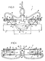
- the invention relates to the TOFD control of a welded joint 1, which joins end to end two metal parts 2, 3, such as plates, in particular with chamfered edges, the assembly having a given thickness e, typically between 5 mm and 100 mm.
- the equipment for implementing the method so as to control the welded joint 1 and the adjacent zones, in particular to detect possible defects of the crack type, is brought and moved along the joint to be inspected, that is to say on one side of the assembly constituted by the welded joint 1 and the two parts 2, 3 welded to one another.
- This equipment comprises, as a general part of "acquisition” 4, essentially two translators 5, 6, one transmitter and the other receiver of ultrasonic waves, interconnected by a linkage 7 which maintains them at a spacing E.
- the two translators 5, 6 are respectively placed above the edges of the two parts 2, 3 and on either side of the welded joint 1, the linkage 7 overlapping the joint 1 extending transversely thereto.
- the figure 2 is a synoptic diagram of the equipment showing on the right its "acquisition” part 4, with the two translators 5, 6 connected by the linkage 7, and on the left the electronic part 8, which is connected to the "acquisition” part 4 and which ensures in particular the processing and visualization of the measurements made.
- the electronic part 8 comprises an ultrasonic transmitter 9, connected at 10 to the ultrasonic wave emitter translator 5, and an ultrasonic receiver 11 connected at 12 to the ultrasonic wave receiver translator 6.
- the “acquisition” part 4 also comprises an autonomous water supply system under pressure, schematized at 15, connected by tubes (detailed below) to the two translators 5, 6.
- the linkage 7 consists of two parallel straight rods 16 and 17, held by a common central support 18. On these rods 16 and 17 are slidably mounted, on either side of the central support 18, two transverse axes 19 and 20.
- the first transverse axis 19 serves to support the translator 5 and the second transverse axis 20 serves to support the other translator 6, the arrangement being symmetrical.
- Each translator 5 or 6 is thus mounted mobile in translation along the rods 16 and 17 of the linkage 7, which allows to adjust the spacing E between the two translators 5 and 6.
- the inclination of the two translators 5, 6 is adjustable, by pivoting about the respective axes 19 and 20.
- the respective locking screws 21 and 22 are provided for the immobilization of the two translators 5 and 6 in the selected angular positions. .
- the pressurized water supply system 15 comprises a common tube 30 terminating in a "Y" of distribution 31, from which two flexible tubes 32, 33 leave, which end respectively to the two translators 5, 6, more particularly to the water inlet connection 27 of each translator.
- the piezoelectric elements 24 of the two translators 5 and 6 are rectangular or oblong piezoelectric ceramics, for example 6 ⁇ 4 mm, operating on longitudinal waves with an acoustic beam that can range from 30 ° to 80 °, preferably from 50 ° to 70 °. .
- the operating frequencies are, for their part, between 1 and 20 MHz, preferably between 6 and 18 MHz, and even more preferably between 6.5 MHz and 8.5 MHz for thicknesses of less than 10 mm or between 15 and 20 MHz, preferably of the order of 18 MHz for thicknesses of less than 10 mm, and / or with an associated bandwidth of 75% ⁇ 25% with respect to the center frequency at -6 dB.
- Rectangular ceramics with a length of between 5 and 20 mm and a width of between 2 and 8 mm can be used.
- Using oblong or rectangular ceramics makes it possible to obtain a strong divergence of the ultrasonic beam and thus to insonify the entire volume to be inspected.
- TOFD translators referenced 5-60 OL 55 sold by the company METALSCAN.
- a sound beam of 30 to 65 ° can be used to inspect thickness ranges between 10 and 300 mm.
- the spacing E of the two translators 5, 6, more particularly their respective emergence points 26, is adjusted as a function of the width and the thickness of the welded joint 1.
- the ultrasonic path of the side wave is indicated in I, and the path of the background echo in II, the "insonified" volume having been greyed out.
- a 24 dB battery preamplifier can be used to improve the signal-to-noise ratio.
- the representation of the received signals can be notably displayed at 14, in "B-SCAN rectified” mode, that is to say with a display of the time as a function of the amplitude of the signal.
- a lateral shift D of the set of two translators 5, 6, on one side or the other of the center of the welded joint 1, may facilitate the search for defects on the edge of this welded joint 1.
- the detection by the TOFD technique described above is combined with a detection according to the so-called OLI technique, for Longitudinal Inclined Wave, also called Creeping Waves technique.
- such a combination TOFD / OLI is particularly advantageous because it allows effective detection of cracks with a 3-way control device, that is to say three translators, and not only defects, such as cracks, more than 5 mm deep but also those less than 5 mm deep which are sometimes masked by the lateral wave, during a TOFD examination alone.
- the analysis of the signals is then done by A-SCAN, B-SCAN, C-SCAN and / or D-SCAN type imagery by means of a filtering system, in real time or deferred, or of a calculation system capable of extracting a characterization of the indication highlighted.
- the VENUS software from the company METALSCAN which produces representations of the signals in B-SCAN or D-SCAN mode from a high frequency signal (HF) or the MIDAS software from TECNATOM or any other equivalent software is used. .
- Frequency components of the recorded signals can be further measured by analysis of the Fourier transform.
- the OLI technique makes it possible to detect surface defects, opening or non-opening on the surface, up to a depth ranging, depending on the case, from approximately 0.5 mm to 18 mm, which makes it possible to complete effectively the area of thickness whose examination is not always optimal with the TOFD technique.
- the minimum size of the discontinuities and other cracks detectable effectively by TOFD and OLI techniques is of the order of 0.5 mm, whereas the maximum size corresponds to a through crack, that is to say, all the way through. thickness of the joint.
- the OLI technique is used to control cracks of less than 5 mm, located on the side of the sounding face, by insonification with longitudinal waves inclined between 70 and 90 °, preferably about 76 °. angle of refraction, and at a frequency between 1.5 and 4 MHz, for example of the order of 2 MHz.
- the ceramic or ceramics used for the implementation of the OLI technique are preferably rectangular, for example 5 ⁇ 10 mm, and the two ceramics forming a translator operating in separate transmission and reception and / or for a roof angel ( roof angle ) between 5 and 15 °, preferably of the order of 10 °.
- Standard FIDM 76-2 type translators sold by METALSCAN can be used.
- the figure 7 schematically a translator 57 used to implement the OLI technique so as to emit inclined longitudinal waves (arrow F4) for detecting small thickness defects in a weld joint 50 joining two metal parts 51, 52.
- the translator 57 is composed of a longitudinal wave transmitting ceramic 53 and a sound wave receiving ceramic 54 carried one and the other by an inclined shoe 55, for example made of plexiglass or the like, which forms an angle of approximately 27 ° ( ⁇ 2 °) with the surface of the workpiece in the plane of incidence.
- the roof angle ⁇ of the ceramics 53, 54 is between 5 and 15 °, preferably of the order of 10 °.
- the refracted longitudinal sound waves are sent in the direction of the arrow F4 to the weld joint 50 at an angle ⁇ of the order of 76 ° relative to the surface of the workpiece.
- the angle ⁇ is between 26 and 29 ° and corresponds to the angle of incidence of the plexiglass machined sole.
- the translator 57 is passed successively on either side of the weld joint 50 and the longitudinal sound waves are sent according to the angle ⁇ of 76 ° and at a frequency of 2 MHz, which makes it possible to insonify the whole of the upper volume of the welded joint 50.
- the inspection can be completed by off-set passages in TOFD modes as shown schematically in FIG. Figure 9 by means of the translating device 5, 6 of the Figure 1 , which makes it possible to cover the entire width to be inspected, that is to say all the area 58 thermally affected during welding.
- the Figure 10 schematizes the principle of the combination of a TDOF detection and an OLI detection according to the invention of a weld 50 between two parts 51, 52.
- Passes i) and ii) in TOFD mode are done with A-A, B-B, C-C translators which are identical here; the waves being sent at an angle of 55 ° and at a frequency of 7.5 MHz.
- the invention encompasses all variants of implementation and application respecting the above principle, regardless of the particular constructive details of the implementation equipment, for example at the structure of its linkage, the form or dimension of the translators.
- electronic focusing using multi-element translators would also fall within the scope of the invention.
Landscapes
- Physics & Mathematics (AREA)
- Biochemistry (AREA)
- Health & Medical Sciences (AREA)
- Life Sciences & Earth Sciences (AREA)
- Chemical & Material Sciences (AREA)
- Analytical Chemistry (AREA)
- General Health & Medical Sciences (AREA)
- General Physics & Mathematics (AREA)
- Immunology (AREA)
- Pathology (AREA)
- Acoustics & Sound (AREA)
- Engineering & Computer Science (AREA)
- Mechanical Engineering (AREA)
- Investigating Or Analyzing Materials By The Use Of Ultrasonic Waves (AREA)
Claims (15)
- Ultraschall-Prüfverfahren von Schweißverbindungen (1, 50), insbesondere von Schweißverbindungen (1, 50), die zwei Metallteile (2, 3; 51, 52) auf Stoß miteinander verbinden, wobei man die Prüfung der Verbindung (1, 50) folgendermaßen durchführta) man verfährt anhand des TOFD-Verfahrens (Time of Flight Diffraction) in Längsrichtung oder Umfangsrichtung in einem Durchgang entlang der zu prüfenden Schweißverbindung (1) zumindest ein Paar, das durch einen ersten Transduktor (5) und einen zweiten Transduktor (6) gebildet wird, der eine Sender und der andere Empfänger von Ultraschallwellen, wobei die besagten Transduktoren (5, 6) seitlich beiderseits der zu prüfenden Verbindung (1) positioniert sind, wobei die besagten Transduktoren (5, 6) piezoelektrische Keramiken oder Kristalle umfassen, um jeden Fehler der Verbindung (1, 50) zu erkennen, der sich in einer Stärke von mindestens 10 mm befindet.b) man verfährt in einem Durchgang entlang der zu prüfenden Schweißverbindung (1) unter Anwendung der Technik der geneigten Longitudinalwelle ("OLI"), die durch Insonifizierung zumindest eines Teils der zu prüfenden Verbindung (1, 50) mit geneigten longitudinalen Schallwellen mit einem Winkel (β) zwischen 70° und 90° als Refraktionswinkel angewandt wird, zumindest einen dritten Transduktor (57, 53, 54, 55) um jeden Fehler der Verbindung (1, 50) zu erkennen, der sich in einer Stärke zwischen 0,5 mm und 15 mm befindet.
- Verfahren nach Anspruch 1, dadurch gekennzeichnet, dass im Schritt a) der erste und der zweite Transduktor (5, 6) piezoelektrische Keramiken oder Kristalle in rechteckiger oder länglicher Form (24) umfasst.
- Verfahren nach einem der Ansprüche 1 oder 2, dadurch gekennzeichnet, dass im Schritt a) der erste und der zweite Transduktor (5, 6) ein Frequenzband von über 60% der zentralen Frequenz und eine Frequenz zwischen 1 und 20 MHz, vorzugsweise zwischen 6 und 18 MHz aufweisen.
- Verfahren nach einem der Ansprüche 1 bis 3, dadurch gekennzeichnet, dass es den seitlichen Versatz (D) des Ultraschall-Transduktorpaares (5, 6) im Verhältnis zur Mitte oder zur Achse der Schweißverbindung (1, 50) umfasst.
- Verfahren nach einem der Ansprüche 1 bis 4, dadurch gekennzeichnet, dass man im Schritt a) jeden Fehler der Verbindung (1, 50) erfasst, der sich in einer Stärke zwischen 10 und 300 mm, vorzugsweise aber zwischen 10 und 60 mm befindet.
- Verfahren nach Anspruch 1, dadurch gekennzeichnet, dass die "OLI" Technik im Schritt b) durch Insonifizierung zumindest eines Teils der zu prüfenden Verbindung (1, 50) mit geneigten longitudinalen Schallwellen mit einem Winkel (β) von etwa 76° als Refraktionswinkel angewandt wird, und/ oder mit einer Frequenz zwischen 1,5 und 4 MHz, im Speziellen in der Größenordnung von 2 MHz.
- Verfahren nach einem der Ansprüche 1 bis 6, dadurch gekennzeichnet, dass der Schritt b) nacheinander beiderseits der zu prüfenden Schweißverbindung (1, 50) ausgeführt wird.
- Verfahren nach einem der Ansprüche 1, 6 oder 7, dadurch gekennzeichnet, dass man im Schritt b) jeden Fehler der Verbindung (1, 50) erfasst, der sich in einer Stärke zwischen 0,5 mm und 20 mm, vorzugsweise zwischen 0,5 mm und 10 mm befindet.
- Verfahren nach einem der Ansprüche 1, 6 bis 8, dadurch gekennzeichnet, dass man im Schritt b) zumindest einen dritten Transduktor (57, 53, 54, 55) verwendet, der eine Schallemissionskeramik (53) umfasst, mit der man Schallwellen in Richtung der Schweißnaht (1, 50) aussenden kann, und eine Empfangskeramik (54) für Ultraschallwellen, mit der man Ultraschallwellen empfangen kann.
- Verfahren nach einem der Ansprüche 1 bis 9, dadurch gekennzeichnet, dass es eine Eichphase des oder der Paare an Ultraschall-Transduktoren (5, 6) ausgehend von einer Eichkerbe mit einer bestimmten Tiefe umfasst, die einen Riss simuliert, und vorzugsweise eine Kerbe in einer Länge von etwa 10 mm und einer Tiefe in der Größenordnung von 1 mm.
- Verfahren nach einem der Ansprüche 1 bis 10, dadurch gekennzeichnet, dass es zumindest einen Analyseschritt zumindest eines Signals umfasst, das durch einen oder jeden Empfangstransduktor im Laufe des Abfahrens der Schweißverbindung (1, 50) empfangen wird, um jeden Fehler, vor allem jeden Riss (34) zu erkennen, und vorzugsweise um dessen Höhe oder Abmessung zu bestimmen oder zu bewerten.
- Verfahren nach einem der Ansprüche 1 bis 11, dadurch gekennzeichnet, dass die Stärke (e) zwischen 5 mm und zumindest 60 mm liegt und die Teile Wände von Ausrüstungen oder Komponenten sind, die unter Druck arbeiten, und chemischen oder petrochemischen Einheiten, Atomkraftwerken oder ähnlichem, Strukturen von Flugmaschinen, Elementen oder Teilen von Rotationsmaschinen, Kanalisationen, Eisenbahnschienen oder anderen verschweißten Baugruppen angehören.
- Gerät zum Anwenden des Ultraschall-Prüfverfahrens von Schweißverbindungen nach irgendeinem der Ansprüche 1 bis 12, dadurch gekennzeichnet, dass es folgendes umfasst:- zumindest ein Paar, das aus einem ersten und einem zweiten Transduktor (5, 6), der eine Sender und der andere Empfänger von Ultraschallwellen, wobei die besagten Transduktoren (5, 6) seitlich beiderseits der zu prüfenden Verbindung (1) positioniert sind, und die angeordnet sind, um die TOFD Technik durch Verfahren in Längsrichtung oder Umfangsrichtung entlang der zu prüfenden Schweißverbindung anwenden zu können, um jeden Fehler der Verbindung (1, 50) in einem Durchgang zu erkennen, der sich in einer Stärke von mindestens 10 mm befindet, wobei die beiden Transduktoren (5, 6) piezoelektrische Keramiken oder Kristalle (24) verwenden und die beiden Transduktoren (5, 6) mechanisch durch eine gemeinsame Halterung (7) verbunden sind, die ein Gestänge (16, 17) umfasst, das angeordnet ist, um eine Einstellung des Abstandes (E) zwischen diesen beiden Transduktoren (5, 6) zu ermöglichen, eine schwenkbare Montage (Achsen 19, 20) eines jeden Transduktors (5, 6), mit Mitteln zum Blockieren (21, 22) in einer gewählten Winkelposition, und auch an eine Flüssigkeitszuführung (15, 30 bis 33), im Speziellen Wasser, angeschlossen sind, zur akustischen Kopplung dieser Transduktoren (5, 6) mit dem zu prüfenden Element (1, 2, 3),- zumindest einen dritten Transduktor (57, 53, 54, 55), der angeordnet ist, um die Technik der geneigten Longitudinalwelle ("OLI") anwenden zu können, die durch Insonifizierung zumindest eines Teils der zu prüfenden Verbindung (1, 50) mit geneigten longitudinalen Schallwellen mit einem Winkel (β) zwischen 70° und 90° als Refraktionswinkel angewandt wird, und durch Verfahren entlang der zu prüfenden Schweißverbindung (1), um jeden Fehler der Verbindung (1, 50) zu erfassen, der sich in einer Stärke zwischen 0,5 mm und 15 mm befindet, und- Mittel zum Bearbeiten (8) der Messwerte, wobei die Transduktoren noch mit den besagten Bearbeitungsmitteln (8) der Messwerte verbunden sind.
- Gerät nach Anspruch 13, dadurch gekennzeichnet, dass die gemeinsame Halterung (7) der beiden Ultraschall-Transduktoren (5, 6) eine Montage umfasst, die einen seitlichen Versatz (D) des Transduktorpaares (5, 6) im Verhältnis zur Mitte der zu prüfenden Schweißverbindung (1) ermöglicht.
- Gerät nach Anspruch 13, dadurch gekennzeichnet, dass der besagte dritte Transduktor (57, 53, 54, 55) eine Sendekeramik (53) von Wellen umfasst, die es ermöglicht, Schallwellen auszusenden und eine Keramik zum Empfangen (54) von Schallwellen, die den Empfang von Schallwellen ermöglicht.
Applications Claiming Priority (3)
| Application Number | Priority Date | Filing Date | Title |
|---|---|---|---|
| FR0207441 | 2002-06-17 | ||
| FR0207441A FR2840991B1 (fr) | 2002-06-17 | 2002-06-17 | Procede de controle par ultrasons de joints soudes |
| PCT/FR2003/001798 WO2003106994A1 (fr) | 2002-06-17 | 2003-06-13 | Procede de contrôle par ultrasons de joints soudes |
Publications (2)
| Publication Number | Publication Date |
|---|---|
| EP1516178A1 EP1516178A1 (de) | 2005-03-23 |
| EP1516178B1 true EP1516178B1 (de) | 2015-12-09 |
Family
ID=29595308
Family Applications (1)
| Application Number | Title | Priority Date | Filing Date |
|---|---|---|---|
| EP03760034.3A Expired - Lifetime EP1516178B1 (de) | 2002-06-17 | 2003-06-13 | Verfahren zur Ultraschallkontrolle von Schweissverbindungen |
Country Status (5)
| Country | Link |
|---|---|
| US (1) | US7168322B2 (de) |
| EP (1) | EP1516178B1 (de) |
| AU (1) | AU2003263235A1 (de) |
| FR (1) | FR2840991B1 (de) |
| WO (1) | WO2003106994A1 (de) |
Families Citing this family (39)
| Publication number | Priority date | Publication date | Assignee | Title |
|---|---|---|---|---|
| NL1024726C2 (nl) * | 2003-11-06 | 2005-05-09 | Roentgen Tech Dienst Bv | Werkwijze voor het controleren van een las tussen twee metalen pijpleidingen. |
| MD2839C2 (ro) * | 2004-11-05 | 2006-05-31 | Андрей Аким ТКАЧЕНКО | Procedeu de defectoscopie ultrasonică a cordoanelor de sudură |
| US8183493B2 (en) * | 2005-09-28 | 2012-05-22 | General Electric Company | Ultrasonic system for monitoring a weld operation |
| JP4910770B2 (ja) * | 2007-02-28 | 2012-04-04 | Jfeスチール株式会社 | 管体の超音波探傷装置および超音波探傷方法 |
| JP4839333B2 (ja) * | 2008-03-19 | 2011-12-21 | 日立Geニュークリア・エナジー株式会社 | 超音波検査方法および超音波検査装置 |
| US20090283569A1 (en) * | 2008-05-13 | 2009-11-19 | General Electric Company | System and method for monitoring welding |
| US8746069B2 (en) * | 2008-10-20 | 2014-06-10 | Fluor Technologies Corporation | Devices and methods of ultrasound time of flight diffraction sensitivity demonstration |
| US20100169053A1 (en) * | 2008-12-30 | 2010-07-01 | Caterpillar Inc. | Method for creating weldment inspection documents |
| US7900517B2 (en) * | 2009-06-16 | 2011-03-08 | Rontgen Technische Dienst B.V. | System and method for inspecting a pipeline with ultrasound |
| NL2003154C2 (en) * | 2009-07-08 | 2011-01-11 | R0Ntgen Tech Dienst B V | Method for ultrasonic sizing. |
| JP5746321B2 (ja) * | 2010-04-23 | 2015-07-08 | シーメンス ヴェ メタルス テクノロジーズ エスアーエスSiemens VAI Metals Technologies SAS | 2つの金属ストリップの2つの横方向端のバット溶接の超音波検査のための方法及び装置 |
| US20120091185A1 (en) * | 2010-10-18 | 2012-04-19 | Georgia Tech Research Corporation | In-process weld geometry methods & systems |
| CN103299185A (zh) * | 2011-01-11 | 2013-09-11 | 西门子公司 | 用于确定具有分布于层压材料中的多个纤维的纤维强化部件中的纤维取向的方法 |
| CA2806482A1 (en) * | 2011-02-03 | 2012-08-09 | Absolute Nde International Inc. | Method for ultrasonic inspection of welds |
| JP5733504B2 (ja) * | 2011-03-09 | 2015-06-10 | 株式会社Ihi | 溶接部の欠陥検出方法 |
| DE102011109717B3 (de) * | 2011-08-06 | 2012-10-11 | Ndt Systems & Services Gmbh & Co. Kg | Verfahren und Sensorträger zur Aufdachungsmessung von Rohrleitungen mittels Ultraschallprüfung |
| CN102435674B (zh) * | 2011-09-16 | 2013-03-27 | 国家电网公司 | 一种检测金属部件母材内壁裂纹及腐蚀缺陷的方法 |
| FR2984507B1 (fr) | 2011-12-16 | 2017-02-17 | Soudure Inst De | Dispositif de controle ultrasonore non destructif |
| US9261490B2 (en) * | 2012-03-29 | 2016-02-16 | J. Ray Mcdermott, S.A. | Ultrasonic transducer arrangement |
| US20130268214A1 (en) * | 2012-04-04 | 2013-10-10 | Siemens Aktiengesellschaft | Probabilistic fatigue life prediction using ultrasonic inspection data considering eifs uncertainty |
| WO2014062467A1 (en) * | 2012-10-15 | 2014-04-24 | Shell Oil Company | A method of locating and sizing fatigue cracks |
| EP2925968A4 (de) * | 2012-12-03 | 2016-01-27 | United Technologies Corp | Verfahren zur herstellung eines rotors eines mantelstromtriebwerks |
| US9207214B2 (en) * | 2013-04-30 | 2015-12-08 | General Electric Company | Auto beam optimization for phased array weld inspection |
| FR3011332B1 (fr) * | 2013-09-30 | 2019-12-20 | Areva Np | Procede et dispositif de controle non destructif d'une soudure d'une piece de reacteur nucleaire |
| EP2963380B2 (de) * | 2014-07-04 | 2025-06-25 | Georg Fischer Rohrleitungssysteme AG | Berührungsloses Überprüfen einer Stumpfschweissung |
| KR101658122B1 (ko) * | 2015-05-07 | 2016-09-21 | (주)피앤에스 | 초음파를 사용하여 측정된 용접부의 상태를 화면에 표시하는 방법 및 장치 |
| CN104931582A (zh) * | 2015-06-16 | 2015-09-23 | 南车青岛四方机车车辆股份有限公司 | 薄板搭接窄焊缝超声快速无损检测方法与装置 |
| JP6703297B2 (ja) * | 2015-10-14 | 2020-06-03 | 日本製鉄株式会社 | タンデム探傷用治具及びタンデム探傷検査方法 |
| GB201803062D0 (en) | 2018-02-26 | 2018-04-11 | Gb Inspection Systems Ltd | Ultrasonic probe |
| JP7094192B2 (ja) * | 2018-10-17 | 2022-07-01 | 日立Geニュークリア・エナジー株式会社 | 超音波検査システム |
| CN110554089B (zh) * | 2019-09-09 | 2022-04-01 | 西安特种设备检验检测院 | 焊接接头的检测方法、装置、设备和存储介质 |
| RU2740168C1 (ru) * | 2020-03-20 | 2021-01-12 | Общество с ограниченной ответственностью "Научно-производственный центр неразрушающего контроля "ЭХО+" | Способ определения координаты отражателя в сечении, перпендикулярном сварному соединению по TOFD-эхосигналам |
| US11686710B2 (en) | 2020-03-31 | 2023-06-27 | Evident Canada, Inc. | Longitudinal and circumferential ultrasound scanner |
| USD1103806S1 (en) | 2020-10-22 | 2025-12-02 | Evident Canada, Inc. | Scanner frame |
| US20220146460A1 (en) * | 2020-11-11 | 2022-05-12 | Southwest Research Institute | Guided wave testing of welds in pipelines and plate structures |
| CN112834616B (zh) * | 2021-01-04 | 2022-10-14 | 中车青岛四方机车车辆股份有限公司 | 一种焊缝检测装置及检测方法 |
| WO2023025368A1 (de) * | 2021-08-23 | 2023-03-02 | NDT Global Corporate Ltd. Ireland | Aufdachungsbestimmung in rohren |
| CN113533534B (zh) * | 2021-08-31 | 2025-03-21 | 上海地铁维护保障有限公司 | 一种高精度焊缝缺陷检测装置 |
| FR3149693A1 (fr) * | 2023-06-06 | 2024-12-13 | Onet Technologies Cn | procédé et dispositif de contrôle ultrasonore non destructif d’une pièce métallique ou d’un cordon de soudure |
Family Cites Families (23)
| Publication number | Priority date | Publication date | Assignee | Title |
|---|---|---|---|---|
| US3201864A (en) * | 1960-11-25 | 1965-08-24 | Sonobond Corp | Method and apparatus for ultrasonic welding |
| US3302453A (en) * | 1963-04-15 | 1967-02-07 | American Mach & Foundry | Method of inspection utilizing ultrasonic energy |
| US3332278A (en) * | 1963-07-15 | 1967-07-25 | American Mach & Foundry | Ultrasonic flaw detection |
| US3436958A (en) * | 1965-10-11 | 1969-04-08 | American Mach & Foundry | Ultrasonic pipe testing method and apparatus |
| US3540267A (en) * | 1967-10-18 | 1970-11-17 | American Mach & Foundry | Ultrasonic testing of drill pipe and the like |
| US3868847A (en) | 1972-12-04 | 1975-03-04 | Walter A Gunkel | System and apparatus for inspecting elongated welds |
| DE2613799C2 (de) * | 1976-03-29 | 1979-11-22 | Mannesmann Ag, 4000 Duesseldorf | Verfahren zum Einrichten von Ultraschall-Prüfanlagen |
| FR2566536B1 (fr) * | 1984-06-25 | 1987-10-02 | Cence Mario | Traducteur a ultrasons polyvalent adaptable aux configurations d'examen |
| GB2195022B (en) * | 1986-09-08 | 1990-11-28 | Atomic Energy Authority Uk | Ultrasonic scanning apparatus |
| GB8628662D0 (en) * | 1986-12-01 | 1987-01-07 | Atomic Energy Authority Uk | Ultrasonic scanning apparatus |
| GB8714002D0 (en) * | 1987-06-16 | 1987-07-22 | Atomic Energy Authority Uk | Ultrasonic transducer |
| DE3725658A1 (de) | 1987-08-03 | 1989-02-16 | Hoesch Ag | Verfahren und vorrichtung zur ankopplung eines ultraschall-pruefkopfes an einen pruefling |
| EP0685068B1 (de) * | 1993-02-18 | 1997-04-16 | KRAUTKRÄMER GmbH & Co. | Ultraschall-prüfvorrichtung für schweissnähte bei rohren, blechen und behältern |
| US5804730A (en) | 1995-10-10 | 1998-09-08 | Pfannenstiel; Richard A. | Ultrasonic testing method |
| FR2750502B1 (fr) * | 1996-06-27 | 1998-08-21 | Jeumont Ind | Dispositif et procede de controle par ultrasons d'une piece de forte epaisseur |
| US5814731A (en) * | 1997-01-28 | 1998-09-29 | Alexander; Alton Michel | Ultrasonic scanning apparatus for nondestructive site characterization of structures using a planar based acoustic transmitter and receiver in a rolling pond |
| JPH11108902A (ja) * | 1997-09-30 | 1999-04-23 | Mitsubishi Heavy Ind Ltd | 二探触子による管の探傷方法 |
| US6125704A (en) * | 1998-01-16 | 2000-10-03 | Shell Oil Company | Ultrasonic technique for inspection of weld and heat-affected zone for localized high temperature hydrogen attack |
| US6332361B1 (en) * | 1998-10-14 | 2001-12-25 | Daido Tokushuko Kabushiki Kaisha | Method for evaluating bonding properties of a metallic pipe |
| JP2001296282A (ja) * | 2000-04-12 | 2001-10-26 | Hatsuden Setsubi Gijutsu Kensa Kyokai | 固体内弾性波伝搬の可視化方法および装置 |
| US6405596B1 (en) * | 2000-10-13 | 2002-06-18 | Chicago Bridge & Iron Company | Ultrasonic austenitic weld seam inspection method and apparatus |
| US6684706B2 (en) * | 2000-11-29 | 2004-02-03 | Cooper Cameron Corporation | Ultrasonic testing system |
| US7093490B2 (en) * | 2004-02-23 | 2006-08-22 | Hitachi, Ltd. | Ultrasonic flaw detecting method and ultrasonic flaw detector |
-
2002
- 2002-06-17 FR FR0207441A patent/FR2840991B1/fr not_active Expired - Fee Related
-
2003
- 2003-06-13 US US10/518,139 patent/US7168322B2/en not_active Expired - Lifetime
- 2003-06-13 AU AU2003263235A patent/AU2003263235A1/en not_active Abandoned
- 2003-06-13 WO PCT/FR2003/001798 patent/WO2003106994A1/fr not_active Ceased
- 2003-06-13 EP EP03760034.3A patent/EP1516178B1/de not_active Expired - Lifetime
Also Published As
| Publication number | Publication date |
|---|---|
| WO2003106994A1 (fr) | 2003-12-24 |
| EP1516178A1 (de) | 2005-03-23 |
| US7168322B2 (en) | 2007-01-30 |
| US20050223807A1 (en) | 2005-10-13 |
| AU2003263235A1 (en) | 2003-12-31 |
| FR2840991A1 (fr) | 2003-12-19 |
| FR2840991B1 (fr) | 2005-05-06 |
Similar Documents
| Publication | Publication Date | Title |
|---|---|---|
| EP1516178B1 (de) | Verfahren zur Ultraschallkontrolle von Schweissverbindungen | |
| EP0204143B1 (de) | Verfahren Und Vorrichtung zur Feststellung von internen Fehlern an den Flanken des Kopfes einer Eisenbahnschiene mittels Ultraschall | |
| EP2158479B1 (de) | Verfahren und vorrichtung zur automatischen zerstörungsfreien inspektion von hohlachsen mit variablen innen- und aussenradiusprofilen | |
| WO2010097269A1 (en) | A method for testing pipeline welds using ultrasonic phased arrays | |
| US20060130586A1 (en) | Configurations and methods for ultrasound time of flight diffraction analysis | |
| EP2669672B1 (de) | Vorrichtung und Verfahren zur Inspektion eines Rohres | |
| CA3108506C (fr) | Dispositif d'examen de l'interieur d'une conduite par ultrason multi-element | |
| CA2390712A1 (en) | Method for inspecting clad pipe | |
| JP7156912B2 (ja) | ランプを有する構造体の超音波検査 | |
| NL1024726C2 (nl) | Werkwijze voor het controleren van een las tussen twee metalen pijpleidingen. | |
| EP0099816B1 (de) | Verfahren und Vorrichtung für Ultraschall Echographie | |
| EP2605009A1 (de) | Vorrichtung zur zerstörungsfreien Gruppenstrahler-Ultraschallkontrolle | |
| EP4630802A1 (de) | Verfahren zur erkennung von rissen in einem rohrförmigen rohr | |
| Casula et al. | Ultrasonic nondestructive testing of complex components with flexible phased-array transducers | |
| RU2641613C2 (ru) | Способ контроля качества посадок с натягом | |
| CA2780329A1 (fr) | Systeme comportant un capteur-roue de mesures non destructices d'objets , capteur-roue et methode d'inspection correspondants | |
| JP2001330594A (ja) | 金属管接合体の検査方法 | |
| Hesse et al. | Defect detection in rails using ultrasonic surface waves | |
| EP3289348B1 (de) | Verfahren zur steuerung von verschweissungen mittels ultraschall | |
| EP1705483B1 (de) | Bestimmung der Fläche einer lateralen Schattenzone in einem Ultraschallprüfungsverfahren | |
| WO2001071339A1 (fr) | Procede d'evaluation de resilience d'un assemblage soude et appareil d'analyse correspondant mesurant des vitesses d'ondes ultrasonores superficielles | |
| WO2026002920A1 (fr) | Procédé et ensemble d'inspection par ultrasons d'une tuyauterie | |
| JP2001165916A (ja) | ペンシル型局部水浸超音波探触子及びそれを用いた溶接部の探傷方法 | |
| Hörchens et al. | Adaptive ultrasonic imaging of electric resistance welded pipeline seams | |
| FR2937136A1 (fr) | Procede de controle non-destructif utilisant des ondes de lamb pour determiner des zones d'une structure comportant des defauts |
Legal Events
| Date | Code | Title | Description |
|---|---|---|---|
| PUAI | Public reference made under article 153(3) epc to a published international application that has entered the european phase |
Free format text: ORIGINAL CODE: 0009012 |
|
| 17P | Request for examination filed |
Effective date: 20050117 |
|
| AK | Designated contracting states |
Kind code of ref document: A1 Designated state(s): AT BE BG CH CY CZ DE DK EE ES FI FR GB GR HU IE IT LI LU MC NL PT RO SE SI SK TR |
|
| AX | Request for extension of the european patent |
Extension state: AL LT LV MK |
|
| DAX | Request for extension of the european patent (deleted) | ||
| RAP1 | Party data changed (applicant data changed or rights of an application transferred) |
Owner name: L'AIR LIQUIDE, SOCIETE ANONYME POUR L'ETUDE ET L'E |
|
| RAP1 | Party data changed (applicant data changed or rights of an application transferred) |
Owner name: L'AIR LIQUIDE, SOCIETE ANONYME POUR L'ETUDE ET L'E |
|
| 17Q | First examination report despatched |
Effective date: 20071123 |
|
| REG | Reference to a national code |
Ref country code: DE Ref legal event code: R079 Ref document number: 60348332 Country of ref document: DE Free format text: PREVIOUS MAIN CLASS: G01N0029260000 Ipc: G01N0029040000 |
|
| RIC1 | Information provided on ipc code assigned before grant |
Ipc: G01N 29/26 20060101ALI20130417BHEP Ipc: G01N 29/04 20060101AFI20130417BHEP Ipc: G01N 29/06 20060101ALI20130417BHEP Ipc: B23K 31/12 20060101ALI20130417BHEP |
|
| GRAP | Despatch of communication of intention to grant a patent |
Free format text: ORIGINAL CODE: EPIDOSNIGR1 |
|
| INTG | Intention to grant announced |
Effective date: 20150702 |
|
| GRAS | Grant fee paid |
Free format text: ORIGINAL CODE: EPIDOSNIGR3 |
|
| GRAA | (expected) grant |
Free format text: ORIGINAL CODE: 0009210 |
|
| AK | Designated contracting states |
Kind code of ref document: B1 Designated state(s): AT BE BG CH CY CZ DE DK EE ES FI FR GB GR HU IE IT LI LU MC NL PT RO SE SI SK TR |
|
| REG | Reference to a national code |
Ref country code: GB Ref legal event code: FG4D Free format text: NOT ENGLISH |
|
| REG | Reference to a national code |
Ref country code: AT Ref legal event code: REF Ref document number: 764800 Country of ref document: AT Kind code of ref document: T Effective date: 20151215 Ref country code: CH Ref legal event code: EP |
|
| REG | Reference to a national code |
Ref country code: IE Ref legal event code: FG4D Free format text: LANGUAGE OF EP DOCUMENT: FRENCH |
|
| REG | Reference to a national code |
Ref country code: DE Ref legal event code: R096 Ref document number: 60348332 Country of ref document: DE |
|
| REG | Reference to a national code |
Ref country code: NL Ref legal event code: MP Effective date: 20151209 |
|
| PG25 | Lapsed in a contracting state [announced via postgrant information from national office to epo] |
Ref country code: ES Free format text: LAPSE BECAUSE OF FAILURE TO SUBMIT A TRANSLATION OF THE DESCRIPTION OR TO PAY THE FEE WITHIN THE PRESCRIBED TIME-LIMIT Effective date: 20151209 |
|
| REG | Reference to a national code |
Ref country code: AT Ref legal event code: MK05 Ref document number: 764800 Country of ref document: AT Kind code of ref document: T Effective date: 20151209 |
|
| PG25 | Lapsed in a contracting state [announced via postgrant information from national office to epo] |
Ref country code: SE Free format text: LAPSE BECAUSE OF FAILURE TO SUBMIT A TRANSLATION OF THE DESCRIPTION OR TO PAY THE FEE WITHIN THE PRESCRIBED TIME-LIMIT Effective date: 20151209 Ref country code: GR Free format text: LAPSE BECAUSE OF FAILURE TO SUBMIT A TRANSLATION OF THE DESCRIPTION OR TO PAY THE FEE WITHIN THE PRESCRIBED TIME-LIMIT Effective date: 20160310 Ref country code: FI Free format text: LAPSE BECAUSE OF FAILURE TO SUBMIT A TRANSLATION OF THE DESCRIPTION OR TO PAY THE FEE WITHIN THE PRESCRIBED TIME-LIMIT Effective date: 20151209 Ref country code: NL Free format text: LAPSE BECAUSE OF FAILURE TO SUBMIT A TRANSLATION OF THE DESCRIPTION OR TO PAY THE FEE WITHIN THE PRESCRIBED TIME-LIMIT Effective date: 20151209 |
|
| REG | Reference to a national code |
Ref country code: FR Ref legal event code: PLFP Year of fee payment: 14 |
|
| PG25 | Lapsed in a contracting state [announced via postgrant information from national office to epo] |
Ref country code: IT Free format text: LAPSE BECAUSE OF FAILURE TO SUBMIT A TRANSLATION OF THE DESCRIPTION OR TO PAY THE FEE WITHIN THE PRESCRIBED TIME-LIMIT Effective date: 20151209 Ref country code: CZ Free format text: LAPSE BECAUSE OF FAILURE TO SUBMIT A TRANSLATION OF THE DESCRIPTION OR TO PAY THE FEE WITHIN THE PRESCRIBED TIME-LIMIT Effective date: 20151209 |
|
| PGFP | Annual fee paid to national office [announced via postgrant information from national office to epo] |
Ref country code: DE Payment date: 20160621 Year of fee payment: 14 |
|
| PG25 | Lapsed in a contracting state [announced via postgrant information from national office to epo] |
Ref country code: PT Free format text: LAPSE BECAUSE OF FAILURE TO SUBMIT A TRANSLATION OF THE DESCRIPTION OR TO PAY THE FEE WITHIN THE PRESCRIBED TIME-LIMIT Effective date: 20160411 Ref country code: SK Free format text: LAPSE BECAUSE OF FAILURE TO SUBMIT A TRANSLATION OF THE DESCRIPTION OR TO PAY THE FEE WITHIN THE PRESCRIBED TIME-LIMIT Effective date: 20151209 Ref country code: AT Free format text: LAPSE BECAUSE OF FAILURE TO SUBMIT A TRANSLATION OF THE DESCRIPTION OR TO PAY THE FEE WITHIN THE PRESCRIBED TIME-LIMIT Effective date: 20151209 Ref country code: EE Free format text: LAPSE BECAUSE OF FAILURE TO SUBMIT A TRANSLATION OF THE DESCRIPTION OR TO PAY THE FEE WITHIN THE PRESCRIBED TIME-LIMIT Effective date: 20151209 Ref country code: RO Free format text: LAPSE BECAUSE OF FAILURE TO SUBMIT A TRANSLATION OF THE DESCRIPTION OR TO PAY THE FEE WITHIN THE PRESCRIBED TIME-LIMIT Effective date: 20151209 |
|
| PGFP | Annual fee paid to national office [announced via postgrant information from national office to epo] |
Ref country code: FR Payment date: 20160627 Year of fee payment: 14 |
|
| REG | Reference to a national code |
Ref country code: DE Ref legal event code: R097 Ref document number: 60348332 Country of ref document: DE |
|
| PLBE | No opposition filed within time limit |
Free format text: ORIGINAL CODE: 0009261 |
|
| STAA | Information on the status of an ep patent application or granted ep patent |
Free format text: STATUS: NO OPPOSITION FILED WITHIN TIME LIMIT |
|
| PG25 | Lapsed in a contracting state [announced via postgrant information from national office to epo] |
Ref country code: DK Free format text: LAPSE BECAUSE OF FAILURE TO SUBMIT A TRANSLATION OF THE DESCRIPTION OR TO PAY THE FEE WITHIN THE PRESCRIBED TIME-LIMIT Effective date: 20151209 |
|
| 26N | No opposition filed |
Effective date: 20160912 |
|
| PG25 | Lapsed in a contracting state [announced via postgrant information from national office to epo] |
Ref country code: SI Free format text: LAPSE BECAUSE OF FAILURE TO SUBMIT A TRANSLATION OF THE DESCRIPTION OR TO PAY THE FEE WITHIN THE PRESCRIBED TIME-LIMIT Effective date: 20151209 |
|
| PG25 | Lapsed in a contracting state [announced via postgrant information from national office to epo] |
Ref country code: BE Free format text: LAPSE BECAUSE OF NON-PAYMENT OF DUE FEES Effective date: 20160630 |
|
| PG25 | Lapsed in a contracting state [announced via postgrant information from national office to epo] |
Ref country code: MC Free format text: LAPSE BECAUSE OF FAILURE TO SUBMIT A TRANSLATION OF THE DESCRIPTION OR TO PAY THE FEE WITHIN THE PRESCRIBED TIME-LIMIT Effective date: 20151209 |
|
| REG | Reference to a national code |
Ref country code: CH Ref legal event code: PL |
|
| GBPC | Gb: european patent ceased through non-payment of renewal fee |
Effective date: 20160613 |
|
| REG | Reference to a national code |
Ref country code: IE Ref legal event code: MM4A |
|
| PG25 | Lapsed in a contracting state [announced via postgrant information from national office to epo] |
Ref country code: CH Free format text: LAPSE BECAUSE OF NON-PAYMENT OF DUE FEES Effective date: 20160630 Ref country code: LI Free format text: LAPSE BECAUSE OF NON-PAYMENT OF DUE FEES Effective date: 20160630 |
|
| PG25 | Lapsed in a contracting state [announced via postgrant information from national office to epo] |
Ref country code: IE Free format text: LAPSE BECAUSE OF NON-PAYMENT OF DUE FEES Effective date: 20160613 Ref country code: GB Free format text: LAPSE BECAUSE OF NON-PAYMENT OF DUE FEES Effective date: 20160613 |
|
| REG | Reference to a national code |
Ref country code: DE Ref legal event code: R119 Ref document number: 60348332 Country of ref document: DE |
|
| REG | Reference to a national code |
Ref country code: FR Ref legal event code: ST Effective date: 20180228 |
|
| PG25 | Lapsed in a contracting state [announced via postgrant information from national office to epo] |
Ref country code: DE Free format text: LAPSE BECAUSE OF NON-PAYMENT OF DUE FEES Effective date: 20180103 |
|
| PG25 | Lapsed in a contracting state [announced via postgrant information from national office to epo] |
Ref country code: FR Free format text: LAPSE BECAUSE OF NON-PAYMENT OF DUE FEES Effective date: 20170630 Ref country code: CY Free format text: LAPSE BECAUSE OF FAILURE TO SUBMIT A TRANSLATION OF THE DESCRIPTION OR TO PAY THE FEE WITHIN THE PRESCRIBED TIME-LIMIT Effective date: 20151209 Ref country code: HU Free format text: LAPSE BECAUSE OF FAILURE TO SUBMIT A TRANSLATION OF THE DESCRIPTION OR TO PAY THE FEE WITHIN THE PRESCRIBED TIME-LIMIT; INVALID AB INITIO Effective date: 20030613 |
|
| PG25 | Lapsed in a contracting state [announced via postgrant information from national office to epo] |
Ref country code: LU Free format text: LAPSE BECAUSE OF NON-PAYMENT OF DUE FEES Effective date: 20160613 Ref country code: TR Free format text: LAPSE BECAUSE OF FAILURE TO SUBMIT A TRANSLATION OF THE DESCRIPTION OR TO PAY THE FEE WITHIN THE PRESCRIBED TIME-LIMIT Effective date: 20151209 |
|
| PG25 | Lapsed in a contracting state [announced via postgrant information from national office to epo] |
Ref country code: BG Free format text: LAPSE BECAUSE OF FAILURE TO SUBMIT A TRANSLATION OF THE DESCRIPTION OR TO PAY THE FEE WITHIN THE PRESCRIBED TIME-LIMIT Effective date: 20151209 |