EP1516178B1 - Method for ultrasonic control of weld joints - Google Patents
Method for ultrasonic control of weld joints Download PDFInfo
- Publication number
- EP1516178B1 EP1516178B1 EP03760034.3A EP03760034A EP1516178B1 EP 1516178 B1 EP1516178 B1 EP 1516178B1 EP 03760034 A EP03760034 A EP 03760034A EP 1516178 B1 EP1516178 B1 EP 1516178B1
- Authority
- EP
- European Patent Office
- Prior art keywords
- joint
- translators
- translator
- controlled
- ultrasonic
- Prior art date
- Legal status (The legal status is an assumption and is not a legal conclusion. Google has not performed a legal analysis and makes no representation as to the accuracy of the status listed.)
- Expired - Lifetime
Links
Images


Classifications
-
- G—PHYSICS
- G01—MEASURING; TESTING
- G01N—INVESTIGATING OR ANALYSING MATERIALS BY DETERMINING THEIR CHEMICAL OR PHYSICAL PROPERTIES
- G01N29/00—Investigating or analysing materials by the use of ultrasonic, sonic or infrasonic waves; Visualisation of the interior of objects by transmitting ultrasonic or sonic waves through the object
- G01N29/34—Generating the ultrasonic, sonic or infrasonic waves, e.g. electronic circuits specially adapted therefor
- G01N29/348—Generating the ultrasonic, sonic or infrasonic waves, e.g. electronic circuits specially adapted therefor with frequency characteristics, e.g. single frequency signals, chirp signals
-
- B—PERFORMING OPERATIONS; TRANSPORTING
- B23—MACHINE TOOLS; METAL-WORKING NOT OTHERWISE PROVIDED FOR
- B23K—SOLDERING OR UNSOLDERING; WELDING; CLADDING OR PLATING BY SOLDERING OR WELDING; CUTTING BY APPLYING HEAT LOCALLY, e.g. FLAME CUTTING; WORKING BY LASER BEAM
- B23K31/00—Processes relevant to this subclass, specially adapted for particular articles or purposes, but not covered by any single one of main groups B23K1/00 - B23K28/00
- B23K31/12—Processes relevant to this subclass, specially adapted for particular articles or purposes, but not covered by any single one of main groups B23K1/00 - B23K28/00 relating to investigating the properties, e.g. the weldability, of materials
-
- G—PHYSICS
- G01—MEASURING; TESTING
- G01N—INVESTIGATING OR ANALYSING MATERIALS BY DETERMINING THEIR CHEMICAL OR PHYSICAL PROPERTIES
- G01N29/00—Investigating or analysing materials by the use of ultrasonic, sonic or infrasonic waves; Visualisation of the interior of objects by transmitting ultrasonic or sonic waves through the object
- G01N29/04—Analysing solids
- G01N29/043—Analysing solids in the interior, e.g. by shear waves
-
- G—PHYSICS
- G01—MEASURING; TESTING
- G01N—INVESTIGATING OR ANALYSING MATERIALS BY DETERMINING THEIR CHEMICAL OR PHYSICAL PROPERTIES
- G01N29/00—Investigating or analysing materials by the use of ultrasonic, sonic or infrasonic waves; Visualisation of the interior of objects by transmitting ultrasonic or sonic waves through the object
- G01N29/04—Analysing solids
- G01N29/06—Visualisation of the interior, e.g. acoustic microscopy
- G01N29/0609—Display arrangements, e.g. colour displays
- G01N29/0645—Display representation or displayed parameters, e.g. A-, B- or C-Scan
-
- G—PHYSICS
- G01—MEASURING; TESTING
- G01N—INVESTIGATING OR ANALYSING MATERIALS BY DETERMINING THEIR CHEMICAL OR PHYSICAL PROPERTIES
- G01N29/00—Investigating or analysing materials by the use of ultrasonic, sonic or infrasonic waves; Visualisation of the interior of objects by transmitting ultrasonic or sonic waves through the object
- G01N29/04—Analysing solids
- G01N29/06—Visualisation of the interior, e.g. acoustic microscopy
- G01N29/0654—Imaging
- G01N29/069—Defect imaging, localisation and sizing using, e.g. time of flight diffraction [TOFD], synthetic aperture focusing technique [SAFT], Amplituden-Laufzeit-Ortskurven [ALOK] technique
-
- G—PHYSICS
- G01—MEASURING; TESTING
- G01N—INVESTIGATING OR ANALYSING MATERIALS BY DETERMINING THEIR CHEMICAL OR PHYSICAL PROPERTIES
- G01N2291/00—Indexing codes associated with group G01N29/00
- G01N2291/01—Indexing codes associated with the measuring variable
- G01N2291/011—Velocity or travel time
-
- G—PHYSICS
- G01—MEASURING; TESTING
- G01N—INVESTIGATING OR ANALYSING MATERIALS BY DETERMINING THEIR CHEMICAL OR PHYSICAL PROPERTIES
- G01N2291/00—Indexing codes associated with group G01N29/00
- G01N2291/04—Wave modes and trajectories
- G01N2291/042—Wave modes
- G01N2291/0421—Longitudinal waves
-
- G—PHYSICS
- G01—MEASURING; TESTING
- G01N—INVESTIGATING OR ANALYSING MATERIALS BY DETERMINING THEIR CHEMICAL OR PHYSICAL PROPERTIES
- G01N2291/00—Indexing codes associated with group G01N29/00
- G01N2291/04—Wave modes and trajectories
- G01N2291/042—Wave modes
- G01N2291/0422—Shear waves, transverse waves, horizontally polarised waves
-
- G—PHYSICS
- G01—MEASURING; TESTING
- G01N—INVESTIGATING OR ANALYSING MATERIALS BY DETERMINING THEIR CHEMICAL OR PHYSICAL PROPERTIES
- G01N2291/00—Indexing codes associated with group G01N29/00
- G01N2291/04—Wave modes and trajectories
- G01N2291/044—Internal reflections (echoes), e.g. on walls or defects
-
- G—PHYSICS
- G01—MEASURING; TESTING
- G01N—INVESTIGATING OR ANALYSING MATERIALS BY DETERMINING THEIR CHEMICAL OR PHYSICAL PROPERTIES
- G01N2291/00—Indexing codes associated with group G01N29/00
- G01N2291/10—Number of transducers
- G01N2291/102—Number of transducers one emitter, one receiver
-
- G—PHYSICS
- G01—MEASURING; TESTING
- G01N—INVESTIGATING OR ANALYSING MATERIALS BY DETERMINING THEIR CHEMICAL OR PHYSICAL PROPERTIES
- G01N2291/00—Indexing codes associated with group G01N29/00
- G01N2291/26—Scanned objects
- G01N2291/267—Welds
- G01N2291/2675—Seam, butt welding
Definitions
- the present invention relates to a method for the non-destructive ultrasonic testing of materials and, more particularly, welded joints joining, end to end, two metal parts, in particular of the plate or sheet type.
- This method allows the control, in manufacture and in service, of structures and equipment with welded joints, for example obtained by local melting, and may be the seat of flat defects like crack or volume defects; in this respect, the terms "defect” or "crack” will be used interchangeably.
- the method according to the invention may relate to the control of welded joints of pressure equipment or component walls, belonging to chemical or petrochemical units, nuclear power plants or the like, structures of flying machinery, rotating machine parts or parts, or pipelines, in situations which may require checks and in particular repeated examinations, such as examinations before and after heat treatment, or before and after repair, materials or assemblies, follow-up of defects evolution in pressure equipment (such as evolutionary cracks in service), industrial manufacturing controls, etc ...
- TOFD Time-Of-Flight Diffraction
- OLI Longitudinal Inclined Wave
- Creeping Waves technique is applicable to ultrasound control, and is described, for example in H. Wustenberg and A. Erhard, "Creeping Waves and Ultrasonic contol. Physical principle and application to the welded joint control principle ", Practical Rvis of Industrial Control ISSN 0373-8809; 1984, No. 127, pp 55.60 .
- the document GB-A-2198532 has proposed a method of TOFD ( time-of-flight diffraction ) inspection of welded objects located under water, such as oil extraction platforms, using two translators ( transducers in English) adjacent to each other. on the surface of the object to be inspected and spaced from each other, being located on either side of the weld joint in which any cracks must be detected.
- TOFD time-of-flight diffraction
- the document WO 02/31487 discloses a method of ultrasonic testing of welded joints, more particularly welded joints joining end-to-end two metal parts, wherein the control of the joint is carried out by moving along the welded joint to be checked, applying the technique of the longitudinal inclined wave, at least one pair formed of a first translator and a second translator, one transmitter and the other ultrasonic wave receiver, said translators being positioned laterally on either side of the seal check to detect any defects in the seal at a maximum thickness of 8-10 mm.
- the present invention thus aims to solve the problems existing in the prior art by proposing an improved welded seam control method for effectively covering at least the thickness range of between 10 mm and at least 60 mm, in a single pass along the joint to longitudinally or circumferentially, ie for linear or circular joints (pipe splicing), as well as the range of smaller thicknesses, ie the areas close to the surface having a thickness of between 0.5 mm and 5 mm, which are usually more difficult to inspect.
- the invention also aims to allow to test a zone of greater thickness or volume by using a reasonable number of translators.
- this invention also aims to provide a simple and autonomous equipment suitable for the implementation of the control method concerned at the industrial level.
- the solution of the present invention is then a method of ultrasonic testing of welded joints combining the "TOFD” technique and the "OLI” technique.
- the method uses ultrasonic transducers of this type with a wide frequency band, in particular greater than 60% of the central frequency, and having very short pulses, that is to say high frequencies, notably between 1 and 20 MHz, and preferably between 6 and 18 MHz.
- the method according to the invention also advantageously comprises the adaptation of the spacing between the two ultrasonic transducers, one transmitter and the other receiver, and / or the lateral offset of this pair of translators with respect to the center of the welded joint to control, to cover optimally with this pair of translators, a volume corresponding to the thickness of the joint to be controlled, and possibly including areas adjacent to this joint.
- the spacing adjustment between the two emergence points is adaptable here so that the reflection echo of the opposite wall controlled is at its amplitude close to the maximum.
- the processing procedure here takes into account not only the information contained in the usual signals, ranging from the lateral wave to the background echo, but also the information generated by the secondary waves, such as the mode transformations.
- broadband translators greater than 60% of the center frequency
- high frequencies preferably between 6 and 18 MHz.
- the method which is the subject of the invention thus makes it possible, in a rapid manner, that is to say the detection of any type of defect on the entirety of a welded joint, the height of the cracks being measurable with an accuracy of ⁇ 0 , 25 mm.
- a calibration phase of the pair or pairs of ultrasonic translators used for the implementation of the TOFD method from a calibration notch, in particular electro -peroded, of determined depth, located on a face of a calibration block, such an artificial notch simulating a crack.
- This notch may in particular have a thickness of between 0.5 mm and half the thickness of a calibration block whose thickness corresponds to that of the parts carrying the weld to be examined, or even on one of the parts themselves; in this case, it can be arranged on one side opposite to its sounding surface.
- the notch may have a height of about 1 mm when it is desired to detect very closed cracks.
- the measurement processing means can be made according to known techniques in the field of ultrasonic measuring and control devices.
- the measurements made can be memorized and stored, for later processing by software or by specific calculations, aimed at forming and visualizing images called "A-SCAN” and / or "B-SCAN", and to extract from these images anomalies or other discriminatory signs of defects welded controlled joints, to achieve a visual interpretation in real time or delayed, by signal analysis in automatic mode.
- a library of standard images can help operators to make decisions on the exam complements to be performed, and / or to diagnose the nature of the defects highlighted.
- Specific software may also provide additional means here to rule on a detected type of defect, in particular on the volumetric nature or not of the defect analyzed.
- the invention relates to the TOFD control of a welded joint 1, which joins end to end two metal parts 2, 3, such as plates, in particular with chamfered edges, the assembly having a given thickness e, typically between 5 mm and 100 mm.
- the equipment for implementing the method so as to control the welded joint 1 and the adjacent zones, in particular to detect possible defects of the crack type, is brought and moved along the joint to be inspected, that is to say on one side of the assembly constituted by the welded joint 1 and the two parts 2, 3 welded to one another.
- This equipment comprises, as a general part of "acquisition” 4, essentially two translators 5, 6, one transmitter and the other receiver of ultrasonic waves, interconnected by a linkage 7 which maintains them at a spacing E.
- the two translators 5, 6 are respectively placed above the edges of the two parts 2, 3 and on either side of the welded joint 1, the linkage 7 overlapping the joint 1 extending transversely thereto.
- the figure 2 is a synoptic diagram of the equipment showing on the right its "acquisition” part 4, with the two translators 5, 6 connected by the linkage 7, and on the left the electronic part 8, which is connected to the "acquisition” part 4 and which ensures in particular the processing and visualization of the measurements made.
- the electronic part 8 comprises an ultrasonic transmitter 9, connected at 10 to the ultrasonic wave emitter translator 5, and an ultrasonic receiver 11 connected at 12 to the ultrasonic wave receiver translator 6.
- the “acquisition” part 4 also comprises an autonomous water supply system under pressure, schematized at 15, connected by tubes (detailed below) to the two translators 5, 6.
- the linkage 7 consists of two parallel straight rods 16 and 17, held by a common central support 18. On these rods 16 and 17 are slidably mounted, on either side of the central support 18, two transverse axes 19 and 20.
- the first transverse axis 19 serves to support the translator 5 and the second transverse axis 20 serves to support the other translator 6, the arrangement being symmetrical.
- Each translator 5 or 6 is thus mounted mobile in translation along the rods 16 and 17 of the linkage 7, which allows to adjust the spacing E between the two translators 5 and 6.
- the inclination of the two translators 5, 6 is adjustable, by pivoting about the respective axes 19 and 20.
- the respective locking screws 21 and 22 are provided for the immobilization of the two translators 5 and 6 in the selected angular positions. .
- the pressurized water supply system 15 comprises a common tube 30 terminating in a "Y" of distribution 31, from which two flexible tubes 32, 33 leave, which end respectively to the two translators 5, 6, more particularly to the water inlet connection 27 of each translator.
- the piezoelectric elements 24 of the two translators 5 and 6 are rectangular or oblong piezoelectric ceramics, for example 6 ⁇ 4 mm, operating on longitudinal waves with an acoustic beam that can range from 30 ° to 80 °, preferably from 50 ° to 70 °. .
- the operating frequencies are, for their part, between 1 and 20 MHz, preferably between 6 and 18 MHz, and even more preferably between 6.5 MHz and 8.5 MHz for thicknesses of less than 10 mm or between 15 and 20 MHz, preferably of the order of 18 MHz for thicknesses of less than 10 mm, and / or with an associated bandwidth of 75% ⁇ 25% with respect to the center frequency at -6 dB.
- Rectangular ceramics with a length of between 5 and 20 mm and a width of between 2 and 8 mm can be used.
- Using oblong or rectangular ceramics makes it possible to obtain a strong divergence of the ultrasonic beam and thus to insonify the entire volume to be inspected.
- TOFD translators referenced 5-60 OL 55 sold by the company METALSCAN.
- a sound beam of 30 to 65 ° can be used to inspect thickness ranges between 10 and 300 mm.
- the spacing E of the two translators 5, 6, more particularly their respective emergence points 26, is adjusted as a function of the width and the thickness of the welded joint 1.
- the ultrasonic path of the side wave is indicated in I, and the path of the background echo in II, the "insonified" volume having been greyed out.
- a 24 dB battery preamplifier can be used to improve the signal-to-noise ratio.
- the representation of the received signals can be notably displayed at 14, in "B-SCAN rectified” mode, that is to say with a display of the time as a function of the amplitude of the signal.
- a lateral shift D of the set of two translators 5, 6, on one side or the other of the center of the welded joint 1, may facilitate the search for defects on the edge of this welded joint 1.
- the detection by the TOFD technique described above is combined with a detection according to the so-called OLI technique, for Longitudinal Inclined Wave, also called Creeping Waves technique.
- such a combination TOFD / OLI is particularly advantageous because it allows effective detection of cracks with a 3-way control device, that is to say three translators, and not only defects, such as cracks, more than 5 mm deep but also those less than 5 mm deep which are sometimes masked by the lateral wave, during a TOFD examination alone.
- the analysis of the signals is then done by A-SCAN, B-SCAN, C-SCAN and / or D-SCAN type imagery by means of a filtering system, in real time or deferred, or of a calculation system capable of extracting a characterization of the indication highlighted.
- the VENUS software from the company METALSCAN which produces representations of the signals in B-SCAN or D-SCAN mode from a high frequency signal (HF) or the MIDAS software from TECNATOM or any other equivalent software is used. .
- Frequency components of the recorded signals can be further measured by analysis of the Fourier transform.
- the OLI technique makes it possible to detect surface defects, opening or non-opening on the surface, up to a depth ranging, depending on the case, from approximately 0.5 mm to 18 mm, which makes it possible to complete effectively the area of thickness whose examination is not always optimal with the TOFD technique.
- the minimum size of the discontinuities and other cracks detectable effectively by TOFD and OLI techniques is of the order of 0.5 mm, whereas the maximum size corresponds to a through crack, that is to say, all the way through. thickness of the joint.
- the OLI technique is used to control cracks of less than 5 mm, located on the side of the sounding face, by insonification with longitudinal waves inclined between 70 and 90 °, preferably about 76 °. angle of refraction, and at a frequency between 1.5 and 4 MHz, for example of the order of 2 MHz.
- the ceramic or ceramics used for the implementation of the OLI technique are preferably rectangular, for example 5 ⁇ 10 mm, and the two ceramics forming a translator operating in separate transmission and reception and / or for a roof angel ( roof angle ) between 5 and 15 °, preferably of the order of 10 °.
- Standard FIDM 76-2 type translators sold by METALSCAN can be used.
- the figure 7 schematically a translator 57 used to implement the OLI technique so as to emit inclined longitudinal waves (arrow F4) for detecting small thickness defects in a weld joint 50 joining two metal parts 51, 52.
- the translator 57 is composed of a longitudinal wave transmitting ceramic 53 and a sound wave receiving ceramic 54 carried one and the other by an inclined shoe 55, for example made of plexiglass or the like, which forms an angle of approximately 27 ° ( ⁇ 2 °) with the surface of the workpiece in the plane of incidence.
- the roof angle ⁇ of the ceramics 53, 54 is between 5 and 15 °, preferably of the order of 10 °.
- the refracted longitudinal sound waves are sent in the direction of the arrow F4 to the weld joint 50 at an angle ⁇ of the order of 76 ° relative to the surface of the workpiece.
- the angle ⁇ is between 26 and 29 ° and corresponds to the angle of incidence of the plexiglass machined sole.
- the translator 57 is passed successively on either side of the weld joint 50 and the longitudinal sound waves are sent according to the angle ⁇ of 76 ° and at a frequency of 2 MHz, which makes it possible to insonify the whole of the upper volume of the welded joint 50.
- the inspection can be completed by off-set passages in TOFD modes as shown schematically in FIG. Figure 9 by means of the translating device 5, 6 of the Figure 1 , which makes it possible to cover the entire width to be inspected, that is to say all the area 58 thermally affected during welding.
- the Figure 10 schematizes the principle of the combination of a TDOF detection and an OLI detection according to the invention of a weld 50 between two parts 51, 52.
- Passes i) and ii) in TOFD mode are done with A-A, B-B, C-C translators which are identical here; the waves being sent at an angle of 55 ° and at a frequency of 7.5 MHz.
- the invention encompasses all variants of implementation and application respecting the above principle, regardless of the particular constructive details of the implementation equipment, for example at the structure of its linkage, the form or dimension of the translators.
- electronic focusing using multi-element translators would also fall within the scope of the invention.
Landscapes
- Physics & Mathematics (AREA)
- Biochemistry (AREA)
- Health & Medical Sciences (AREA)
- Life Sciences & Earth Sciences (AREA)
- Chemical & Material Sciences (AREA)
- Analytical Chemistry (AREA)
- General Health & Medical Sciences (AREA)
- General Physics & Mathematics (AREA)
- Immunology (AREA)
- Pathology (AREA)
- Acoustics & Sound (AREA)
- Engineering & Computer Science (AREA)
- Mechanical Engineering (AREA)
- Investigating Or Analyzing Materials By The Use Of Ultrasonic Waves (AREA)
Description
La présente invention concerne un procédé pour le contrôle non destructif, par ultrasons, de matériaux et, plus particulièrement, de joints soudés réunissant, bout à bout, deux pièces métalliques, en particulier du genre plaques ou tôles.The present invention relates to a method for the non-destructive ultrasonic testing of materials and, more particularly, welded joints joining, end to end, two metal parts, in particular of the plate or sheet type.
Ce procédé permet le contrôle, en fabrication et en service, de structures et d'équipements à joints soudés, par exemple obtenus par fusion locale, et pouvant être le siège de défauts plans du genre fissure ou de défauts volumiques ; à ce titre, on utilisera ci-après indifféremment les termes "défaut" ou "fissure".This method allows the control, in manufacture and in service, of structures and equipment with welded joints, for example obtained by local melting, and may be the seat of flat defects like crack or volume defects; in this respect, the terms "defect" or "crack" will be used interchangeably.
A titre d'exemples non limitatifs, le procédé selon l'invention peut se rapporter au contrôle des joints soudés des parois d'équipements ou de composants fonctionnant sous pression, appartenant à des unités chimiques ou pétrochimiques, des centrales nucléaires ou analogues, des structures de machines volantes, des éléments ou pièces de machines tournantes, ou des canalisations, en des situations qui peuvent nécessiter des contrôles et notamment des examens répétés, comme des examens avant et après traitement thermique, ou avant et après réparation, des suivis en exploitation de matériaux ou d'assemblages, des suivis d'évolution de défauts dans des équipements sous pression (tels que fissures évolutives en service), des contrôles industriels de fabrication, etc...By way of nonlimiting examples, the method according to the invention may relate to the control of welded joints of pressure equipment or component walls, belonging to chemical or petrochemical units, nuclear power plants or the like, structures of flying machinery, rotating machine parts or parts, or pipelines, in situations which may require checks and in particular repeated examinations, such as examinations before and after heat treatment, or before and after repair, materials or assemblies, follow-up of defects evolution in pressure equipment (such as evolutionary cracks in service), industrial manufacturing controls, etc ...
Une technique particulière dite 'TOFD" (Time-Of-Flight Diffraction), applicable au contrôle par ultrasons, a été développée par Mr SILK dès 1973, et se trouve décrite, par exemple, dans
Une autre technique dite « OLI », pour Onde Longitudinale Inclinée, encore appelée technique d'ondes rampantes (Creeping Waves) est applicable au contrôle par ultrasons, et se trouve décrite, par exemple dans
Toutefois, aucun document n'indique, à ce jour, des moyens permettant d'assurer la détection efficace, par une échographie simple, de défauts aléatoires situés dans un volume de joints soudés compris entre 5 mm et 100 mm d'épaisseur.However, no document indicates, so far, means for ensuring the effective detection, by a simple ultrasound, random defects located in a volume of welded joints between 5 mm and 100 mm thick.
En effet, les principales difficultés qui se présentent actuellement, lors d'un examen par ultrasons selon la technique "TOFD", et qui restent en attente de solutions industrielles, sont les suivantes :
- dans le cas par exemple d'un couple de traducteurs ultrasoniques en contact avec une surface non plane du composant à examiner, il est généralement nécessaire de changer de traducteur pour l'examen complet d'un joint reliant des parois d'épaisseurs comprises entre 5 mm et 100 mm.
- des fissures réelles ne sont pas toujours décelées avec les procédures classiques, mentionnant des gammes de traducteurs ou d'angles de réfraction trop floues.
- il est aussi nécessaire de changer de couple de traducteurs, pour utiliser des écarts de points d'émergence différents, et des angles de réfraction adaptés aux différentes épaisseurs, comme par exemple pour la recherche de défauts pouvant être situés à proximité de la surface de soudage ou, au contraire, au voisinage de la paroi opposée à la surface de soudage.
- pour la recherche de défauts du type fissure, il n'existe pas de critère de notation pouvant assurer à 100% la détection de fissures débouchantes ou de défauts internes susceptibles de déboucher sur la surface interne ou externe, et dont la corrélation avec un examen radiographique ait montré de meilleures performances que la technique à ultrasons.
- in the case for example of a pair of ultrasonic translators in contact with a non-planar surface of the component to be examined, it is generally necessary to change the translator for the complete examination of a joint connecting walls of thicknesses between 5 mm and 100 mm.
- real cracks are not always detected with conventional procedures, mentioning too vague ranges of translators or refraction angles.
- it is also necessary to change the pair of translators, to use different differences in emergence points, and refraction angles adapted to the different thicknesses, as for example to search for defects that may be located near the welding surface or, on the contrary, in the vicinity of the wall opposite the welding surface.
- for the detection of defects of the crack type, there is no criterion of notation that can ensure 100% detection of emergent cracks or internal defects likely to lead to the internal or external surface, and whose correlation with a radiographic examination showed better performance than the ultrasound technique.
Pour tenter de résoudre ces problèmes, des solutions ont déjà été proposées.To try to solve these problems, solutions have already been proposed.
Ainsi, le document
Le document
- au moins un couple formé d'un premier et d'un deuxième traducteurs, l'un émetteur et l'autre récepteur d'ondes ultrasonores, lesdits traducteurs utilisant des cristaux piézoélectriques, et les deux traducteurs étant reliés mécaniquement par un support commun les maintenant à un écartement voulu et se trouvant aussi raccordés à une arrivée de liquide pour le couplage acoustique de ces traducteurs avec l'élément à contrôler, et
- des moyens de traitement des mesures, les traducteurs étant encore reliés auxdits moyens de traitement des mesures.
- at least one pair formed of a first and a second transducer, one transmitter and the other ultrasonic wave receiver, said translators using piezoelectric crystals, and the two translators being mechanically connected by a common support maintaining them at a desired distance and also being connected to a liquid inlet for the acoustic coupling of these translators with the element to be checked, and
- measurement processing means, the translators being further connected to said measurement processing means.
Par ailleurs, le document
Cependant, les solutions proposées jusqu'à présent se sont avérées non satisfaisantes, insuffisantes ou imparfaites au plan industriel, notamment car elles ne permettaient pas une détection efficace des fissures dans les joints soudés.However, the solutions proposed so far have proved unsatisfactory, insufficient or imperfect at the industrial level, especially because they did not allow effective detection of cracks in welded joints.
La présente invention vise alors à résoudre les problèmes existants dans l'art antérieur en proposant un procédé de contrôle de joints soudés amélioré permettant de couvrir efficacement au moins la gamme d'épaisseurs comprise entre 10 mm et au moins 60 mm, en un seul passage le long du joint à inspecter, que ce soit dans le sens longitudinal ou circonférentiel, c'est-à-dire pour des joints linéaires ou circulaires (raboutage de tubes), ainsi que la gamme d'épaisseurs plus faibles, à savoir les zones proches de la surface ayant une épaisseur comprise entre 0.5 mm 5 mm, qui sont habituellement plus difficiles à inspecter.The present invention thus aims to solve the problems existing in the prior art by proposing an improved welded seam control method for effectively covering at least the thickness range of between 10 mm and at least 60 mm, in a single pass along the joint to longitudinally or circumferentially, ie for linear or circular joints (pipe splicing), as well as the range of smaller thicknesses, ie the areas close to the surface having a thickness of between 0.5 mm and 5 mm, which are usually more difficult to inspect.
De plus, l'invention vise aussi à permettre d'ausculter une zone d'épaisseur ou de volume plus important en utilisant un nombre raisonnable de traducteurs.In addition, the invention also aims to allow to test a zone of greater thickness or volume by using a reasonable number of translators.
Enfin, cette invention a aussi pour but de fournir un matériel simple et autonome, adapté pour la mise en oeuvre du procédé de contrôle concerné au plan industriel.Finally, this invention also aims to provide a simple and autonomous equipment suitable for the implementation of the control method concerned at the industrial level.
La solution de la présente invention est alors un procédé de contrôle par ultrasons de joints soudés combinant la technique "TOFD" et la technique "OLI".The solution of the present invention is then a method of ultrasonic testing of welded joints combining the "TOFD" technique and the "OLI" technique.
Plus précisément, l'invention porte sur un procédé de contrôle par ultrasons de joints soudés, plus particulièrement de joints soudés réunissant bout-à-bout deux pièces métalliques, dans lequel on réalise le contrôle du joint:
- a) on déplace, en appliquant la technique "TOFD", dans le sens longitudinal ou circonférentiel, le long du joint soudé à contrôler, au moins un couple formé d'un premier traducteur et d'un deuxième traducteur, l'un émetteur et l'autre récepteur d'ondes ultrasonores, lesdits transducteurs étant positionnés latéralement de part et d'autre du joint à contrôler, lesdits traducteurs comprenant des céramiques ou cristaux piézoélectriques, de manière à détecter tout défaut du joint situé à une épaisseur d'au moins 10 mm, et de préférence jusqu'à 60 mm.
- b) on déplace le long du joint soudé contrôler, en appliquant la technique de l'onde longitudinale inclinée ("OLI"), au moins un troisième traducteur, de manière à détecter tout défaut du joint situé à une épaisseur comprise entre 0.5 mm et 15 mm.
- a) using the "TOFD" technique, in the longitudinal or circumferential direction, at least one pair formed by a first translator and a second translator, the one transmitting and the other ultrasonic wave receiver, said transducers being positioned laterally on either side of the seal to be tested, said translators comprising ceramics or piezoelectric crystals, so as to detect any defect of the seal located at a thickness of at least 10 mm, and preferably up to 60 mm.
- b) moving along the welded joint to check, using the technique of the inclined longitudinal wave ("OLI"), at least a third translator, so as to detect any defect of the seal located at a thickness between 0.5 mm and 15 mm.
Selon le cas, le procédé de l'invention peut comprendre l'une ou plusieurs des caractéristiques techniques suivantes :
- à l'étape a), les premier et deuxième traducteurs comprennent des céramiques ou cristaux piézoélectriques de forme rectangulaire ou oblongue.
- à l'étape a), les traducteurs ultrasonores ont une bande de fréquence supérieure à 60 % de la fréquence centrale et une fréquence comprise entre 1 et 20 MHz, de préférence entre 6 et 18 MHz.
- il comprend le décalage latéral (D) du couple de traducteurs ultrasonores, par rapport au centre ou à l'axe du joint soudé.
- à l'étape a), on détecte tout défaut du joint situé à une épaisseur entre 10 et 300 mm, de préférence encore de 10 à 60 mm.
- à l'étape b), la technique "OLI" est mise en oeuvre par insonification d'au moins une partie du joint à contrôler avec des ondes sonores longitudinales inclinées d'un angle (β) compris entre 70 et 90°, de préférence d'environ 76° d'angle de réfraction, et/ou à une fréquence entre 1.5 et 4 MHz, en particulier de l'ordre de 2 MHz.
- l'étape b), est opérée successivement de part et d'autre du joint soudé à contrôler.
- à l'étape b), on détecte tout défaut du joint situé à une épaisseur comprise entre 0.5 mm et 20 mm, de préférence de 0.5 mm à 10 mm.
- à l'étape b), on utilise au moins un troisième traducteur comportant une céramique d'émission d'ondes permettant d'émettre des ondes sonores en direction de la soudure et d'une céramique de réception d'ondes ultra-sonores permettant de recevoir des ondes ultra-sonores.
- il comprend une phase d'étalonnage du ou des couples de traducteurs ultrasonores, à partir d'une entaille d'étalonnage de profondeur déterminée, simulant une fissure, de préférence une entaille de longueur égale à environ 10 mm et de profondeur de l'ordre de 1 mm.
- il comprend au moins une étape d'analyse d'au moins un signal reçu par un ou chaque traducteur récepteur, au cours du balayage du joint soudé, de manière à déceler tout défaut, notamment toute fissure, et préférentiellement d'en déterminer ou d'en évaluer la hauteur ou dimension.
- l'épaisseur (e) est comprise entre 5 mm et au moins 60 mm, et les pièces sont des parois d'équipements ou de composants fonctionnant sous pression, appartenant à des unités chimiques ou pétrochimiques, des centrales nucléaires ou analogues, des structures de machines volantes, des éléments ou pièces de machines tournantes, des canalisations, des rails de chemin de fer ou tout autre ensemble mécano-soudé.
- in step a), the first and second translators comprise ceramics or piezoelectric crystals of rectangular or oblong shape.
- in step a), the ultrasonic transducers have a frequency band greater than 60% of the central frequency and a frequency of between 1 and 20 MHz, preferably between 6 and 18 MHz.
- it comprises the lateral offset (D) of the pair of ultrasonic transducers, with respect to the center or the axis of the welded joint.
- in step a), it detects any defect of the seal located at a thickness between 10 and 300 mm, more preferably 10 to 60 mm.
- in step b), the "OLI" technique is implemented by insonification of at least a portion of the seal to be tested with longitudinal sound waves inclined at an angle (β) of between 70 and 90 °, preferably approximately 76 ° of refraction angle, and / or at a frequency between 1.5 and 4 MHz, in particular of the order of 2 MHz.
- step b), is performed successively on either side of the welded joint to be checked.
- in step b), it detects any defect of the seal located at a thickness between 0.5 mm and 20 mm, preferably from 0.5 mm to 10 mm.
- in step b), at least one third translator is used comprising a wave-emitting ceramic for emitting sound waves in the direction of the weld and an ultrasonic wave-receiving ceramic for receive ultrasonic waves.
- it comprises a phase of calibration of the pair or pairs of ultrasonic transducers, from a determined depth calibration notch, simulating a crack, preferably a notch of length equal to about 10 mm and of depth of the order of 1 mm.
- it comprises at least one step of analyzing at least one signal received by one or each receiver translator, during the scanning of the welded joint, so as to detect any defect, especially any crack, and preferably to determine or 'evaluate its height or dimension.
- the thickness (e) is between 5 mm and at least 60 mm, and the parts are walls of equipment or components operating under pressure, belonging to chemical or petrochemical units, nuclear power plants or the like; flying machines, rotating machine components or parts, pipelines, railway rails or any other mechanically welded assembly.
De préférence, le procédé utilise des traducteurs ultrasonores de ce genre à large bande de fréquence, en particulier supérieure à 60% de la fréquence centrale, et ayant des impulsions très courtes, c'est-à-dire des fréquences élevées, comprises notamment entre 1 et 20 MHz, et de préférence entre 6 et 18 MHz.Preferably, the method uses ultrasonic transducers of this type with a wide frequency band, in particular greater than 60% of the central frequency, and having very short pulses, that is to say high frequencies, notably between 1 and 20 MHz, and preferably between 6 and 18 MHz.
Le procédé selon l'invention comprend encore, avantageusement, l'adaptation de l'écartement entre les deux traducteurs ultrasonores, l'un émetteur et l'autre récepteur, et/ou le décalage latéral de ce couple de traducteurs par rapport au centre du joint soudé à contrôler, pour couvrir de façon optimale, avec ce seul couple de traducteurs, un volume correspondant à l'épaisseur du joint à contrôler, et incluant éventuellement des zones adjacentes à ce joint. En particulier, le réglage d'écartement entre les deux points d'émergence est adaptable ici pour que l'écho de réflexion de la paroi opposée contrôlée soit à son amplitude voisine du maximum.The method according to the invention also advantageously comprises the adaptation of the spacing between the two ultrasonic transducers, one transmitter and the other receiver, and / or the lateral offset of this pair of translators with respect to the center of the welded joint to control, to cover optimally with this pair of translators, a volume corresponding to the thickness of the joint to be controlled, and possibly including areas adjacent to this joint. In particular, the spacing adjustment between the two emergence points is adaptable here so that the reflection echo of the opposite wall controlled is at its amplitude close to the maximum.
Il est clair qu'avec des paires de traducteurs plus nombreuses, le procédé permet aussi, en un seul passage, l'auscultation d'épaisseurs plus importantes, pouvant atteindre 300 mm.It is clear that with more pairs of translators, the process also allows, in a single pass, auscultation of greater thicknesses, up to 300 mm.
On notera que la procédure de traitement prend ici en compte non seulement les informations contenues dans les signaux habituels, allant de l'onde latérale à l'écho de fond, mais aussi les informations générées par les ondes secondaires, comme les transformations de mode.It should be noted that the processing procedure here takes into account not only the information contained in the usual signals, ranging from the lateral wave to the background echo, but also the information generated by the secondary waves, such as the mode transformations.
Ceci est précisément rendu possible par l'utilisation revendiquée de traducteurs à large bande (supérieure à 60% de la fréquence centrale), et ayant des fréquences élevées, de préférence comprises entre 6 et 18 MHz.This is precisely made possible by the claimed use of broadband translators (greater than 60% of the center frequency), and having high frequencies, preferably between 6 and 18 MHz.
Le procédé objet de l'invention permet ainsi, de façon rapide, c'est-à-dire la détection de tout type de défaut sur l'intégralité d'un joint soudé, la hauteur des fissures étant mesurable avec une précision de ± 0,25 mm.The method which is the subject of the invention thus makes it possible, in a rapid manner, that is to say the detection of any type of defect on the entirety of a welded joint, the height of the cracks being measurable with an accuracy of ± 0 , 25 mm.
Pour parvenir à une telle précision, il est avantageux de procéder au préalable à une phase d'étalonnage du ou des couples de traducteurs ultrasonores servant à la mise en oeuvre du procédé TOFD, à partir d'une entaille d'étalonnage, en particulier électro-érodée, de profondeur déterminée, située sur une face d'un bloc d'étalonnage, une telle entaille artificielle simulant une fissure. Cette entaille peut notamment avoir une épaisseur comprise entre 0,5 mm et la demi épaisseur d'un bloc d'étalonnage dont l'épaisseur correspond à celle des pièces portant la soudure à examiner, voire sur l'une des pièces elles-même ; dans ce cas, elle peut être ménagée sur une face opposée à sa surface de sondage. En particulier, l'entaille peut avoir une hauteur d'environ 1 mm lorsqu'on souhaite détecter des fissures très fermées.To achieve such precision, it is advantageous to carry out beforehand a calibration phase of the pair or pairs of ultrasonic translators used for the implementation of the TOFD method, from a calibration notch, in particular electro -peroded, of determined depth, located on a face of a calibration block, such an artificial notch simulating a crack. This notch may in particular have a thickness of between 0.5 mm and half the thickness of a calibration block whose thickness corresponds to that of the parts carrying the weld to be examined, or even on one of the parts themselves; in this case, it can be arranged on one side opposite to its sounding surface. In particular, the notch may have a height of about 1 mm when it is desired to detect very closed cracks.
Le matériel selon l'invention, pour la mise en oeuvre de ce procédé, comprend :
- au moins un couple formé d'un premier et d'un deuxième traducteurs (5, 6), l'un émetteur et l'autre récepteur d'ondes ultrasonores, lesdits traducteurs (5, 6) utilisant des céramiques ou cristaux piézoélectriques (24), et les deux traducteurs (5, 6) étant reliés mécaniquement par un support commun (7) comprenant une tringlerie (16, 17) agencée pour permettre un réglage de l'écartement (E) entre ces deux traducteurs ultrasonores (5, 6), un montage pivotant (axes 19, 20) de chaque traducteur (5, 6), avec moyens de blocage (21, 22) dans une position angulaire choisie, et se trouvant aussi raccordés à une arrivée (15, 30 à 33) de liquide, en particulier d'eau, pour le couplage acoustique de ces traducteurs (5, 6) avec l'élément à contrôler (1, 2, 3),
- au moins un troisième traducteur (57, 53, 54, 55), et
- des moyens de traitement (8) des mesures, les traducteurs étant encore reliés auxdits moyens de traitement (8) des mesures.
- at least one pair formed of a first and a second transducer (5, 6), one transmitter and the other ultrasonic wave receiver, said translators (5, 6) using ceramics or piezoelectric crystals (24); ), and the two translators (5, 6) being mechanically connected by a common support (7) comprising a linkage (16, 17) arranged to allow adjustment of the spacing (E) between these two ultrasonic transducers (5, 6). ), a pivotable mounting (
pins 19, 20) of each translator (5, 6), with locking means (21, 22) in a selected angular position, and also being connected to an inlet (15, 30 to 33) of liquid, in particular water, for the acoustic coupling of these translators (5, 6) with the element to be tested (1, 2, 3), - at least one third translator (57, 53, 54, 55), and
- measurement processing means (8), the translators being further connected to said measurement means (8).
Selon le cas, le matériel de l'invention peut comprendre l'une ou plusieurs des caractéristiques techniques suivantes :
- le support commun des deux traducteurs ultrasonores possède un montage permettant un décalage latéral (D) du couple de traducteurs par rapport au centre du joint soudé à contrôler.
- ledit troisième traducteur comporte une céramique d'émission d'ondes permettant d'émettre des ondes sonores et d'une céramique de réception d'ondes sonores permettant de recevoir des ondes sonores.
- le support commun des deux traducteurs TOFD, l'un émetteur et l'autre récepteur des ondes ultrasonores, comprend une tringlerie agencée pour permettre un réglage de l'écartement entre ces deux traducteurs ultrasonores. Avantageusement, la tringlerie de support des deux traducteurs ultrasonores comprend encore un montage pivotant de chaque traducteur, avec moyens de blocage dans une position angulaire choisie, ce qui permet l'ajustement du contact des traducteurs sur une surface de planéité imparfaite,
- the common support of the two ultrasonic transducers has a mounting allowing a lateral offset (D) of the pair of translators relative to the center of the welded joint to be controlled.
- said third translator comprises a wave-emitting ceramic for emitting sound waves and a sound-wave receiving ceramic for receiving sound waves.
- the common support of the two TOFD translators, one transmitter and the other receiver of ultrasonic waves, comprises a linkage arranged to allow adjustment of the spacing between these two ultrasonic transducers. Advantageously, the support linkage of the two ultrasonic transducers further comprises a pivoting mounting of each translator, with locking means in a selected angular position, which allows the adjustment of the contact of the translators on a surface of imperfect flatness,
Quant aux moyens de traitement des mesures, ceux-ci peuvent être réalisés selon des techniques connues dans le domaine des appareils de mesure et de contrôle à ultrasons. En particulier, les mesures effectuées peuvent faire l'objet d'une mémorisation et d'un stockage, pour être traitées ultérieurement par un logiciel ou par des calculs spécifiques, visant à former et visualiser des images dites "A-SCAN" et/ou "B-SCAN", et à extraire de ces images les anomalies ou autres signes discriminatoires de défauts des joints soudés contrôlés, afin d'aboutir à une interprétation visuelle en temps réel ou en temps différé, par analyse du signal en mode automatique.As for the measurement processing means, these can be made according to known techniques in the field of ultrasonic measuring and control devices. In particular, the measurements made can be memorized and stored, for later processing by software or by specific calculations, aimed at forming and visualizing images called "A-SCAN" and / or "B-SCAN", and to extract from these images anomalies or other discriminatory signs of defects welded controlled joints, to achieve a visual interpretation in real time or delayed, by signal analysis in automatic mode.
Une bibliothèque d'images-types peut aider ici les opérateurs à prendre des décisions sur les compléments d'examen à réaliser, et/ou à effectuer un diagnostic sur la nature des défauts mis en évidence. Un logiciel spécifique peut aussi fournir ici des moyens complémentaires pour statuer sur un type de défaut décelé, en particulier sur le caractère volumique ou non du défaut analysé.A library of standard images can help operators to make decisions on the exam complements to be performed, and / or to diagnose the nature of the defects highlighted. Specific software may also provide additional means here to rule on a detected type of defect, in particular on the volumetric nature or not of the defect analyzed.
Par ailleurs, une méthode d'analyse du type "cascade", préconisée par les normes, peut aussi être utilisée.In addition, a method of analysis of the "cascade" type, recommended by the standards, can also be used.
L'invention sera mieux comprise à l'aide de la description qui suit, faite en références aux figures annexées représentant, à titre d'exemples non limitatifs, une forme d'exécution du matériel de l'invention servant à la mise en oeuvre du procédé de l'invention, parmi lesquelles :
- la
Figure 1 est un schéma de principe très simplifié de l'étape d'insonification par la technique TOFD de l'invention ; - la
Figure 2 est un schéma synoptique du matériel objet de l'invention ; - la
Figure 3 est une vue de face de la partie "acquisition" de ce matériel ; - la
Figure 4 est une vue en plan par dessus, correspondant à lafigure 3 ; - la
Figure 5 est une vue similaire à lafigure 3 , illustrant le décalage latéral des traducteurs utilisés pour la mise en oeuvre de la technique TOFD ; - la
Figure 6 est une autre vue similaire à lafigure 3 , illustrant l'adaptation dudit matériel à un élément à contrôler possédant un rayon de courbure, - les
Figures 7 et 8 sont des schémas de principe de mise en oeuvre de la technique "OLI" (ondes longitudinales inclinées) ; - la
Figure 9 schématise une détection TDOF d'une soudure de largeur importante ; - la
Figure 10 schématise le principe de la combinaison d'une détection TOFD et d'une détection OLI selon l'invention.
- the
Figure 1 is a very simplified block diagram of the step of insonification by the TOFD technique of the invention; - the
Figure 2 is a block diagram of the object material of the invention; - the
Figure 3 is a front view of the "acquisition" part of this material; - the
Figure 4 is a plan view from above, corresponding to thefigure 3 ; - the
Figure 5 is a view similar to thefigure 3 , illustrating the lateral shift of the translators used for the implementation of the TOFD technique; - the
Figure 6 is another view similar to thefigure 3 illustrating the adaptation of said material to a control element having a radius of curvature, - the
Figures 7 and 8 are diagrams of principle of implementation of the technique "OLI" (inclined longitudinal waves); - the
Figure 9 schematizes a TDOF detection of a weld of large width; - the
Figure 10 schematizes the principle of the combination of a TOFD detection and an OLI detection according to the invention.
Comme l'illustre la
Le matériel de mise en oeuvre du procédé de manière à contrôler le joint soudé 1 et les zones adjacentes, notamment pour détecter d'éventuels défauts du genre fissure, est amené et déplacé le long du joint à inspecter, c'est-à-dire sur une face de l'ensemble constitué par le joint soudé 1 et les deux pièces 2, 3 soudées l'une à l'autre.The equipment for implementing the method so as to control the welded joint 1 and the adjacent zones, in particular to detect possible defects of the crack type, is brought and moved along the joint to be inspected, that is to say on one side of the assembly constituted by the welded joint 1 and the two parts 2, 3 welded to one another.
Ce matériel comprend, en tant que partie générale d' "acquisition" 4, essentiellement deux traducteurs 5, 6, l'un émetteur et l'autre récepteur d'ondes ultrasonores, reliés entre eux par une tringlerie 7 qui les maintient à un écartement E.This equipment comprises, as a general part of "acquisition" 4, essentially two
Les deux traducteurs 5, 6 sont placés respectivement au-dessus des bords des deux pièces 2, 3, et de part et d'autre du joint soudé 1, la tringlerie 7 chevauchant ce joint 1 en s'étendant transversalement à celui-ci.The two
Ces traducteurs 5 et 6 sont déplacés le long du joint en effectuant un balayage, selon les flèches F1 et F2, parallèlement à la direction longitudinale du joint soudé 1, un seul balayage suffisant ici pour ausculter la totalité de ce joint soudé 1.These
De préférence, comme l'indique la double flèche F3, il est aussi prévu de pouvoir modifier l'écartement E entre les deux traducteurs 5, 6 et/ou de décaler latéralement ces deux traducteurs 5, 6 pour adapter le matériel aux particularités de chaque joint soudé 1 et augmenter ainsi les possibilités de ce matériel.Preferably, as indicated by the double arrow F3, it is also planned to be able to modify the spacing E between the two
La
La partie électronique 8 comprend un émetteur ultrasonore 9, relié en 10 au traducteur 5 émetteur d'ondes ultrasonores, ainsi qu'un récepteur ultrasonore 11 relié en 12 au traducteur 6 récepteur d'ondes ultrasonores.The electronic part 8 comprises an ultrasonic transmitter 9, connected at 10 to the ultrasonic
Des moyens de visualisation 13, 14, respectivement pour images dites "A-SCAN" et "B-SCAN", sont prévus sur la partie électronique 8.Display means 13, 14, respectively for so-called "A-SCAN" and "B-SCAN" images, are provided on the electronic part 8.
La partie "acquisition" 4 comprend encore un système autonome d'alimentation en eau sous pression, schématisé en 15, raccordé par des tubes (détaillés ci-après) aux deux traducteurs 5, 6.The "acquisition"
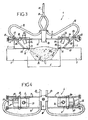
Les
La tringlerie 7 se compose de deux tiges rectilignes parallèles 16 et 17, tenues par un support central commun 18. Sur ces tiges 16 et 17 sont montés coulissants, de part et d'autre du support central 18, deux axes transversaux 19 et 20. Le premier axe transversal 19 sert de support au traducteur 5 et le second axe transversal 20 sert de support à l'autre traducteur 6, la disposition étant symétrique.The linkage 7 consists of two parallel
Chaque traducteur 5 ou 6 est ainsi monté mobile en translation le long des tiges 16 et 17 de la tringlerie 7, ce qui permet de régler l'écartement E entre les deux traducteurs 5 et 6.Each
De plus, l'inclinaison des deux traducteurs 5, 6 est réglable, par pivotement autour des axes respectifs 19 et 20. Des vis de blocage respectives 21 et 22 sont prévues pour l'immobilisation des deux traducteurs 5 et 6 dans les positions angulaires choisies.In addition, the inclination of the two
Dans le détail, chaque traducteur 5 ou 6 comprend :
- un corps 23 traversé par l'axe 19 ou 20, et pourvu d'un trou taraudé recevant la vis de blocage 21 ou 22 ;
un bloc 24 inséré dans le corps 23, et réunissant un élément piézoélectrique et son amortisseur ;- sur la face supérieure du corps 23, un connecteur 25 pour l'élément piézoélectrique 24 (pour le raccordement de la liaison 10 ou 12) ;
- sur la face inférieure du corps 23,
un point d'émergence 26 du faisceau ultrasonore ; - un raccord d'arrivée d'eau 27 relié, par un canal 28 interne au corps 23, à une sortie d'eau 29 située sur la face inférieure dudit corps 23.
- a body 23 traversed by the
axis 19 or 20, and provided with a threaded hole receiving the locking screw 21 or 22; - a
block 24 inserted in the body 23, and joining a piezoelectric element and its damper; - on the upper face of the body 23, a
connector 25 for the piezoelectric element 24 (for connecting the link 10 or 12); - on the lower face of the body 23, an
emergence point 26 of the ultrasound beam; - a water inlet connection 27 connected, via a channel 28 internal to the body 23, to a water outlet 29 situated on the underside of said body 23.
Par ailleurs, le système d'alimentation en eau sous pression 15 comporte un tube commun 30 aboutissant à un "Y" de répartition 31, d'où partent deux tubes souples 32, 33 qui aboutissent respectivement aux deux traducteurs 5, 6, plus particulièrement au raccord d'arrivée d'eau 27 de chaque traducteur. Ainsi est réalisé, au moyen d'une lame d'eau, le couplage acoustique entre chaque traducteur 5 ou 6 et l'élément à contrôler sur lequel est appliqué ce traducteur.Furthermore, the pressurized water supply system 15 comprises a
Les éléments piézoélectriques 24 des deux traducteurs 5 et 6 sont des céramiques piézoélectriques rectangulaires ou oblongues, par exemple de 6 x 4 mm, fonctionnant en ondes longitudinales avec faisceau acoustique pouvant aller de 30° à 80°, de préférence de 50° à 70°.The
Les fréquences de fonctionnement sont, quant à elles, comprises entre 1 et 20 MHz, de préférence entre 6 et 18 MHz, et plus préférentiellement encore entre 6.5 MHz et 8.5 MHz pour les épaisseurs de moins de 10 mm ou entre 15 et 20 MHz, de préférence de l'ordre de 18MHz pour les épaisseurs de moins de 10 mm, et/ou avec une largeur de bande associée de 75% ± 25% par rapport à la fréquence centrale à -6 dB.The operating frequencies are, for their part, between 1 and 20 MHz, preferably between 6 and 18 MHz, and even more preferably between 6.5 MHz and 8.5 MHz for thicknesses of less than 10 mm or between 15 and 20 MHz, preferably of the order of 18 MHz for thicknesses of less than 10 mm, and / or with an associated bandwidth of 75% ± 25% with respect to the center frequency at -6 dB.
On peut en fait utiliser des céramiques rectangulaires de longueur comprise entre 5 et 20 mm et de largeur comprise entre 2 et 8 mm.Rectangular ceramics with a length of between 5 and 20 mm and a width of between 2 and 8 mm can be used.
Utiliser des céramiques oblongues ou rectangulaires permet d'obtenir une forte divergence du faisceau ultrasonore et donc d'insonifier la totalité du volume à inspecter.Using oblong or rectangular ceramics makes it possible to obtain a strong divergence of the ultrasonic beam and thus to insonify the entire volume to be inspected.
On peut utiliser par exemple des traducteurs TOFD référencés 5-60 OL 55, commercialisés par la société METALSCAN.It is possible to use, for example, TOFD translators referenced 5-60
A titre d'exemple, un faisceau acoustique de 30 à 65° est utilisable pour inspecter des gammes d'épaisseur entre 10 et 300 mm. Un angle de réfraction dans l'acier de l'ordre de 53 à 58°, de préférence d'environ 55°, est ainsi recommandé pour une épaisseur de joint comprise entre 5 et 60 mm.By way of example, a sound beam of 30 to 65 ° can be used to inspect thickness ranges between 10 and 300 mm. A refraction angle in the steel of about 53 to 58 °, preferably about 55 °, is thus recommended for a joint thickness of between 5 and 60 mm.
En utilisation, comme l'illustre la figue 3, l'écartement E des deux traducteurs 5, 6, plus particulièrement de leurs points d'émergence 26 respectifs, est ajusté en fonction de la largeur et de l'épaisseur du joint soudé 1.In use, as illustrated in FIG. 3, the spacing E of the two
On a indiqué en I le trajet ultrasonore de l'onde latérale, et en II le trajet de l'écho de fond, le volume "insonifié" ayant été grisé.The ultrasonic path of the side wave is indicated in I, and the path of the background echo in II, the "insonified" volume having been greyed out.
Si une fissure 34 est présente dans ce volume, l'extrémité de la fissure 34 se comporte comme une source secondaire d'ondes sphériques (ondes diffractées).If a crack 34 is present in this volume, the end of the crack 34 behaves as a secondary source of spherical waves (diffracted waves).
On a encore indiqué en III le trajet ultrasonore de l'écho de diffraction, au sommet de la fissure 34.The ultrasonic path of the diffraction echo at the top of crack 34 has also been indicated in III.
L'analyse du signal reçu par le traducteur 6 récepteur, au cours du balayage du joint soudé 1, permet de déceler une telle fissure 34 et d'en mesurer la hauteur.Analysis of the signal received by the
En réception, un préamplificateur à pile de 24 dB peut être utilisé pour améliorer le rapport "signal sur bruit".In reception, a 24 dB battery preamplifier can be used to improve the signal-to-noise ratio.
La représentation des signaux reçus peut être notamment affichée en 14, en mode "B-SCAN redressé", c'est-à-dire avec un affichage du temps en fonction de l'amplitude du signal.The representation of the received signals can be notably displayed at 14, in "B-SCAN rectified" mode, that is to say with a display of the time as a function of the amplitude of the signal.
Comme l'illustre la
Enfin, comme illustré par la
Selon l'invention, il est très important de prévoir une phase d'étalonnage du ou des couples de traducteurs ultrasonores 5, 6, à partir d'une entaille électro-érodée de profondeur déterminée, simulant une fissure.According to the invention, it is very important to provide a phase of calibration of the pair or pairs of
En effet, sans cette étape préalable d'étalonnage, une détection efficace des fissures dans le joint peut être compromise.Indeed, without this prior calibration step, effective detection of cracks in the joint can be compromised.
Selon l'invention, la détection par la technique TOFD décrite ci-dessus est combinée avec une détection selon la technique dite OLI, pour Onde Longitudinale Inclinée, encore appelée technique d'ondes rampantes (Creeping Waves).According to the invention, the detection by the TOFD technique described above is combined with a detection according to the so-called OLI technique, for Longitudinal Inclined Wave, also called Creeping Waves technique.
En effet, une telle combinaison TOFD/OLI est particulièrement avantageuse car elle permet une détection efficace des fissures avec un appareil à 3 voies de contrôle, c'est-à-dire à trois traducteurs, et ce, non seulement des défauts, telles les fissures, de plus de 5 mm de profondeur mais aussi de celles de moins de 5 mm de profondeur qui sont parfois masquées par l'onde latérale, lors d'un examen en technique TOFD seule.Indeed, such a combination TOFD / OLI is particularly advantageous because it allows effective detection of cracks with a 3-way control device, that is to say three translators, and not only defects, such as cracks, more than 5 mm deep but also those less than 5 mm deep which are sometimes masked by the lateral wave, during a TOFD examination alone.
Pour ce faire, on utilise au moins 3 traducteurs de manière à couvrir totalement la totalité du volume insonifié.To do this, at least 3 translators are used to fully cover the entire insonified volume.
Toutefois, il est possible d'utiliser plus de 3 traducteurs de manière à affiner et/ou à améliorer encore davantage la détection, par exemple des traducteurs TOFD à angles différents ou des traducteurs à ondes transversales dites de "cisaillement".However, it is possible to use more than 3 translators so as to refine and / or further improve the detection, for example TOFD translators with different angles or so-called "shear" transverse wave translators.
Comme précédemment, l'analyse des signaux se fait alors par imagerie de type A-SCAN, B-SCAN, C-SCAN et/ou D-SCAN au moyen d'un système de filtrage, en temps réel ou différé, ou d'un système de calcul apte à extraire une caractérisation de l'indication mis en évidence. Préférentiellement, on utilise le logiciel VENUS de la société METALSCAN qui produit des représentations des signaux en mode B-SCAN ou D-SCAN à partir d'un signal haute fréquence (HF) ou le logiciel MIDAS de la société TECNATOM ou tout autre logiciel équivalent.As before, the analysis of the signals is then done by A-SCAN, B-SCAN, C-SCAN and / or D-SCAN type imagery by means of a filtering system, in real time or deferred, or of a calculation system capable of extracting a characterization of the indication highlighted. Preferably, the VENUS software from the company METALSCAN which produces representations of the signals in B-SCAN or D-SCAN mode from a high frequency signal (HF) or the MIDAS software from TECNATOM or any other equivalent software is used. .
Les composants fréquentielles des signaux enregistrés peuvent être, en outre, mesurés par analyse de la transformée de Fourrier.Frequency components of the recorded signals can be further measured by analysis of the Fourier transform.
En fait, la technique OLI permet de détecter les défauts de surface, débouchant ou non-débouchant à la surface, jusqu'à une profondeur allant, selon les cas, jusqu'à de 0.5 mm environ à 18 mm, ce qui permet de compléter efficacement la zone d'épaisseur dont l'examen ne s'avère pas toujours optimal avec la technique TOFD.In fact, the OLI technique makes it possible to detect surface defects, opening or non-opening on the surface, up to a depth ranging, depending on the case, from approximately 0.5 mm to 18 mm, which makes it possible to complete effectively the area of thickness whose examination is not always optimal with the TOFD technique.
Une telle combinaison des techniques TOFD/OLI n'a jamais été décrite jusqu'à présent et est particulièrement avantageuse au plan industriel et ce, d'autant plus qu'on précède l'examen d'une phase d'étalonnage, car cette combinaison TOFD/OLI permet de mettre en évidence des défauts de type volumique ou non-volumique dans les joints soudés sur la quasi-totalité de leur épaisseur, c'est-à-dire du volume insonifié, que ce soit à proximité de la surface (0.5 mm à 18 mm) ou plus en profondeur dans le joint (au-delà de 18 et jusqu'à 300 mm).Such a combination of TOFD / OLI techniques has never been described so far and is particularly advantageous at the industrial level, especially since it precedes the examination of a calibration phase, because this combination TOFD / OLI makes it possible to highlight defects of volumetric or non-voluminal type in the welded joints over almost all their thickness, that is to say of the insonified volume, that it is close to the surface ( 0.5 mm to 18 mm) or more in depth in the joint (beyond 18 and up to 300 mm).
En pratique, la taille minimale des discontinuités et autres fissures détectables efficacement par les techniques TOFD et OLI est de l'ordre de 0.5 mm, alors que la taille maximale correspond à une fissure traversante, c'est-à-dire selon toute l'épaisseur du joint.In practice, the minimum size of the discontinuities and other cracks detectable effectively by TOFD and OLI techniques is of the order of 0.5 mm, whereas the maximum size corresponds to a through crack, that is to say, all the way through. thickness of the joint.
Préférentiellement, la technique OLI est mise en oeuvre pour contrôler des fissures de moins de 5 mm, situées du côté de la face de sondage, par insonification avec des ondes longitudinales inclinées entre 70 et 90°, de préférence d'environ 76° d'angle de réfraction, et à une fréquence entre 1.5 et 4 MHz, par exemple de l'ordre de 2 MHz.Preferably, the OLI technique is used to control cracks of less than 5 mm, located on the side of the sounding face, by insonification with longitudinal waves inclined between 70 and 90 °, preferably about 76 °. angle of refraction, and at a frequency between 1.5 and 4 MHz, for example of the order of 2 MHz.
La ou les céramiques utilisées pour la mise en oeuvre de la technique OLI sont préférentiellement rectangulaires, par exemple de 5 x 10 mm, et les deux céramiques formant un traducteur fonctionnant en émission et réception séparée et/ou pour un ange de toit (roof angle) compris entre 5 et 15°, de préférence de l'ordre de 10°.The ceramic or ceramics used for the implementation of the OLI technique are preferably rectangular, for example 5 × 10 mm, and the two ceramics forming a translator operating in separate transmission and reception and / or for a roof angel ( roof angle ) between 5 and 15 °, preferably of the order of 10 °.
On peut utiliser des traducteurs standards de type FIDM 76-2 commercialisées par la société METALSCAN.Standard FIDM 76-2 type translators sold by METALSCAN can be used.
La
Le traducteur 57 se compose d'une céramique d'émission 53 d'ondes longitudinales et d'une céramique de réception 54 d'ondes sonores portées l'une et l'autre par un sabot 55 incliné, par exemple en plexiglas ou analogue, lequel forme un angle d'environ 27° (± 2°) avec la surface de la pièce dans le plan d'incidence.The
L'angle α de toit des céramiques 53, 54 est compris entre 5 et 15°, de préférence de l'ordre de 10°.The roof angle α of the
Les ondes sonores longitudinales réfractées sont envoyées dans le sens de la flèche F4 vers le joint de soudure 50 selon un angle β de l'ordre de 76° par rapport à la surface de la pièce.The refracted longitudinal sound waves are sent in the direction of the arrow F4 to the weld joint 50 at an angle β of the order of 76 ° relative to the surface of the workpiece.
L'angle γ est compris entre 26 et 29° et correspond à l'angle d'incidence de la semelle usinée en plexiglas.The angle γ is between 26 and 29 ° and corresponds to the angle of incidence of the plexiglass machined sole.
Comme montré sur la
Lorsque le joint 50 présente une largeur trop importante, on peut compléter l'inspection par des passages décalés en modes TOFD comme schématisé en
La
Plus précisément, pour inspecter de manière très efficace le joint 50, le procédé est mis en oeuvre en 5 passages ou balayages, à savoir :
- i) passage axial centré et le long du joint 50, en mode TOFD, avec traducteurs C-C,
- ii) passages décalés successivement à gauche puis à droite de l'axe du joint 50 (ou inversement), en mode TOFD, avec traducteurs A-A puis B-B
- iii) passage à gauche du joint 50, en mode OLI, avec traducteur OL1, et
- iv) passage à droite du joint, en mode OLI, avec traducteur OL2.
- i) axial passage centered and along the
seal 50, in TOFD mode, with DC translators, - ii) successively shifted passages to the left and then to the right of the axis of the seal 50 (or conversely), in TOFD mode, with translators AA then BB
- iii) passage to the left of the
seal 50, in OLI mode, with OL1 translator, and - iv) transition to the right of the joint, in OLI mode, with OL2 translator.
Les passages i) et ii) en mode TOFD se font avec des traducteurs A-A, B-B, C-C qui sont ici identiques ; les ondes étant envoyées sous un angle de 55° et à une fréquence de 7.5 MHz.Passes i) and ii) in TOFD mode are done with A-A, B-B, C-C translators which are identical here; the waves being sent at an angle of 55 ° and at a frequency of 7.5 MHz.
Les passages iii) et iv) en mode OLI se font avec des traducteurs OL1 et OL2 aussi identiques ; les ondes étant alors envoyées sous un angle de 76° et à une fréquence de 2 MHz (voir flèche F4).The passages iii) and iv) in OLI mode are done with translators OL1 and OL2 also identical; the waves are then sent at an angle of 76 ° and at a frequency of 2 MHz (see arrow F4).
Une telle séquence permet d'avoir une détection très efficace des fissures tant en longueur qu'en profondeur.Such a sequence makes it possible to have a very effective detection of cracks both in length and in depth.
Toutefois, il serait possible d'effectuer moins de passages, par exemple un seul passage axial en mode TOFD (passage i)) et un ou deux passages en mode OLI.However, it would be possible to perform fewer passes, for example a single axial passage in TOFD mode (passage i) and one or two passes in OLI mode.
Bien entendu, l'invention englobe toutes les variantes de réalisation et d'application respectant le principe ci-dessus, quels que soient notamment les détails constructifs du matériel de mise en oeuvre, par exemple au niveau de la structure de sa tringlerie, de la forme ou de la dimension des traducteurs. Par exemple, une focalisation électronique utilisant des traducteurs multi-éléments entrerait aussi dans le champ de l'invention.Of course, the invention encompasses all variants of implementation and application respecting the above principle, regardless of the particular constructive details of the implementation equipment, for example at the structure of its linkage, the form or dimension of the translators. For example, electronic focusing using multi-element translators would also fall within the scope of the invention.
Claims (15)
- Method for controlling welded joints (1, 50) using ultrasound, more particularly welded joints (1, 50) connecting two abutted metal parts (2, 3; 51, 52), wherein the control of the joint (1, 50) is carried outa) is moved, by applying the Time of Flight Differential Technique ("TOFD"), in the longitudinal or circumferential direction, in a single pass along the welded joint (1) to be controlled, at least one pair formed by a first translator (5) and by a second translator (6), one transmitter and one receiver of ultrasonic wave, said translators (5, 6) being positioned laterally on either side of the joint (1) to be controlled, said translators (5, 6) comprising piezoelectric ceramics or crystals, so as to detect any flaw in the joint (1, 50) located at a thickness of at least 10 mm.b) is moved in a single pass along the weld joint (1) to be controlled, by applying the inclined longitudinal wave ("OLI") technique which is implemented by insonification of at least one portion of the joint (1, 50) to be controlled with longitudinal sound waves inclined by an angle (β) between 70° and 90° of an angle of refraction, at least one third translator (57, 53, 54, 55), in such a way as to detect any defect in the joint (1, 50) located at a thickness of between 0.5 mm and 15 mm.
- Method according to claim 1, characterised in that in the step a), the first and second translators (5, 6) comprise piezoelectric ceramics or crystals of rectangular or oblong shape (24).
- Method according to one of claims 1 or 2, characterised in that in step a), the ultrasonic translators (5, 6) have a frequency band higher than 60% of the centre frequency and a frequency between 1 and 20 MHz, preferably between 6 and 18 MHz.
- Method according to one of claims 1 to 3, characterised in that it comprises the lateral offset (D) of the pair of ultrasonic translators (5, 6), with respect to the centre or to the axis of the weld joint (1, 50).
- Method according to one of claims 1 to 4, characterised in that in step a), any flaw in the joint (1, 50) is detected located at a thickness between 10 and 300 mm, preferably between 10 and 60 mm.
- Method according to claim 1, characterised in that in step b), the "OLI" technique is implemented by insonifying at least one portion of the joint (1, 50) to be controlled with longitudinal sound waves inclined at an angle (β) of about 76° of angle of refraction, and/or at a frequency between 1.5 and 4 MHz, in particular about 2 MHz.
- Method according to one of claims 1 or 6, characterised in that step b) is carried out in succession on each side of the weld joint (1, 50) to be controlled.
- Method according to one of claims 1, 6 or 7, characterised in that in step b), any defect of the joint is detected (1, 50) located at a thickness between 0.5 mm and 20 mm, preferably from 0.5 mm to 10 mm.
- Method according to one of claims 1, 6 to 8, characterised in that in step b), at least one third translator (57, 53, 54, 55) is used comprising a wave transmitting ceramic (53) making it possible to emit sound waves in the direction of the weld (1, 50) and an ultrasound wave receiving ceramic (54) making it possible to receive ultrasonic waves.
- Method according to one of claims 1 to 9, characterised in that it comprises a calibration phase of the pair or pairs of ultrasonic translators (5, 6), from a calibration notch with a determined depth, simulating a crack, preferably a notch with a length equal to 10 mm and a depth of about 1 mm.
- Method according to one of claims 1 to 10, characterised in that it comprises at least one step of analysing at least one signal received by one or each receiving translator, during scanning of the weld joint (1, 50), so as to detect any flaw, in particular any crack (34), and preferably to determine or evaluate the height or dimension thereof.
- Method according to one of claims 1 to 11, characterised in that the thickness (e) is between 5 mm and at least 60 mm, and the parts are walls of equipment or components that operate under pressure, belonging to chemical or petrochemical units, nuclear power plants or similar, flying machines structures, elements or parts of rotating machines, pipes, railroad rails or any other mechanically-welded unit.
- Equipment for the implementation of the method of controlling weld joints according to any one of claims 1 to 12, characterised in that it comprises:- at least one pair formed from a first and second translators (5, 6), one transmitter and the other a receiver of ultrasonic wave receiver, said translators (5, 6) being positioned laterally on either side of the joint (1) to be controlled and arranged in such a way as to be able to apply the TOFD technique by displacement in the longitudinal or circumferential direction, along the weld joint to be controlled in such a way as to detect any flaw of the joint (1, 50) located at a thickness of at least 10 mm in a single pass, with the two translators (5, 6) using piezoelectric ceramics or crystals (24), and the two translators (5, 6) being mechanically connected by a common support (7) comprising a linkage (16, 17) arranged to enable adjustment of the spacing (E) between these two ultrasonic translators (5, 6), a pivot mounting (axes 19, 20) of each translator (5, 6), with locking means (21, 22) in a selected angular position, and also being connected to an inlet (15, 30 to 33) of liquid, in particular of water, for the acoustic coupling of these translators (5, 6) with the element to be controlled (1, 2, 3),- at least one third translator (57, 53, 54, 55) arranged in such a way as to be able to apply the inclined longitudinal wave ("OLI") technique which is implemented by insonification of at least one portion of the joint (1, 50) to be controlled with longitudinal sound waves inclined by an angle (β) between 70° and 90° of an angle of refraction and by displacement along the weld joint (1) to be controlled, in such a way as to detect any flaw of the joint (1, 50) located at a thickness between 0.5 mm and 15 mm, and- means for processing (8) measurements, with the translators still being connected to said means of processing (8) measurements.
- Equipment according to claim 13, characterised in that the common support (7) of the two ultrasonic translators (5, 6) has an assembly allowing for an lateral offset (D) of the pair of translators (5,6) with respect to the centre of the weld joint (1) to be controlled.
- Equipment according to claim 13, characterised in that said third translator (57, 53, 54, 55) comprises a wave transmitting ceramic (53) making it possible to emit sound waves and a sound wave receiving ceramic (54) making it possible to receive sound waves.
Applications Claiming Priority (3)
| Application Number | Priority Date | Filing Date | Title |
|---|---|---|---|
| FR0207441 | 2002-06-17 | ||
| FR0207441A FR2840991B1 (en) | 2002-06-17 | 2002-06-17 | ULTRASONIC CONTROL METHOD FOR WELDED JOINTS |
| PCT/FR2003/001798 WO2003106994A1 (en) | 2002-06-17 | 2003-06-13 | Method for ultrasonic control of weld joints |
Publications (2)
| Publication Number | Publication Date |
|---|---|
| EP1516178A1 EP1516178A1 (en) | 2005-03-23 |
| EP1516178B1 true EP1516178B1 (en) | 2015-12-09 |
Family
ID=29595308
Family Applications (1)
| Application Number | Title | Priority Date | Filing Date |
|---|---|---|---|
| EP03760034.3A Expired - Lifetime EP1516178B1 (en) | 2002-06-17 | 2003-06-13 | Method for ultrasonic control of weld joints |
Country Status (5)
| Country | Link |
|---|---|
| US (1) | US7168322B2 (en) |
| EP (1) | EP1516178B1 (en) |
| AU (1) | AU2003263235A1 (en) |
| FR (1) | FR2840991B1 (en) |
| WO (1) | WO2003106994A1 (en) |
Families Citing this family (39)
| Publication number | Priority date | Publication date | Assignee | Title |
|---|---|---|---|---|
| NL1024726C2 (en) * | 2003-11-06 | 2005-05-09 | Roentgen Tech Dienst Bv | Method for checking a weld between two metal pipelines. |
| MD2839C2 (en) * | 2004-11-05 | 2006-05-31 | Андрей Аким ТКАЧЕНКО | Method of welds ultrasonic testing |
| US8183493B2 (en) * | 2005-09-28 | 2012-05-22 | General Electric Company | Ultrasonic system for monitoring a weld operation |
| JP4910770B2 (en) * | 2007-02-28 | 2012-04-04 | Jfeスチール株式会社 | Tubular ultrasonic inspection apparatus and ultrasonic inspection method |
| JP4839333B2 (en) * | 2008-03-19 | 2011-12-21 | 日立Geニュークリア・エナジー株式会社 | Ultrasonic inspection method and ultrasonic inspection apparatus |
| US20090283569A1 (en) * | 2008-05-13 | 2009-11-19 | General Electric Company | System and method for monitoring welding |
| US8746069B2 (en) * | 2008-10-20 | 2014-06-10 | Fluor Technologies Corporation | Devices and methods of ultrasound time of flight diffraction sensitivity demonstration |
| US20100169053A1 (en) * | 2008-12-30 | 2010-07-01 | Caterpillar Inc. | Method for creating weldment inspection documents |
| US7900517B2 (en) * | 2009-06-16 | 2011-03-08 | Rontgen Technische Dienst B.V. | System and method for inspecting a pipeline with ultrasound |
| NL2003154C2 (en) * | 2009-07-08 | 2011-01-11 | R0Ntgen Tech Dienst B V | Method for ultrasonic sizing. |
| CN102869987B (en) * | 2010-04-23 | 2016-04-20 | 西门子奥钢联冶金技术有限公司 | The ultrasonic detection method of the butt-weld of two transverse end of two sheet metal strips and equipment |
| US20120091185A1 (en) * | 2010-10-18 | 2012-04-19 | Georgia Tech Research Corporation | In-process weld geometry methods & systems |
| DK2633302T3 (en) * | 2011-01-11 | 2014-10-20 | Siemens Ag | Method for determining the fiber direction in a rotor blade of a wind turbine having a plurality of fibers distributed in a laminate material |
| CA2806482A1 (en) * | 2011-02-03 | 2012-08-09 | Absolute Nde International Inc. | Method for ultrasonic inspection of welds |
| JP5733504B2 (en) * | 2011-03-09 | 2015-06-10 | 株式会社Ihi | Defect detection method for welds |
| DE102011109717B3 (en) * | 2011-08-06 | 2012-10-11 | Ndt Systems & Services Gmbh & Co. Kg | Method and sensor carrier for roofing measurement of pipes by ultrasonic testing |
| CN102435674B (en) * | 2011-09-16 | 2013-03-27 | 国家电网公司 | A method for detecting cracks and corrosion defects on the inner wall of base metal of metal parts |
| FR2984507B1 (en) | 2011-12-16 | 2017-02-17 | Soudure Inst De | NON-DESTRUCTIVE ULTRASONIC CONTROL DEVICE |
| US9261490B2 (en) * | 2012-03-29 | 2016-02-16 | J. Ray Mcdermott, S.A. | Ultrasonic transducer arrangement |
| US20130268214A1 (en) * | 2012-04-04 | 2013-10-10 | Siemens Aktiengesellschaft | Probabilistic fatigue life prediction using ultrasonic inspection data considering eifs uncertainty |
| EP2906906A1 (en) * | 2012-10-15 | 2015-08-19 | Shell Internationale Research Maatschappij B.V. | A method of locating and sizing fatigue cracks |
| WO2014088929A1 (en) * | 2012-12-03 | 2014-06-12 | United Technologies Corporation | A method of fabricating a rotor of a turbofan engine |
| US9207214B2 (en) * | 2013-04-30 | 2015-12-08 | General Electric Company | Auto beam optimization for phased array weld inspection |
| FR3011332B1 (en) * | 2013-09-30 | 2019-12-20 | Areva Np | METHOD AND DEVICE FOR NON-DESTRUCTIVE TESTING OF A WELDING OF A NUCLEAR REACTOR PART |
| EP2963380B2 (en) * | 2014-07-04 | 2025-06-25 | Georg Fischer Rohrleitungssysteme AG | Contactless inspection for butt welding |
| KR101658122B1 (en) * | 2015-05-07 | 2016-09-21 | (주)피앤에스 | Method and apparatus for displaying on a screen the state of welded sections measured using ultrasonic waves |
| CN104931582A (en) * | 2015-06-16 | 2015-09-23 | 南车青岛四方机车车辆股份有限公司 | Thin plate overlap joint narrow weld joint ultrasound fast nondestructive testing method and device |
| JP6703297B2 (en) * | 2015-10-14 | 2020-06-03 | 日本製鉄株式会社 | Tandem flaw detection jig and tandem flaw detection method |
| GB201803062D0 (en) | 2018-02-26 | 2018-04-11 | Gb Inspection Systems Ltd | Ultrasonic probe |
| JP7094192B2 (en) * | 2018-10-17 | 2022-07-01 | 日立Geニュークリア・エナジー株式会社 | Ultrasonography system |
| CN110554089B (en) * | 2019-09-09 | 2022-04-01 | 西安特种设备检验检测院 | Method, device, equipment and storage medium for detecting welding joint |
| RU2740168C1 (en) * | 2020-03-20 | 2021-01-12 | Общество с ограниченной ответственностью "Научно-производственный центр неразрушающего контроля "ЭХО+" | Method of determining reflector coordinate in section perpendicular to welded connection based on tofd-echo signals |
| US11573208B2 (en) * | 2020-03-31 | 2023-02-07 | Olympus NDT Canada Inc. | Longitudinal and circumferential ultrasound scanner |
| USD1103806S1 (en) | 2020-10-22 | 2025-12-02 | Evident Canada, Inc. | Scanner frame |
| US20220146460A1 (en) * | 2020-11-11 | 2022-05-12 | Southwest Research Institute | Guided wave testing of welds in pipelines and plate structures |
| CN112834616B (en) * | 2021-01-04 | 2022-10-14 | 中车青岛四方机车车辆股份有限公司 | Welding seam detection device and method |
| WO2023025368A1 (en) * | 2021-08-23 | 2023-03-02 | NDT Global Corporate Ltd. Ireland | Determination of peaking in pipes |
| CN113533534B (en) * | 2021-08-31 | 2025-03-21 | 上海地铁维护保障有限公司 | A high-precision weld defect detection device |
| FR3149693A1 (en) * | 2023-06-06 | 2024-12-13 | Onet Technologies Cn | method and device for non-destructive ultrasonic testing of a metal part or a weld bead |
Family Cites Families (23)
| Publication number | Priority date | Publication date | Assignee | Title |
|---|---|---|---|---|
| US3201864A (en) * | 1960-11-25 | 1965-08-24 | Sonobond Corp | Method and apparatus for ultrasonic welding |
| US3302453A (en) * | 1963-04-15 | 1967-02-07 | American Mach & Foundry | Method of inspection utilizing ultrasonic energy |
| US3332278A (en) * | 1963-07-15 | 1967-07-25 | American Mach & Foundry | Ultrasonic flaw detection |
| US3436958A (en) * | 1965-10-11 | 1969-04-08 | American Mach & Foundry | Ultrasonic pipe testing method and apparatus |
| US3540267A (en) * | 1967-10-18 | 1970-11-17 | American Mach & Foundry | Ultrasonic testing of drill pipe and the like |
| US3868847A (en) * | 1972-12-04 | 1975-03-04 | Walter A Gunkel | System and apparatus for inspecting elongated welds |
| DE2613799C2 (en) * | 1976-03-29 | 1979-11-22 | Mannesmann Ag, 4000 Duesseldorf | Procedure for setting up ultrasonic testing systems |
| FR2566536B1 (en) | 1984-06-25 | 1987-10-02 | Cence Mario | VERSATILE ULTRASONIC TRANSLATOR ADAPTABLE TO EXAM CONFIGURATIONS |
| GB2195022B (en) * | 1986-09-08 | 1990-11-28 | Atomic Energy Authority Uk | Ultrasonic scanning apparatus |
| GB8628662D0 (en) * | 1986-12-01 | 1987-01-07 | Atomic Energy Authority Uk | Ultrasonic scanning apparatus |
| GB8714002D0 (en) * | 1987-06-16 | 1987-07-22 | Atomic Energy Authority Uk | Ultrasonic transducer |
| DE3725658A1 (en) * | 1987-08-03 | 1989-02-16 | Hoesch Ag | METHOD AND DEVICE FOR CONNECTING AN ULTRASONIC TEST HEAD TO A TESTING PART |
| US5677490A (en) * | 1993-02-18 | 1997-10-14 | F. H. Gottfeld Gesellschaft Fur Zerstorungsfreie Werkstoffprufung Mbh | Ultrasonic testing device for weld seams in pipes, sheets and containers |
| US5804730A (en) * | 1995-10-10 | 1998-09-08 | Pfannenstiel; Richard A. | Ultrasonic testing method |
| FR2750502B1 (en) | 1996-06-27 | 1998-08-21 | Jeumont Ind | DEVICE AND METHOD FOR ULTRASONIC CONTROL OF A PART OF HIGH THICKNESS |
| US5814731A (en) * | 1997-01-28 | 1998-09-29 | Alexander; Alton Michel | Ultrasonic scanning apparatus for nondestructive site characterization of structures using a planar based acoustic transmitter and receiver in a rolling pond |
| JPH11108902A (en) * | 1997-09-30 | 1999-04-23 | Mitsubishi Heavy Ind Ltd | Detection of flaw of pipe by two probes |
| US6125704A (en) * | 1998-01-16 | 2000-10-03 | Shell Oil Company | Ultrasonic technique for inspection of weld and heat-affected zone for localized high temperature hydrogen attack |
| NO994984L (en) * | 1998-10-14 | 2000-04-17 | Daido Steel Co Ltd | Method for determining joint properties of a metal pipe |
| JP2001296282A (en) * | 2000-04-12 | 2001-10-26 | Hatsuden Setsubi Gijutsu Kensa Kyokai | Method and apparatus for visualizing elastic wave propagation in solid |
| US6405596B1 (en) | 2000-10-13 | 2002-06-18 | Chicago Bridge & Iron Company | Ultrasonic austenitic weld seam inspection method and apparatus |
| US6684706B2 (en) * | 2000-11-29 | 2004-02-03 | Cooper Cameron Corporation | Ultrasonic testing system |
| US7093490B2 (en) * | 2004-02-23 | 2006-08-22 | Hitachi, Ltd. | Ultrasonic flaw detecting method and ultrasonic flaw detector |
-
2002
- 2002-06-17 FR FR0207441A patent/FR2840991B1/en not_active Expired - Fee Related
-
2003
- 2003-06-13 WO PCT/FR2003/001798 patent/WO2003106994A1/en not_active Ceased
- 2003-06-13 AU AU2003263235A patent/AU2003263235A1/en not_active Abandoned
- 2003-06-13 US US10/518,139 patent/US7168322B2/en not_active Expired - Lifetime
- 2003-06-13 EP EP03760034.3A patent/EP1516178B1/en not_active Expired - Lifetime
Also Published As
| Publication number | Publication date |
|---|---|
| FR2840991B1 (en) | 2005-05-06 |
| WO2003106994A1 (en) | 2003-12-24 |
| US20050223807A1 (en) | 2005-10-13 |
| FR2840991A1 (en) | 2003-12-19 |
| US7168322B2 (en) | 2007-01-30 |
| EP1516178A1 (en) | 2005-03-23 |
| AU2003263235A1 (en) | 2003-12-31 |
Similar Documents
| Publication | Publication Date | Title |
|---|---|---|
| EP1516178B1 (en) | Method for ultrasonic control of weld joints | |
| EP0204143B1 (en) | Method and apparatus for the ultrasonic detection of internal faults in the edges of the head of a railway rail | |
| EP2158479B1 (en) | Method and apparatus for the automatic non-destructive inspection of tubular axle pins having variable inside and outside radius profiles | |
| EP2401606A1 (en) | A method for testing pipeline welds using ultrasonic phased arrays | |
| US20060130586A1 (en) | Configurations and methods for ultrasound time of flight diffraction analysis | |
| CA3108506C (en) | Multi-element ultrasound interior line examination device | |
| CA2390712A1 (en) | Method for inspecting clad pipe | |
| JP7156912B2 (en) | Ultrasonic inspection of structures with lamps | |
| NL1024726C2 (en) | Method for checking a weld between two metal pipelines. | |
| EP0099816B1 (en) | Method and apparatus for ultrasonic echography | |
| FR2984507A1 (en) | NON-DESTRUCTIVE ULTRASONIC CONTROL DEVICE | |
| WO2024121512A1 (en) | Method for detecting cracks in a tubular pipe | |
| Casula et al. | Ultrasonic nondestructive testing of complex components with flexible phased-array transducers | |
| CA2780329A1 (en) | System including a non-destructive wheel sensor measurement device, related wheel-sensor and inspection method | |
| JP2001330594A (en) | Inspection method of metal pipe joint | |
| Hesse et al. | Defect detection in rails using ultrasonic surface waves | |
| EP3289348B1 (en) | Method for controlling welds by ultrasound | |
| EP1705483B1 (en) | Determination of the expanse of a lateral shadow area in a method of ultrasound testing | |
| WO2001071339A1 (en) | Method for assessing resilience of a welded assembly and corresponding analysis apparatus for measuring surface ultrasonic wave speeds | |
| WO2026002920A1 (en) | Method and assembly for ultrasonic inspection of a pipe | |
| JP2001165916A (en) | Pencil type local water immersion ultrasonic probe and method for detecting flaws in welds using the same | |
| Hörchens et al. | Adaptive ultrasonic imaging of electric resistance welded pipeline seams | |
| FR2937136A1 (en) | NON-DESTRUCTIVE CONTROL METHOD USING LAMB WAVES FOR DETERMINING ZONES OF A STRUCTURE COMPRISING DEFECTS | |
| Na et al. | Assessment of weld quality of aerospace grade metals by using ultrasonic matrix phased array technology | |
| Sicard et al. | Phased Array Scanner Head for Train Axle Inspection |
Legal Events
| Date | Code | Title | Description |
|---|---|---|---|
| PUAI | Public reference made under article 153(3) epc to a published international application that has entered the european phase |
Free format text: ORIGINAL CODE: 0009012 |
|
| 17P | Request for examination filed |
Effective date: 20050117 |
|
| AK | Designated contracting states |
Kind code of ref document: A1 Designated state(s): AT BE BG CH CY CZ DE DK EE ES FI FR GB GR HU IE IT LI LU MC NL PT RO SE SI SK TR |
|
| AX | Request for extension of the european patent |
Extension state: AL LT LV MK |
|
| DAX | Request for extension of the european patent (deleted) | ||
| RAP1 | Party data changed (applicant data changed or rights of an application transferred) |
Owner name: L'AIR LIQUIDE, SOCIETE ANONYME POUR L'ETUDE ET L'E |
|
| RAP1 | Party data changed (applicant data changed or rights of an application transferred) |
Owner name: L'AIR LIQUIDE, SOCIETE ANONYME POUR L'ETUDE ET L'E |
|
| 17Q | First examination report despatched |
Effective date: 20071123 |
|
| REG | Reference to a national code |
Ref country code: DE Ref legal event code: R079 Ref document number: 60348332 Country of ref document: DE Free format text: PREVIOUS MAIN CLASS: G01N0029260000 Ipc: G01N0029040000 |
|
| RIC1 | Information provided on ipc code assigned before grant |
Ipc: G01N 29/26 20060101ALI20130417BHEP Ipc: G01N 29/04 20060101AFI20130417BHEP Ipc: G01N 29/06 20060101ALI20130417BHEP Ipc: B23K 31/12 20060101ALI20130417BHEP |
|
| GRAP | Despatch of communication of intention to grant a patent |
Free format text: ORIGINAL CODE: EPIDOSNIGR1 |
|
| INTG | Intention to grant announced |
Effective date: 20150702 |
|
| GRAS | Grant fee paid |
Free format text: ORIGINAL CODE: EPIDOSNIGR3 |
|
| GRAA | (expected) grant |
Free format text: ORIGINAL CODE: 0009210 |
|
| AK | Designated contracting states |
Kind code of ref document: B1 Designated state(s): AT BE BG CH CY CZ DE DK EE ES FI FR GB GR HU IE IT LI LU MC NL PT RO SE SI SK TR |
|
| REG | Reference to a national code |
Ref country code: GB Ref legal event code: FG4D Free format text: NOT ENGLISH |
|
| REG | Reference to a national code |
Ref country code: AT Ref legal event code: REF Ref document number: 764800 Country of ref document: AT Kind code of ref document: T Effective date: 20151215 Ref country code: CH Ref legal event code: EP |
|
| REG | Reference to a national code |
Ref country code: IE Ref legal event code: FG4D Free format text: LANGUAGE OF EP DOCUMENT: FRENCH |
|
| REG | Reference to a national code |
Ref country code: DE Ref legal event code: R096 Ref document number: 60348332 Country of ref document: DE |
|
| REG | Reference to a national code |
Ref country code: NL Ref legal event code: MP Effective date: 20151209 |
|
| PG25 | Lapsed in a contracting state [announced via postgrant information from national office to epo] |
Ref country code: ES Free format text: LAPSE BECAUSE OF FAILURE TO SUBMIT A TRANSLATION OF THE DESCRIPTION OR TO PAY THE FEE WITHIN THE PRESCRIBED TIME-LIMIT Effective date: 20151209 |
|
| REG | Reference to a national code |
Ref country code: AT Ref legal event code: MK05 Ref document number: 764800 Country of ref document: AT Kind code of ref document: T Effective date: 20151209 |
|
| PG25 | Lapsed in a contracting state [announced via postgrant information from national office to epo] |
Ref country code: SE Free format text: LAPSE BECAUSE OF FAILURE TO SUBMIT A TRANSLATION OF THE DESCRIPTION OR TO PAY THE FEE WITHIN THE PRESCRIBED TIME-LIMIT Effective date: 20151209 Ref country code: GR Free format text: LAPSE BECAUSE OF FAILURE TO SUBMIT A TRANSLATION OF THE DESCRIPTION OR TO PAY THE FEE WITHIN THE PRESCRIBED TIME-LIMIT Effective date: 20160310 Ref country code: FI Free format text: LAPSE BECAUSE OF FAILURE TO SUBMIT A TRANSLATION OF THE DESCRIPTION OR TO PAY THE FEE WITHIN THE PRESCRIBED TIME-LIMIT Effective date: 20151209 Ref country code: NL Free format text: LAPSE BECAUSE OF FAILURE TO SUBMIT A TRANSLATION OF THE DESCRIPTION OR TO PAY THE FEE WITHIN THE PRESCRIBED TIME-LIMIT Effective date: 20151209 |
|
| REG | Reference to a national code |
Ref country code: FR Ref legal event code: PLFP Year of fee payment: 14 |
|
| PG25 | Lapsed in a contracting state [announced via postgrant information from national office to epo] |
Ref country code: IT Free format text: LAPSE BECAUSE OF FAILURE TO SUBMIT A TRANSLATION OF THE DESCRIPTION OR TO PAY THE FEE WITHIN THE PRESCRIBED TIME-LIMIT Effective date: 20151209 Ref country code: CZ Free format text: LAPSE BECAUSE OF FAILURE TO SUBMIT A TRANSLATION OF THE DESCRIPTION OR TO PAY THE FEE WITHIN THE PRESCRIBED TIME-LIMIT Effective date: 20151209 |
|
| PGFP | Annual fee paid to national office [announced via postgrant information from national office to epo] |
Ref country code: DE Payment date: 20160621 Year of fee payment: 14 |
|
| PG25 | Lapsed in a contracting state [announced via postgrant information from national office to epo] |
Ref country code: PT Free format text: LAPSE BECAUSE OF FAILURE TO SUBMIT A TRANSLATION OF THE DESCRIPTION OR TO PAY THE FEE WITHIN THE PRESCRIBED TIME-LIMIT Effective date: 20160411 Ref country code: SK Free format text: LAPSE BECAUSE OF FAILURE TO SUBMIT A TRANSLATION OF THE DESCRIPTION OR TO PAY THE FEE WITHIN THE PRESCRIBED TIME-LIMIT Effective date: 20151209 Ref country code: AT Free format text: LAPSE BECAUSE OF FAILURE TO SUBMIT A TRANSLATION OF THE DESCRIPTION OR TO PAY THE FEE WITHIN THE PRESCRIBED TIME-LIMIT Effective date: 20151209 Ref country code: EE Free format text: LAPSE BECAUSE OF FAILURE TO SUBMIT A TRANSLATION OF THE DESCRIPTION OR TO PAY THE FEE WITHIN THE PRESCRIBED TIME-LIMIT Effective date: 20151209 Ref country code: RO Free format text: LAPSE BECAUSE OF FAILURE TO SUBMIT A TRANSLATION OF THE DESCRIPTION OR TO PAY THE FEE WITHIN THE PRESCRIBED TIME-LIMIT Effective date: 20151209 |
|
| PGFP | Annual fee paid to national office [announced via postgrant information from national office to epo] |
Ref country code: FR Payment date: 20160627 Year of fee payment: 14 |
|
| REG | Reference to a national code |
Ref country code: DE Ref legal event code: R097 Ref document number: 60348332 Country of ref document: DE |
|
| PLBE | No opposition filed within time limit |
Free format text: ORIGINAL CODE: 0009261 |
|
| STAA | Information on the status of an ep patent application or granted ep patent |
Free format text: STATUS: NO OPPOSITION FILED WITHIN TIME LIMIT |
|
| PG25 | Lapsed in a contracting state [announced via postgrant information from national office to epo] |
Ref country code: DK Free format text: LAPSE BECAUSE OF FAILURE TO SUBMIT A TRANSLATION OF THE DESCRIPTION OR TO PAY THE FEE WITHIN THE PRESCRIBED TIME-LIMIT Effective date: 20151209 |
|
| 26N | No opposition filed |
Effective date: 20160912 |
|
| PG25 | Lapsed in a contracting state [announced via postgrant information from national office to epo] |
Ref country code: SI Free format text: LAPSE BECAUSE OF FAILURE TO SUBMIT A TRANSLATION OF THE DESCRIPTION OR TO PAY THE FEE WITHIN THE PRESCRIBED TIME-LIMIT Effective date: 20151209 |
|
| PG25 | Lapsed in a contracting state [announced via postgrant information from national office to epo] |
Ref country code: BE Free format text: LAPSE BECAUSE OF NON-PAYMENT OF DUE FEES Effective date: 20160630 |
|
| PG25 | Lapsed in a contracting state [announced via postgrant information from national office to epo] |
Ref country code: MC Free format text: LAPSE BECAUSE OF FAILURE TO SUBMIT A TRANSLATION OF THE DESCRIPTION OR TO PAY THE FEE WITHIN THE PRESCRIBED TIME-LIMIT Effective date: 20151209 |
|
| REG | Reference to a national code |
Ref country code: CH Ref legal event code: PL |
|
| GBPC | Gb: european patent ceased through non-payment of renewal fee |
Effective date: 20160613 |
|
| REG | Reference to a national code |
Ref country code: IE Ref legal event code: MM4A |
|
| PG25 | Lapsed in a contracting state [announced via postgrant information from national office to epo] |
Ref country code: CH Free format text: LAPSE BECAUSE OF NON-PAYMENT OF DUE FEES Effective date: 20160630 Ref country code: LI Free format text: LAPSE BECAUSE OF NON-PAYMENT OF DUE FEES Effective date: 20160630 |
|
| PG25 | Lapsed in a contracting state [announced via postgrant information from national office to epo] |
Ref country code: IE Free format text: LAPSE BECAUSE OF NON-PAYMENT OF DUE FEES Effective date: 20160613 Ref country code: GB Free format text: LAPSE BECAUSE OF NON-PAYMENT OF DUE FEES Effective date: 20160613 |
|
| REG | Reference to a national code |
Ref country code: DE Ref legal event code: R119 Ref document number: 60348332 Country of ref document: DE |
|
| REG | Reference to a national code |
Ref country code: FR Ref legal event code: ST Effective date: 20180228 |
|
| PG25 | Lapsed in a contracting state [announced via postgrant information from national office to epo] |
Ref country code: DE Free format text: LAPSE BECAUSE OF NON-PAYMENT OF DUE FEES Effective date: 20180103 |
|
| PG25 | Lapsed in a contracting state [announced via postgrant information from national office to epo] |
Ref country code: FR Free format text: LAPSE BECAUSE OF NON-PAYMENT OF DUE FEES Effective date: 20170630 Ref country code: CY Free format text: LAPSE BECAUSE OF FAILURE TO SUBMIT A TRANSLATION OF THE DESCRIPTION OR TO PAY THE FEE WITHIN THE PRESCRIBED TIME-LIMIT Effective date: 20151209 Ref country code: HU Free format text: LAPSE BECAUSE OF FAILURE TO SUBMIT A TRANSLATION OF THE DESCRIPTION OR TO PAY THE FEE WITHIN THE PRESCRIBED TIME-LIMIT; INVALID AB INITIO Effective date: 20030613 |
|
| PG25 | Lapsed in a contracting state [announced via postgrant information from national office to epo] |
Ref country code: LU Free format text: LAPSE BECAUSE OF NON-PAYMENT OF DUE FEES Effective date: 20160613 Ref country code: TR Free format text: LAPSE BECAUSE OF FAILURE TO SUBMIT A TRANSLATION OF THE DESCRIPTION OR TO PAY THE FEE WITHIN THE PRESCRIBED TIME-LIMIT Effective date: 20151209 |
|
| PG25 | Lapsed in a contracting state [announced via postgrant information from national office to epo] |
Ref country code: BG Free format text: LAPSE BECAUSE OF FAILURE TO SUBMIT A TRANSLATION OF THE DESCRIPTION OR TO PAY THE FEE WITHIN THE PRESCRIBED TIME-LIMIT Effective date: 20151209 |