EP1515894B1 - Installation servant a emballer une bande souple disposee en couches de boucles en zigzag, en particulier d'une bande textile - Google Patents
Installation servant a emballer une bande souple disposee en couches de boucles en zigzag, en particulier d'une bande textile Download PDFInfo
- Publication number
- EP1515894B1 EP1515894B1 EP03727120A EP03727120A EP1515894B1 EP 1515894 B1 EP1515894 B1 EP 1515894B1 EP 03727120 A EP03727120 A EP 03727120A EP 03727120 A EP03727120 A EP 03727120A EP 1515894 B1 EP1515894 B1 EP 1515894B1
- Authority
- EP
- European Patent Office
- Prior art keywords
- web
- loop
- loops
- loop arrangement
- moved
- Prior art date
- Legal status (The legal status is an assumption and is not a legal conclusion. Google has not performed a legal analysis and makes no representation as to the accuracy of the status listed.)
- Expired - Lifetime
Links
- 238000004806 packaging method and process Methods 0.000 title claims abstract description 41
- 239000004753 textile Substances 0.000 title claims description 8
- 238000012546 transfer Methods 0.000 claims abstract description 37
- 238000006073 displacement reaction Methods 0.000 claims description 14
- 238000012856 packing Methods 0.000 claims description 11
- 238000013461 design Methods 0.000 claims description 5
- 238000012858 packaging process Methods 0.000 abstract description 2
- 230000005540 biological transmission Effects 0.000 description 4
- 239000000463 material Substances 0.000 description 3
- 238000000926 separation method Methods 0.000 description 3
- 238000000034 method Methods 0.000 description 2
- 230000002093 peripheral effect Effects 0.000 description 2
- 238000012545 processing Methods 0.000 description 2
- 230000035939 shock Effects 0.000 description 2
- 238000012549 training Methods 0.000 description 2
- 230000037303 wrinkles Effects 0.000 description 2
- 239000002390 adhesive tape Substances 0.000 description 1
- 230000015572 biosynthetic process Effects 0.000 description 1
- 239000007795 chemical reaction product Substances 0.000 description 1
- 230000003750 conditioning effect Effects 0.000 description 1
- 230000001419 dependent effect Effects 0.000 description 1
- 238000007788 roughening Methods 0.000 description 1
- 230000035945 sensitivity Effects 0.000 description 1
- 239000007787 solid Substances 0.000 description 1
Images


Classifications
-
- B—PERFORMING OPERATIONS; TRANSPORTING
- B65—CONVEYING; PACKING; STORING; HANDLING THIN OR FILAMENTARY MATERIAL
- B65H—HANDLING THIN OR FILAMENTARY MATERIAL, e.g. SHEETS, WEBS, CABLES
- B65H45/00—Folding thin material
- B65H45/02—Folding limp material without application of pressure to define or form crease lines
- B65H45/06—Folding webs
- B65H45/10—Folding webs transversely
- B65H45/101—Folding webs transversely in combination with laying, i.e. forming a zig-zag pile
- B65H45/103—Folding webs transversely in combination with laying, i.e. forming a zig-zag pile by a carriage which reciprocates above the laying station
-
- B—PERFORMING OPERATIONS; TRANSPORTING
- B65—CONVEYING; PACKING; STORING; HANDLING THIN OR FILAMENTARY MATERIAL
- B65B—MACHINES, APPARATUS OR DEVICES FOR, OR METHODS OF, PACKAGING ARTICLES OR MATERIALS; UNPACKING
- B65B63/00—Auxiliary devices, not otherwise provided for, for operating on articles or materials to be packaged
- B65B63/04—Auxiliary devices, not otherwise provided for, for operating on articles or materials to be packaged for folding or winding articles, e.g. gloves or stockings
Definitions
- the invention relates to a system for packaging a flexible band laid in zigzag loops, in particular a textile band according to the preamble of claim 1.
- band loop layers are generously difficult to handle because they are under high internal tension on the pleats and therefore tend to deform easily, because at the pleats, the band tends to return to the stretched position. Therefore, the operator of the packing tray is laid out with a paper sheet prior to the introduction of the first tape loop position. After reaching the desired tape length, the entire package is first wrapped around the paper sheet and fixed with adhesive tape so that the tape loop layers do not burst apart. Only then can the entire package be removed from the packing shaft and stored in a packaging container.
- US Pat. No. 6,321,512 B discloses a system for packaging a flexible strip laid in zigzag loops, in which case a vertically fed material web is known is first cut into individual bands, which are then placed together in loops and the band loops are introduced vertically into a slipped container. Any evidence that could be formed predeterminable size with the system on a horizontal support plate a belt loop position, which could then be transferred into a packaging container, can not be found.
- the object of the invention is to improve the aforementioned system.
- the laying device is associated with a transfer device with a tape loop position of predeterminable size can be produced and which allows direct or indirect transfer of the produced tape loop layer in a packaging container, wherein a memory programmable controller Controlling components of the plant is an at least partial automation of the workflows allows.
- Particularly advantageous is a design of the system according to claim 2, so that the laying and packaging process can be performed fully automatically without the use of an operator.
- the packing density can be improved with a design of the system according to claim 3, since then the region of maximum stress, which is given by the folds of the loops, is not limited to the edge region of the belt loop position, but adjacent folds can be arranged offset from one another a substantial stress relief is achieved at the edge and a denser packing of the belt loops is possible.
- a significant improvement of the package results from the embodiment according to claim 4, since the length of the tape per package can be distributed uniformly on the tape loop layers and thus also the individual tape loop layers each one have uniform density.
- the band so packaged over its entire length consistent properties such as a uniform positional stress, which on the one hand allows better utilization of the packaging container and on the other hand ensures uniform properties of the band especially for subsequent processing of the tape.
- elastic bands can shrink uniformly in the packaging container, so that the elasticity of the band remains uniform over its entire length, since in some sections residual stresses, which material fatigue and a loss of elasticity could result, are avoided. This enables a high-quality end product and all this with reduced personnel deployment and increased performance.
- an embodiment of the system according to claim 5 is advantageous, according to which the laying device in the laying area has a running over the entire loop length Anyakmann which is perpendicular to the platen for the belt loop position undeliverable and pressed against the edges of the belt loops and prevents the loops rise.
- the Anyak advisor is equipped with a controlled drive to raise them during the transfer of the tape loop position and thus facilitate the transfer.
- the transfer device on the feed side of the tape to the laying device preferably has finger-like shock members, which is movable from a rest position in which the tape supply is not affected, in a working position in which these parallel to Support plate of the belt loop system under the pressure bar are passable and indeed so far, are on the other side of the pressure bar from a rest position driver between or behind the tape loop positions retractable to take the tape loop position and to move transversely to the loop position in a transfer device.
- the bumpers can be made of different Positions are retracted, for example, from a rest position below, laterally or behind the platen in the working position.
- the embodiment according to claim 8 in which the push members are brought from a raised rest position over the support plate vertically downwards into the working position, is particularly preferred.
- the driver behind the pressure bar whose rest positions can also take a variety of positions laterally and below the support plate.
- Particularly preferred here is the embodiment of claim 9, wherein the drivers are formed finger-like and from an upper rest position vertically downwards between the shock members are retractable.
- the system is designed according to claim 10 so that the support plate for the tape loop position of the laying device has in the transfer device along the displacement path of the folds brake strip.
- the orderly transfer is also the training of claim 11, which are arranged on the support plate leading the belt loop position, transversely to the loop position aligned guide rails.
- at least one resiliently receding stop member may be arranged in the transfer device in the area between the folds, in order to push back or align bulging band parts parallel to the loop position in the picking direction.
- the transfer device can already be arranged a packaging container to receive the tape loop position. More advantageous, however, is an embodiment according to claim 13, wherein a stacking device for the belt loop layers is arranged in the transfer device. As a result, a plurality of belt loop layers can be formed one above the other to form a stack.
- the stacking device includes a serving as a stop for the tape loop position to be measured rear wall, a lowered to the thickness of the belt loop position bottom and a bottom adjustable lid serving at least as an upper guide for a belt loop position to be transferred.
- the lid serves as the upper limit of the stack and is additionally movable in parallel with the ground. The stacking of the belt loop layers is facilitated if, according to claim 16, a retractable receiving base is present in the transfer device, which is preferably formed from two counter-retractable bottom halves.
- the stacking device of the system can be lowered in an advantageous manner according to claim 17 in a packing station, in which the belt loop stack is ejected by means of an ejection punch from the stacking device in an associated packaging container.
- a particularly suitable packaging container is specified in claim 18.
- the packaging container includes a bottom with three molded side walls and on the fourth side a downwardly hinged side wall portion, so that the tape loop stack is pushed onto this fourth side on the bottom of the packaging container.
- the side wall part can be folded upwards.
- At the side opposite the fourth side of a lid is hinged, which has a fourth side at least for the most part covering the edge part, so that even on the fourth page a perfect completion of the pack is guaranteed.
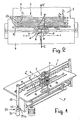
- FIGS. 1 and 2 show a laying device known from EP 0 778 236 A and EP 0 062 753 B, which serves to fold a flexible, in particular also an elastically stretchable, belt 2 in zigzag-shaped loops 2a which are arranged one behind the other like a packet, ie one Band loop position 3 to form.
- the folded band 2 or its loops 2a then has rectilinear, mutually adjacent sections and lateral 180 ° -Kehren, that is folds 2b.
- the zigzag loops 2a are shown slightly pulled apart for reasons of clarity; in practice but close to each other.
- This so folded band which is preferably a textile tape, is then further processed in the textile industry; it allows easy removal in the direction of any processing machines.
- so folded tapes can be stored much more compact and sent, as would be possible, for example, in coils.
- the laying device 1 is shown in detail in Figure 1, but in the following only the essential components for the present invention are explained. With regard to the other design features not explained here, reference is made in full to the documents EP 0778236A and EP 0062753B already mentioned at this point.
- the device 1 has a support plate 4 for the belt 2 to be folded or for the folded zigzag belt loops 2a.
- a laying carriage 6 is arranged movable back and forth perpendicular to the tape feed direction X, see the arrows Y in Figure 2.
- the laying carriage 6 has two laying rollers 7 and 8, which are rotatably mounted side by side about two parallel axes. The axes of rotation of the laying rollers 7.8 are perpendicular to the direction of displacement Y of the laying carriage 6 and perpendicular to the tape feed direction X.
- a vertical guide gap for the tape to be laid 2 is formed; in this guide gap runs between two guide rods 10 of a guide device 11 guided belt 2 in the feed direction X a.
- the band 2 is in vertical, that is upright position.
- the gap between the laying rollers 7,8 is dimensioned such that a friction entrainment of the belt 2 takes place through the peripheral surface of each of the two laying rollers 7,8.
- the laying rollers 7, 8 are each driven in the same direction, the direction of rotation in each case being dependent on the displacement direction of the laying carriage 6.
- FIG. 2 This dependency is illustrated in FIG. 2, according to which when the laying carriage 6 is displaced to the left (continuous arrow Y), the laying rollers 7, 8 rotate to the right (solid arrow W). When moving to the right (dashed arrow Y) the laying rollers 7,8 turn to the left (dashed arrow W).
- the strip material 2 is thereby taken respectively by the rear laying roller 7 or 8 in the direction of displacement by conditioning and pulled and transported on.
- the described drive banding is achieved in regular zigzag belt loops 2a.
- the change in the direction of rotation W of laying rollers 7.8 is carried out in each case at the reversal point of the sliding movement of the laying carriage 6.
- the laid belt loops are further pushed packet-like, that is, in a feed direction X corresponding discharge direction X 'moved on.
- braking means which act on the longitudinal edges of the band 2 with a pressure force in the folding area.
- An essential part of this braking means is a pressure bar 12, which is arranged in the region of the laying rollers 7.8 at the band exit side and whose length is at least equal to the range of movement of the laying carriage 6.
- the pressure bar 12 in this case runs parallel to the direction of displacement of the laying carriage 6 and preferably above this, so that the pressure strip acts on the upper longitudinal edge of the belt 2 by pushing the belt 2 slightly from top to bottom with its belt-facing, lower pressure surface 14.
- the pressure bar 12 cooperates with a lower, arranged in the region of the support plate 4 brake bar 16 by the band or its last loop 2 a between the brake bar 16 and the pressure bar 12 is practically clamped.
- the folds 2b are usually in a row behind each other.
- the pleats 2b are not all aligned in a row, but every other pleat 2c opposite the first pleat 2b is set back, as indicated in dashed line in Figure 2 is indicated. Even a multiple displacement of the wrinkles is thus possible.
- the pressure bar 12 is attached to both ends of vertical St onlyem 18, which are movable by means of piston / cylinder units 20 and spindles 22 up and down.
- the piston / cylinder units 20 are used for periodically lifting the pressure bar 12 when transferring a belt loop layer 3 of the laying device 1 in aphobiaemahmevorraum 24, as is apparent from Figure 3.
- An adjusting device 25 is used to adjust the size of the contact pressure of the pressure bar 12 on the belt loops.
- the adjusting device 25 has a stepper motor 25a, which cooperates via a gear 25b, for example, a chain or toothed belt transmission with the spindle 22 which is connected via a thread with the uprights 18, so that the distance of the stator 18 to the piston / cylinder Aggregates 20 and thereby the pressure of the pressure bar 12 on the belt loop is changeable.
- a gear 25b for example, a chain or toothed belt transmission with the spindle 22 which is connected via a thread with the uprights 18, so that the distance of the stator 18 to the piston / cylinder Aggregates 20 and thereby the pressure of the pressure bar 12 on the belt loop is changeable.
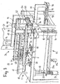
- Figures 3 to 6 describe a system for packaging tape loop layers, which are produced in the laying device 1 and are transferred to the transfer device 24 for packaging.
- the transfer device 26 has on the feed side of the belt 2 to the laying device 1 finger-like push members 28 which can be lowered from a raised rest position into a working position shown in Figure 3, in which they are parallel to the support plate of the belt loop position.
- the finger-like push members 28 are attached to a boom 30, which are movable by means of a carriage 32 on a vertical guide 34 from the illustrated working position into a vertically raised rest position in which it does not hinder the feeding of the belt 2 in the laying device 1.
- a piston / cylinder unit 36 whose piston rod 38 is connected to the arm serves for vertical displacement.
- a piston / cylinder unit 40 is used to move the push members 28 under the pressure bar 12, for which purpose on the vertical guide 34, a carriage 39 is arranged, which is displaceable along a rail 41.
- the belt loop days 3 is advanced in the direction of the transfer device 24.
- the transfer device 26 has vertically aligned driver fingers 42, which consist of the one shown in FIG Rest position against the support plate 4 are lowered and there between the push members 28 are retractable to the tape loop position transversely transversely to the loop position in the transfer device 24 to move.
- the entrainment fingers 42 are fastened analogously to the abutment members 28 on a cantilever 44, which can be moved by means of a carriage 46 on a vertical guide 48.
- a piston / cylinder unit 50 is connected by means of a clamp rod 52 with the boom 44 and serves for the vertical movement of the driver fingers 42 from the rest position to the working position.
- a piston / cylinder unit 54 is used to move the carriage 55 having a vertical guide 48 along the horizontal rail 41st
- braking strips 56 are arranged in the displacement of the folds of the belt loop position.
- Such braking strips can be formed for example by roughening the support plate 4 or by sticking rough strips.
- resiliently receding stop members 62 are arranged in the region between the folds of the belt loop position to align itself in takeover direction bulging tape parts parallel to the loop position ,
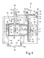
- the transfer device 24 is designed as a stacking device for the belt loop layers.
- the stacking device has a serving as a stop for the tape loop position to be adopted rear wall 64, further by the thickness of the belt loop layer gradually lowerable bottom 66 and a respect to the bottom and the thickness of the belt loop position and thus the width of the belt adjustable cover 68, which at least as Upper guide for a transferable belt loop position is used.
- the cover 68 is attached to a boom 70 via guide rods 72 height adjustable.
- a drive 74 for example, a piston / cylinder unit 74 serves on the one hand for advancing the lid 68 as the upper guide the tape loop position in the transfer of the laying device and on the other hand for lowering the lid 68 in synchronism with the bottom 66 during lowering of the stacking device.
- the bottom 66 is attached to the rear wall 64 and lowerable with this.
- the rear wall 64 is connected via a threaded part 76 with a spindle 78 which is driven by a geared motor 80.
- the bottom 66 can be lowered in each case by the thickness of a belt loop layer so that a plurality of belt loop layers can be stacked one above the other.
- a receiving base 82 which can be extended over the stacking device in the transfer device is provided, which is formed from two counter-retractable base parts 84, which can each be laterally extended from the stacking region by means of a drive 86, for example a piston / cylinder unit. to settle a recorded tape loop position on the stack.
- the stacking device 24 can be lowered into a packing station, in which the belt loop layer stack can be ejected from the stacking device into a laterally assigned packaging container 90 by means of an ejection punch 88.
- the ejection punch 88 is attached to an arm 92 which is movable by means of a carriage 94 along a rail 96.
- a piston / cylinder unit 98 serves to displace the punch.
- the packaging container 90 is arranged on a carrier 100, which can be delivered by means of a carriage 102 along the rail 96 against the stacking device. To drive a piston / cylinder unit 104 is used.
- the carrier 100 includes stops 106 for aligning the packaging container 90 with respect to the stacking device 24th
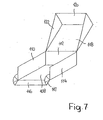
- FIG. 7 shows a preferred packaging container 90 for receiving a stack of tape loop layers.
- the packaging container 90 which is preferably made of cardboard, contains a bottom 108 with three molded sidewalls 110,112,114.
- a hinged side wall portion 116 is arranged with lateral folding elements 117.
- a lid 118 is hinged, which has a fourth side 116 at least largely covering edge portion 120 which is supported by extending side portions 122 of the lid 118.
- a non-illustrated memory programmable controller with microprocessors used for coordinated control of the movements and settings of the various components of the system to achieve at least semi-automatic, but preferably fully automatic workflows.
- the control device it is possible on the control device to set the desired length of the belt loops 2a during the folding process, as indicated in FIG.
- an optimal packaging but also a uniform over the entire pack density of the belt loops, whereby over the entire pack uniform quality of the packed band is achieved.
- the achievable improvements are achieved with simultaneous increase in performance and reduced personnel deployment.
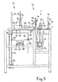
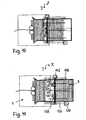
- Figures 8 to 11 show a further simplified embodiment of a system for packaging a laid in zigzag loops flexible tape 2 in a schematic representation.
- the schematically illustrated laying device 1 corresponds to that of FIGS. 1 to 6.
- the laying device 1 downstream of the transfer device 26a has a laying area cross-beam 124, which is arranged on both sides of the laying area of linear guides 126 by means of a drive 128, for example, connected to a linear gear stepper motor, movable in the X direction.
- the displacement beam carries two engravers 130,132, each of which by means of a drive 134 against the belt loop position 3 on and extendable and by means of slide 136,138 along the sliding beam 124 are movable.
- drives 134 for the engraver for example, serve piston / cylinder units 140, the piston rods are designed as engravers 130,132.
- the carriages 136, 138 can be moved in opposite directions in the Y-direction by means of a further drive 142, for example a circulating pulling element from a central middle position over the laying area or the belt loop position, thus transversely to the displacement direction of the displacement bar 124.
- a further drive 142 for example a circulating pulling element from a central middle position over the laying area or the belt loop position, thus transversely to the displacement direction of the displacement bar 124.
- This system according to FIGS. 8 to 11 does not require any abutment members for piercing a band loop position under the pressure strip, but works as follows.
- a piercing device 130 is first retracted at a predetermined location between a belt loop 2a and the shift bar 124 as far advanced in the X direction until the belt loop is opened. Then, the first engraver 130 is raised again and both engravers 130,132 retracted in a central position in the opened belt loop 2a and against each other in the Y direction apart drove until they have a distance from the edge of the tape loop layer, which corresponds to about a quarter of the width of the tape loop position, such as this is shown in Figure 10, whereby the separation of the belt loop is completed.
- the shift bar 124 is lowered at Stechem 130,132 in the X direction until the separated tape loop position has reached the stacking device 144 of the transfer device. Then the engraver 130,132 are raised and moved back the shift bar in the starting position for transferring another tape loop position.
- the separation and transfer of the tape loop position can be done in interrupted before preferably, however, continuous loop laying the laying device.
Landscapes
- Engineering & Computer Science (AREA)
- Mechanical Engineering (AREA)
- Auxiliary Devices For And Details Of Packaging Control (AREA)
- Folding Of Thin Sheet-Like Materials, Special Discharging Devices, And Others (AREA)
- Container Filling Or Packaging Operations (AREA)
- Basic Packing Technique (AREA)
- Yarns And Mechanical Finishing Of Yarns Or Ropes (AREA)
- Nonwoven Fabrics (AREA)
- Cartons (AREA)
- Wrappers (AREA)
Claims (18)
- Installation servant à emballer une bande souple déposée sous forme de couches de boucles en zigzag, en particulier d'une bande textile, comprenant un dispositif de positionnement (1) disposé sur une plaque d'appui (4) à plat, dispositif qui contient un chariot de positionnement (6) pouvant se déplacer selon un mouvement de va-et-vient et présentant deux rouleaux de positionnement (7, 8) entraînés en rotation dans le même sens et disposés l'un à côté de l'autre, leurs axes étant parallèles, une bande unique (2) pouvant être prise entre ces rouleaux par un côté d'alimentation (10) et pliée par le mouvement de va-et-vient du chariot de positionnement (6) perpendiculaire au sens d'entrée (X) de la bande, sachant qu'elle peut être re-déplacée sous la barre de compression (12) dans un sens d'éloignement (X') correspondant au sens d'alimentation (X),
caractérisée en ce que
le dispositif de positionnement (1) est associé à un dispositif de transfert (26, 26a) pour former une couche de boucles de la bande (3) de grandeur prédéterminée et pour transférer directement ou indirectement la couche de boucles de la bande (3) dans un récipient d'emballage (90), une mémoire d'un dispositif de commande programmable étant prévue pour les composants de l'installation. - Installation selon la revendication 1,
caractérisée en ce que
le dispositif de commande est réalisé pour commander l'installation de manière entièrement automatique. - Installation selon la revendication 1 ou 2,
caractérisée en ce que
la longueur des boucles de la bande peut être réglée, d'une boucle à l'autre, sur le dispositif de commande selon une grandeur alternante. - Installation selon l'une des revendications 1 à 3,
caractérisée en ce que
la longueur de la bande est réglable sur le dispositif de commande pour chaque couche de boucles de la bande, et dans le cas d'un paquet de plusieurs couches, la longueur totale de la bande du paquet est de préférence régulièrement répartie sur toutes les couches. - Installation selon l'une des revendications 1 à 4,
caractérisée en ce que
le dispositif de positionnement (1) présente, dans la zone de positionnement, une barre de compression (12) passant sur toute la longueur des boucles et peut être avancée perpendiculairement à une plaque d'appui (4) pour la couche de boucles de la bande (3) et pressée contre les bords des boucles de la bande (2a) selon une grandeur réglable, et elle est de préférence munie d'un entraînement de levage commandable (20, 22) pendant le transfert. - Installation selon l'une des revendications 1 à 5,
caractérisée en ce que
le dispositif de transfert (26a) présente des piqueurs (130, 132) disposés derrière le dispositif de positionnement (1) et placés sur une poutre de déplacement (124), sachant qu'ils peuvent être descendus par le dessus entre deux boucles d'une bande (2a) et qu'ils sont disposés latéralement pour se déplacer les uns par rapport aux autres, afin de séparer deux boucles de la bande et de transférer la couche de boucles de la bande (3) précédente. - Installation selon l'une des revendications 1 à 5,
caractérisée en ce que
le dispositif de transfert (26) présente sur le dispositif de positionnement (1), de préférence des organes de poussée en forme de doigts (28) du côté de l'alimentation de la bande (2) qui peuvent être déplacés d'une position de repos, n'agissant pas sur la course de la bande, dans une position de travail, dans laquelle ils sont déplacés sous la barre de compression (12) parallèlement à la plaque d'appui (4) de la couche de boucles de la bande (3) jusqu'à ce que des organes entraînement (42) puissent être descendus entre, ou derrière, la couche de boucles de la bande, de l'autre côté de la barre de compression (12) à partir d'une position de repos, dans le but de déplacer dans un dispositif de reprise (24) la couche de boucles de la bande (3) transversalement à la couche de boucles au moyen des organes entraînement - Installation selon la revendication 7,
caractérisée en ce que
les organes de poussée (28) peuvent être abaissés verticalement dans la position de travail à partir d'une position de repos relevée sur la plaque d'appui (4). - Installation selon la revendication 7,
caractérisée en ce que
les organes entraînement (42) sont réalisés en forme de doigts et peuvent être descendus perpendiculairement vers le bas entre les organes de poussée (28) à partir d'une position de repos supérieure. - Installation selon l'une des revendications 1 à 9,
caractérisée en ce que
la plaque d'appui (4) présente des bandes de frein (56) depuis le dispositif de positionnement (1) jusque dans le dispositif de reprise (24) le long de la trajectoire de déplacement des plis (2b, 2c) des boucles de la bande (2a). - Installation selon l'une des revendications 1 à 10,
caractérisée en ce que
sur la plaque d'appui (4), sont disposées des barres de guidage (60) dirigées transversalement à la couche de boucles pour guider les couches de boucles de la bande (3). - Installation selon l'une des revendications 1 à 11,
caractérisée en ce que,
dans le dispositif de reprise (24), au moins un élément de butée (62) reculant sous l'action d'un ressort (62) est disposé dans la zone comprise entre les plis (2b, 2c), pour que les parties de bande recourbées dans le dispositif de reprise se dirigent parallèlement à la couche de boucles (3). - Installation selon l'une des revendications 1 à 12,
caractérisée en ce que
le dispositif de reprise (24) est un dispositif d'empilement pour les couches de boucles de la bande (3). - Installation selon la revendication 13,
caractérisée en ce que
le dispositif d'empilement (24) présente une paroi arrière (64) servant de butée pour les couches de boucles de la bande (3) à reprendre, un fond (66) pouvant être abaissé autour de l'épaisseur des couches de boucles de la bande (3) et un couvercle (68) réglable par rapport au fond (66) sert au moins de guidage supérieur pour une couche de boucles de la bande (3) à transférer. - Installation selon la revendication 14,
caractérisée en ce que
le couvercle (68) servant de délimitation supérieure de l'empilement peut être déplacé parallèlement avec le fond (66). - Installation selon l'une des revendications 1 à 15,
caractérisée en ce qu'
elle présente, dans le dispositif de reprise (24), un fond de réception (82) pouvant se retirer dans le plan de fond et qui comprend de préférence deux moitiés de fond (84) pouvant être enlevées latéralement de manière opposée. - Installation selon l'une des revendications 13 à 16,
caractérisée en ce que
le dispositif d'empilement (24) peut être abaissé dans un poste d'emballage, dans lequel la pile de boucles de la bande peut être expulsée du dispositif d'empilement (24) par un piston d'expulsion (88) jusque dans un récipient d'emballage (90) associé. - Installation selon l'une des revendications 1 à 17 en combinaison avec un récipient d'emballage,
caractérisée en ce que
le récipient d'emballage (90) présente un fond (108) avec trois parois latérales moulées (110, 112, 114), la quatrième face servant à l'introduction du paquet de boucles de la bande présentant un élément de paroi latéral (116) rabattable vers le bas et un couvercle (118) dont une partie du bord (120) recouvre la quatrième face au moins sur sa plus grande partie, ce couvercle étant articulé sur la paroi latérale opposée.
Applications Claiming Priority (3)
| Application Number | Priority Date | Filing Date | Title |
|---|---|---|---|
| CH110902 | 2002-06-27 | ||
| CH11092002 | 2002-06-27 | ||
| PCT/CH2003/000387 WO2004002833A1 (fr) | 2002-06-27 | 2003-06-16 | Installation servant a emballer une bande souple disposee en couches de boucles en zigzag, en particulier d'une bande textile |
Publications (2)
| Publication Number | Publication Date |
|---|---|
| EP1515894A1 EP1515894A1 (fr) | 2005-03-23 |
| EP1515894B1 true EP1515894B1 (fr) | 2006-03-01 |
Family
ID=29783975
Family Applications (1)
| Application Number | Title | Priority Date | Filing Date |
|---|---|---|---|
| EP03727120A Expired - Lifetime EP1515894B1 (fr) | 2002-06-27 | 2003-06-16 | Installation servant a emballer une bande souple disposee en couches de boucles en zigzag, en particulier d'une bande textile |
Country Status (10)
| Country | Link |
|---|---|
| US (1) | US7127871B2 (fr) |
| EP (1) | EP1515894B1 (fr) |
| JP (1) | JP2005535519A (fr) |
| CN (1) | CN100364861C (fr) |
| AT (1) | ATE318760T1 (fr) |
| AU (1) | AU2003233903A1 (fr) |
| BR (1) | BR0312207B1 (fr) |
| DE (1) | DE50302528D1 (fr) |
| ES (1) | ES2257669T3 (fr) |
| WO (1) | WO2004002833A1 (fr) |
Cited By (1)
| Publication number | Priority date | Publication date | Assignee | Title |
|---|---|---|---|---|
| CN102030221A (zh) * | 2010-11-19 | 2011-04-27 | 天津赛象科技股份有限公司 | 摆片叠片称量及升降装置以及其控制方法 |
Families Citing this family (6)
| Publication number | Priority date | Publication date | Assignee | Title |
|---|---|---|---|---|
| US20110206897A1 (en) * | 2010-02-19 | 2011-08-25 | Knapp Kenneth D | Lapped rolls of insulation and process for manufacturing same |
| CN104071400B (zh) * | 2014-07-22 | 2016-02-24 | 广东海洋大学 | 网衣打包机 |
| CN104608971B (zh) * | 2015-01-27 | 2019-06-14 | 东阳市沃特塑胶有限公司 | 一种波纹管自动包装机 |
| US10895708B2 (en) * | 2015-08-05 | 2021-01-19 | Electric Motion Company, Inc. | Locatable duct tracer wire bonding connector |
| CN111847048A (zh) * | 2020-07-07 | 2020-10-30 | 林菊香 | 一种用于纺织的自动码布机 |
| CN116395224B (zh) * | 2023-05-31 | 2023-09-05 | 南昌汇恒自动化技术有限公司 | 一种输液器拉管与缠绕机构 |
Family Cites Families (13)
| Publication number | Priority date | Publication date | Assignee | Title |
|---|---|---|---|---|
| US3707063A (en) * | 1971-03-17 | 1972-12-26 | Christie Mfg Co | Apparatus for packaging ribbon-like material |
| US3942300A (en) * | 1974-04-08 | 1976-03-09 | Dufaylite Developments Limited | Apparatus for lapping a continuous length of honeycomb material |
| US3868809A (en) * | 1974-04-15 | 1975-03-04 | Woodrow W Bledsoe | Fiber baling apparatus |
| DE3114395C2 (de) * | 1981-04-09 | 1983-04-28 | Hans 5600 Wuppertal Affüpper | Vorrichtung zum zickzackförmigen Falten in Schlaufen eines kontinuierlich zugeführten, flexiblen Bandes |
| JPS5926861A (ja) * | 1982-07-31 | 1984-02-13 | Orion Kikai Kogyo Kk | テイシユ−製品の分別搬送装置 |
| DE3334111A1 (de) * | 1983-09-21 | 1985-03-28 | Ernst Roederstein Spezialfabrik für Kondensatoren GmbH, 8300 Landshut | Vorrichtung zur harmonikaartigen verpackung gegurteter bauelemente |
| US4573958A (en) * | 1984-05-08 | 1986-03-04 | Biesinger Peter J | Cuttling machine for continuous input of web |
| GB8427394D0 (en) * | 1984-10-30 | 1984-12-05 | Jeffrey P | Forming and packaging articles |
| DE3444897A1 (de) * | 1984-12-08 | 1986-06-12 | Bayer Ag, 5090 Leverkusen | Mineralwollegebinde und verfahren zu dessen herstellung |
| DE29519515U1 (de) * | 1995-12-09 | 1996-01-25 | Hans Affuepper Textilmaschinen | Vorrichtung zum Falten eines Bandmaterials in Zickzack-Schlaufen |
| US6321512B1 (en) * | 1999-03-08 | 2001-11-27 | Bki Holding Corporation | Method of packaging a strip of material |
| US6305146B1 (en) * | 1999-03-09 | 2001-10-23 | Jensen Ag Burgdorf | Process for the final folding and subsequent storage of a piece of linen and final folding means |
| CN2483365Y (zh) * | 2001-05-21 | 2002-03-27 | 马镇鑫 | 一种塑料膜的折叠式收取装置 |
-
2003
- 2003-06-16 AT AT03727120T patent/ATE318760T1/de not_active IP Right Cessation
- 2003-06-16 ES ES03727120T patent/ES2257669T3/es not_active Expired - Lifetime
- 2003-06-16 CN CNB038150964A patent/CN100364861C/zh not_active Expired - Fee Related
- 2003-06-16 AU AU2003233903A patent/AU2003233903A1/en not_active Abandoned
- 2003-06-16 WO PCT/CH2003/000387 patent/WO2004002833A1/fr active IP Right Grant
- 2003-06-16 US US10/521,303 patent/US7127871B2/en not_active Expired - Fee Related
- 2003-06-16 EP EP03727120A patent/EP1515894B1/fr not_active Expired - Lifetime
- 2003-06-16 BR BRPI0312207-7A patent/BR0312207B1/pt not_active IP Right Cessation
- 2003-06-16 JP JP2004516400A patent/JP2005535519A/ja active Pending
- 2003-06-16 DE DE50302528T patent/DE50302528D1/de not_active Expired - Fee Related
Cited By (1)
| Publication number | Priority date | Publication date | Assignee | Title |
|---|---|---|---|---|
| CN102030221A (zh) * | 2010-11-19 | 2011-04-27 | 天津赛象科技股份有限公司 | 摆片叠片称量及升降装置以及其控制方法 |
Also Published As
| Publication number | Publication date |
|---|---|
| CN100364861C (zh) | 2008-01-30 |
| BR0312207B1 (pt) | 2012-07-24 |
| EP1515894A1 (fr) | 2005-03-23 |
| BR0312207A (pt) | 2005-04-12 |
| AU2003233903A1 (en) | 2004-01-19 |
| CN1665717A (zh) | 2005-09-07 |
| WO2004002833A1 (fr) | 2004-01-08 |
| US7127871B2 (en) | 2006-10-31 |
| US20050235601A1 (en) | 2005-10-27 |
| ES2257669T3 (es) | 2006-08-01 |
| DE50302528D1 (de) | 2006-04-27 |
| ATE318760T1 (de) | 2006-03-15 |
| JP2005535519A (ja) | 2005-11-24 |
Similar Documents
| Publication | Publication Date | Title |
|---|---|---|
| DE3119657C2 (de) | Verfahren und Maschine zur Herstellung von Verpackungseinheiten | |
| EP0189090B1 (fr) | Dispositif de pliage de bandes | |
| DE19860018A1 (de) | Verpackungsautomat zur Konfektionierung von Produkten | |
| DE2827540B1 (de) | Stapelvorrichtung fuer Faltschachteln | |
| DE3836214C2 (fr) | ||
| DE2713135C2 (de) | Vorrichtung zum selbsttätigen Verladen von Säcken | |
| EP0413927B1 (fr) | Installation pour fabriquer des emballages pour des produits liquides | |
| EP0243799B1 (fr) | Dispositif de pliage de bandes | |
| EP0278120B1 (fr) | Plieuse en accordéon | |
| CH647735A5 (de) | Verfahren zur herstellung von stapeln aus gefalzten druckbogen und vorrichtung zur durchfuehrung des verfahrens. | |
| DE3421915A1 (de) | Verfahren und vorrichtung zum aufbauen und handhaben von stapeln aus bahnmaterial | |
| CH680363A5 (fr) | ||
| EP1515894B1 (fr) | Installation servant a emballer une bande souple disposee en couches de boucles en zigzag, en particulier d'une bande textile | |
| DE19533086A1 (de) | Verfahren und Vorrichtung zum Stapeln von flächigen Erzeugnissen, insbesondere Druckereiprodukten | |
| DE19541792A1 (de) | Einrichtung zur Hilfsstapelbildung beim Nonstopstapelwechsel im Ausleger einer Druckmaschine | |
| DE4401818C2 (de) | Klemmeinrichtung, insbesondere zum Einklemmen eines Bogenpakets beim Stapelwechsel in Stapelvorrichtungen für Papier- oder Kartonbögen | |
| EP0872443B1 (fr) | Dispositif pour former une pile partielle s'étandant perpendiculèrement aux feuilles imprimées rangées sur la tranche et une à côté de l'autre | |
| DE2729964A1 (de) | Verfahren und vorrichtung zum automatischen einschlagen einer mit ware gefuellten schale in eine plastikfolie | |
| EP2202158A1 (fr) | Dispositif de cerclage et son procédé de fonctionnement | |
| EP2112069B1 (fr) | Procédé et dispositif d'emballage de produits emballés par portions dans un dispositif d'emballage | |
| EP0563649B1 (fr) | Procédé et appareil pour former un enveloppement fermé autour d'un article | |
| EP0741101A2 (fr) | Méthode pour séparer une pile de cahiers dans un empileur et empileur pour la mise en oeuvre de cette méthode | |
| EP1050463B1 (fr) | Machine de liage pour lier une pile d'objets | |
| DE2547114A1 (de) | Verfahren und vorrichtung zum ueberfuehren von staeben von einer streckbank zu einem foerderer | |
| DE4202254A1 (de) | Verfahren zur zufuehrung von bahnen aus papier, tissue, nonwoven oder dergleichen zu einer falzmaschine zur herstellung ein oder mehrmals in querrichtung gefalteter bahnabschnitte und zur abgabe der bahnabschnitte in aus abgezaehlten einzelstuecken bestehenden paeckchen sowie vorrichtung zur durchfuehrung des verfahrens |
Legal Events
| Date | Code | Title | Description |
|---|---|---|---|
| PUAI | Public reference made under article 153(3) epc to a published international application that has entered the european phase |
Free format text: ORIGINAL CODE: 0009012 |
|
| 17P | Request for examination filed |
Effective date: 20041129 |
|
| AK | Designated contracting states |
Kind code of ref document: A1 Designated state(s): AT BE BG CH CY CZ DE DK EE ES FI FR GB GR HU IE IT LI LU MC NL PT RO SE SI SK TR |
|
| AX | Request for extension of the european patent |
Extension state: AL LT LV MK |
|
| RAP1 | Party data changed (applicant data changed or rights of an application transferred) |
Owner name: TEXTILMA AG |
|
| GRAP | Despatch of communication of intention to grant a patent |
Free format text: ORIGINAL CODE: EPIDOSNIGR1 |
|
| DAX | Request for extension of the european patent (deleted) | ||
| GRAS | Grant fee paid |
Free format text: ORIGINAL CODE: EPIDOSNIGR3 |
|
| GRAA | (expected) grant |
Free format text: ORIGINAL CODE: 0009210 |
|
| AK | Designated contracting states |
Kind code of ref document: B1 Designated state(s): AT BE BG CH CY CZ DE DK EE ES FI FR GB GR HU IE IT LI LU MC NL PT RO SE SI SK TR |
|
| PG25 | Lapsed in a contracting state [announced via postgrant information from national office to epo] |
Ref country code: RO Free format text: LAPSE BECAUSE OF FAILURE TO SUBMIT A TRANSLATION OF THE DESCRIPTION OR TO PAY THE FEE WITHIN THE PRESCRIBED TIME-LIMIT Effective date: 20060301 Ref country code: SI Free format text: LAPSE BECAUSE OF FAILURE TO SUBMIT A TRANSLATION OF THE DESCRIPTION OR TO PAY THE FEE WITHIN THE PRESCRIBED TIME-LIMIT Effective date: 20060301 Ref country code: IE Free format text: LAPSE BECAUSE OF FAILURE TO SUBMIT A TRANSLATION OF THE DESCRIPTION OR TO PAY THE FEE WITHIN THE PRESCRIBED TIME-LIMIT Effective date: 20060301 Ref country code: FI Free format text: LAPSE BECAUSE OF FAILURE TO SUBMIT A TRANSLATION OF THE DESCRIPTION OR TO PAY THE FEE WITHIN THE PRESCRIBED TIME-LIMIT Effective date: 20060301 Ref country code: NL Free format text: LAPSE BECAUSE OF FAILURE TO SUBMIT A TRANSLATION OF THE DESCRIPTION OR TO PAY THE FEE WITHIN THE PRESCRIBED TIME-LIMIT Effective date: 20060301 Ref country code: SK Free format text: LAPSE BECAUSE OF FAILURE TO SUBMIT A TRANSLATION OF THE DESCRIPTION OR TO PAY THE FEE WITHIN THE PRESCRIBED TIME-LIMIT Effective date: 20060301 |
|
| REG | Reference to a national code |
Ref country code: GB Ref legal event code: FG4D Free format text: NOT ENGLISH |
|
| REG | Reference to a national code |
Ref country code: CH Ref legal event code: EP Ref country code: CH Ref legal event code: NV Representative=s name: SCHMAUDER & PARTNER AG PATENTANWALTSBUERO |
|
| GBT | Gb: translation of ep patent filed (gb section 77(6)(a)/1977) |
Effective date: 20060301 |
|
| REG | Reference to a national code |
Ref country code: IE Ref legal event code: FG4D Free format text: LANGUAGE OF EP DOCUMENT: GERMAN |
|
| REF | Corresponds to: |
Ref document number: 50302528 Country of ref document: DE Date of ref document: 20060427 Kind code of ref document: P |
|
| PG25 | Lapsed in a contracting state [announced via postgrant information from national office to epo] |
Ref country code: SE Free format text: LAPSE BECAUSE OF FAILURE TO SUBMIT A TRANSLATION OF THE DESCRIPTION OR TO PAY THE FEE WITHIN THE PRESCRIBED TIME-LIMIT Effective date: 20060601 Ref country code: BG Free format text: LAPSE BECAUSE OF FAILURE TO SUBMIT A TRANSLATION OF THE DESCRIPTION OR TO PAY THE FEE WITHIN THE PRESCRIBED TIME-LIMIT Effective date: 20060601 Ref country code: DK Free format text: LAPSE BECAUSE OF FAILURE TO SUBMIT A TRANSLATION OF THE DESCRIPTION OR TO PAY THE FEE WITHIN THE PRESCRIBED TIME-LIMIT Effective date: 20060601 |
|
| PG25 | Lapsed in a contracting state [announced via postgrant information from national office to epo] |
Ref country code: BE Free format text: LAPSE BECAUSE OF NON-PAYMENT OF DUE FEES Effective date: 20060630 Ref country code: MC Free format text: LAPSE BECAUSE OF NON-PAYMENT OF DUE FEES Effective date: 20060630 |
|
| PG25 | Lapsed in a contracting state [announced via postgrant information from national office to epo] |
Ref country code: PT Free format text: LAPSE BECAUSE OF FAILURE TO SUBMIT A TRANSLATION OF THE DESCRIPTION OR TO PAY THE FEE WITHIN THE PRESCRIBED TIME-LIMIT Effective date: 20060801 |
|
| REG | Reference to a national code |
Ref country code: ES Ref legal event code: FG2A Ref document number: 2257669 Country of ref document: ES Kind code of ref document: T3 |
|
| NLV1 | Nl: lapsed or annulled due to failure to fulfill the requirements of art. 29p and 29m of the patents act | ||
| REG | Reference to a national code |
Ref country code: IE Ref legal event code: FD4D |
|
| ET | Fr: translation filed | ||
| PLBE | No opposition filed within time limit |
Free format text: ORIGINAL CODE: 0009261 |
|
| STAA | Information on the status of an ep patent application or granted ep patent |
Free format text: STATUS: NO OPPOSITION FILED WITHIN TIME LIMIT |
|
| 26N | No opposition filed |
Effective date: 20061204 |
|
| PG25 | Lapsed in a contracting state [announced via postgrant information from national office to epo] |
Ref country code: AT Free format text: LAPSE BECAUSE OF NON-PAYMENT OF DUE FEES Effective date: 20060616 |
|
| BERE | Be: lapsed |
Owner name: TEXTILMA A.G. Effective date: 20060630 |
|
| PG25 | Lapsed in a contracting state [announced via postgrant information from national office to epo] |
Ref country code: CZ Free format text: LAPSE BECAUSE OF FAILURE TO SUBMIT A TRANSLATION OF THE DESCRIPTION OR TO PAY THE FEE WITHIN THE PRESCRIBED TIME-LIMIT Effective date: 20060301 Ref country code: GR Free format text: LAPSE BECAUSE OF FAILURE TO SUBMIT A TRANSLATION OF THE DESCRIPTION OR TO PAY THE FEE WITHIN THE PRESCRIBED TIME-LIMIT Effective date: 20060602 |
|
| PG25 | Lapsed in a contracting state [announced via postgrant information from national office to epo] |
Ref country code: EE Free format text: LAPSE BECAUSE OF FAILURE TO SUBMIT A TRANSLATION OF THE DESCRIPTION OR TO PAY THE FEE WITHIN THE PRESCRIBED TIME-LIMIT Effective date: 20060301 |
|
| PG25 | Lapsed in a contracting state [announced via postgrant information from national office to epo] |
Ref country code: HU Free format text: LAPSE BECAUSE OF FAILURE TO SUBMIT A TRANSLATION OF THE DESCRIPTION OR TO PAY THE FEE WITHIN THE PRESCRIBED TIME-LIMIT Effective date: 20060902 Ref country code: LU Free format text: LAPSE BECAUSE OF NON-PAYMENT OF DUE FEES Effective date: 20060616 |
|
| PGFP | Annual fee paid to national office [announced via postgrant information from national office to epo] |
Ref country code: ES Payment date: 20080627 Year of fee payment: 6 |
|
| PG25 | Lapsed in a contracting state [announced via postgrant information from national office to epo] |
Ref country code: CY Free format text: LAPSE BECAUSE OF FAILURE TO SUBMIT A TRANSLATION OF THE DESCRIPTION OR TO PAY THE FEE WITHIN THE PRESCRIBED TIME-LIMIT Effective date: 20060301 |
|
| PGFP | Annual fee paid to national office [announced via postgrant information from national office to epo] |
Ref country code: FR Payment date: 20080613 Year of fee payment: 6 |
|
| PGFP | Annual fee paid to national office [announced via postgrant information from national office to epo] |
Ref country code: GB Payment date: 20080620 Year of fee payment: 6 |
|
| REG | Reference to a national code |
Ref country code: CH Ref legal event code: PCAR Free format text: SCHMAUDER & PARTNER AG PATENT- UND MARKENANWAELTE VSP;ZWAENGIWEG 7;8038 ZUERICH (CH) |
|
| PGFP | Annual fee paid to national office [announced via postgrant information from national office to epo] |
Ref country code: IT Payment date: 20090620 Year of fee payment: 7 Ref country code: TR Payment date: 20090526 Year of fee payment: 7 |
|
| PGFP | Annual fee paid to national office [announced via postgrant information from national office to epo] |
Ref country code: CH Payment date: 20090617 Year of fee payment: 7 |
|
| PGFP | Annual fee paid to national office [announced via postgrant information from national office to epo] |
Ref country code: DE Payment date: 20090622 Year of fee payment: 7 |
|
| GBPC | Gb: european patent ceased through non-payment of renewal fee |
Effective date: 20090616 |
|
| REG | Reference to a national code |
Ref country code: FR Ref legal event code: ST Effective date: 20100226 |
|
| PG25 | Lapsed in a contracting state [announced via postgrant information from national office to epo] |
Ref country code: FR Free format text: LAPSE BECAUSE OF NON-PAYMENT OF DUE FEES Effective date: 20090630 |
|
| PG25 | Lapsed in a contracting state [announced via postgrant information from national office to epo] |
Ref country code: GB Free format text: LAPSE BECAUSE OF NON-PAYMENT OF DUE FEES Effective date: 20090616 |
|
| REG | Reference to a national code |
Ref country code: ES Ref legal event code: FD2A Effective date: 20090617 |
|
| PG25 | Lapsed in a contracting state [announced via postgrant information from national office to epo] |
Ref country code: ES Free format text: LAPSE BECAUSE OF NON-PAYMENT OF DUE FEES Effective date: 20090617 |
|
| REG | Reference to a national code |
Ref country code: CH Ref legal event code: PL |
|
| PG25 | Lapsed in a contracting state [announced via postgrant information from national office to epo] |
Ref country code: IT Free format text: LAPSE BECAUSE OF NON-PAYMENT OF DUE FEES Effective date: 20100616 |
|
| PG25 | Lapsed in a contracting state [announced via postgrant information from national office to epo] |
Ref country code: DE Free format text: LAPSE BECAUSE OF NON-PAYMENT OF DUE FEES Effective date: 20110101 Ref country code: CH Free format text: LAPSE BECAUSE OF NON-PAYMENT OF DUE FEES Effective date: 20100630 Ref country code: LI Free format text: LAPSE BECAUSE OF NON-PAYMENT OF DUE FEES Effective date: 20100630 |
|
| PG25 | Lapsed in a contracting state [announced via postgrant information from national office to epo] |
Ref country code: TR Free format text: LAPSE BECAUSE OF NON-PAYMENT OF DUE FEES Effective date: 20100616 |