EP1515878B1 - Straffvorrichtung mit einem abgedichteten gasgeneratorgehäuse - Google Patents
Straffvorrichtung mit einem abgedichteten gasgeneratorgehäuse Download PDFInfo
- Publication number
- EP1515878B1 EP1515878B1 EP03761460A EP03761460A EP1515878B1 EP 1515878 B1 EP1515878 B1 EP 1515878B1 EP 03761460 A EP03761460 A EP 03761460A EP 03761460 A EP03761460 A EP 03761460A EP 1515878 B1 EP1515878 B1 EP 1515878B1
- Authority
- EP
- European Patent Office
- Prior art keywords
- gas generator
- cable
- tensioning device
- generator housing
- seal body
- Prior art date
- Legal status (The legal status is an assumption and is not a legal conclusion. Google has not performed a legal analysis and makes no representation as to the accuracy of the status listed.)
- Expired - Lifetime
Links
- 238000007789 sealing Methods 0.000 claims description 40
- 239000013013 elastic material Substances 0.000 claims description 2
- 239000007789 gas Substances 0.000 description 60
- 125000006850 spacer group Chemical group 0.000 description 3
- 238000004873 anchoring Methods 0.000 description 1
- 230000015572 biosynthetic process Effects 0.000 description 1
- 238000011161 development Methods 0.000 description 1
- 230000018109 developmental process Effects 0.000 description 1
- 238000009434 installation Methods 0.000 description 1
Images
Classifications
-
- B—PERFORMING OPERATIONS; TRANSPORTING
- B60—VEHICLES IN GENERAL
- B60R—VEHICLES, VEHICLE FITTINGS, OR VEHICLE PARTS, NOT OTHERWISE PROVIDED FOR
- B60R22/00—Safety belts or body harnesses in vehicles
- B60R22/18—Anchoring devices
- B60R22/195—Anchoring devices with means to tension the belt in an emergency, e.g. means of the through-anchor or splitted reel type
- B60R22/1952—Transmission of tensioning power by cable; Return motion locking means therefor
Definitions
- the invention relates to a tensioning device for a safety belt with a tube for guiding a pressure gas piston and a connected to the piston and connected to a belt to be tightened Gurtgurtkomponente connected to the recording of the gas generator serving gas generator housing in the pipe and between the gas generator housing and a piston Pressure chamber is left, and wherein the cable is guided in a parallel arrangement to the gas generator through the gas generator housing and through the pressure chamber to the piston.
- a tensioning device with the aforementioned features is described in DE 199 18 596 A1; due to the parallel orientation of gas generator and rope and their common arrangement in the gas generator housing receiving them and inserted into the tube, the problem arises that the triggering of the gas generator in the pressure chamber Part of the gas flowing in the pipe can flow out along the passage of the cable laid in the gas generator housing. Since this passage channel to simplify the installation of the tensioning device in its diameter has a certain excess with respect to the rope diameter, the leakage losses of gas are correspondingly large. Since these gas losses are not available for the drive of the piston, the gas generator must be designed for the generation of a correspondingly large amount of gas.
- the invention is therefore based on the object to avoid the occurrence of gas leaks in a tensioning device with the generic features and thus fully exploit the amount of gas generated by the gas generator to drive the piston.
- the invention provides in its basic idea that in the tube a sealing the pressure chamber against the gas generator housing and is supported when pressurized against the gas generator housing seal and arranged in the sealing body passage openings for from the gas generator housing in the pressure chamber above gas generator and the rope ,
- the invention has the advantage that due to the arrangement of the seal in the region of the pressure chamber of in this pressure building up upon release of the gas generator presses the sealing body against the gas generator housing as an abutment, so that the sealing effect of the gasket is assisted.
- the passage of the gas generator through the seal has the advantage that the seal is supported formally by the gas generator and thus is held in its desired position on the pipe inner wall fitting.
- the sealing body in extension of the passage opening for the rope has an axially projecting into the pressure chamber and the cable enclosing approach, the outer surface of which is inclined by the sealing body in the direction of the rope;
- This has the advantage that the pressure acting on the inclined outer surface of the approach, in the pressure chamber pressure concentrically compresses the approach and thus improves the sealing effect against the guided through the neck rope.
- This is an advantageous measure, in particular, if the inner diameter of the passage opening for the cable in the sealing body is designed with a small oversize relative to the rope diameter in order to facilitate assembly.
- the inner diameter of the passage opening for the rope is equal to the diameter of the rope, in which case the assembly of the tensioning device is somewhat more difficult.
- the diameter of the passage opening for the rope in the seal body is less than the diameter of the rope; In this case, the sealing body must during assembly of the tensioning device with appropriate force on the the sealing body must be threaded during assembly of the tensioning device with appropriate force on the rope; however, this improves the sealing effect of the sealing body relative to the rope from the beginning.
- sealing body is centered relative to the gas generator housing.
- the gas generator housing axially projecting pin and the seal body have on the pin attachable receiving openings.
- the sealing body in the extension of its passage opening for the cable, may have a projection protruding axially towards the gas generator housing and the gas generator housing having a corresponding recess in the area covered by the projection of the sealing body.
- the extending through the projection passage opening for the rope widens funnel-shaped at the end of the projection.
- a double rope is arranged and the sealing body two Has passage openings for the two cables of the double rope.
- the sealing body has on its outer, applied against the wall of the tube circumference a sealing lip.
- the sealing body consists of an elastic material, preferably of a suitable plastic, it follows that the pressure in the pressure chamber forming pressure which compresses against the gas generator housing as an abutment seal, so that the sealing body expands accordingly and thereby improving its sealing effect.
- the gas generator housing is sealed at its opposite end to the pressure chamber against the pipe.
- the tensioning device shown in Figure 1 is designed as a so-called Sch tostraffer, in which a seat belt buckle 10 tightened as a seat belt component, that is fed via a connected to the seat belt buckle 10 rope 11 in the direction of the tensioning device.
- the invention is not limited to such Sch tostraffer, but may be supported on the rope 11, for example, a belt loop, so that the seat belt is tightened immediately.
- the formed in the illustrated embodiment as a double rope with two parallel cable strands cable 11 is guided over a fixed anchoring block 13 fixed to the vehicle, between bellows 13 and seat belt buckle 10, a bellows 12 is arranged to cover the cable 11.
- the cable 11 is deflected and introduced straight into a subsequent to the Umlenkblock 13 tube 15, wherein in the Umlenkblock 13 a Exzenterklinke 14 is arranged as a backstop, the after completion of the tensioning movement of the rope 11 from the Umlenkblock 13 prevents.
- a gas generator housing 16 In which the actual tensioning device-containing tube 15, a gas generator housing 16 is used, in which a gas generator 17 is arranged.
- the gas generator 17 fills only a part of the cross section of the gas generator housing 16, wherein the cable 11 is passed through the gas generator housing 16 in parallel to the gas generator 17.
- a pressure chamber 18 On the side facing away from the Umlenkblock 13 of the gas generator housing 16, a pressure chamber 18 is left, enter into the triggering of the gas generator 17, the gases generated by this.
- To the pressure chamber 18 includes a piston 15 movable in the piston 19, where the rope 11 is posted. Between piston 19 and gas generator housing 16, a spacer 20 is arranged.
- the formation of the tensioning device is made such that after triggering of the gas generator 17, the gases generated by this drive the piston 19 in the tube 15, so that the piston 19 pulls the rope fixed to him 11 behind him and so tightens the seat belt buckle 10.
- the sealing body 22 has a, in the present case for the passage of the double rope 11 in the manner of an "8" designed through opening 23, furthermore one Through opening 24 for passage of the over the gas generator housing 16 projecting gas generator 17, so that the gases generated by this directly enter the pressure chamber 18 and need not be passed through the seal 21.
- sealing body 22 relative to the gas generator housing 16 is fixed and centered that the sealing body 22 can be fitted with trained on it openings 25 axially on the front of the gas generator housing 16 protruding pin; This also facilitates the assembly is connected.
- FIG 3 another embodiment of the arrangement and thus the mounting option for the seal 21 is shown, wherein the seal 21 is inserted between the spacer 20 and the gas generator housing 16 and with its outer periphery with spacer 20 and gas generator housing 16 is flush and thereby against the Wall of the tube 15 abuts and seals.
- the sealing body 22 initially has the passage openings 23 and 24 for the cable 11 and the gas generator 17.
- an axially projecting to the generator housing 16 projection 26 is arranged, through which the passage opening 23 extends for the cable 11, wherein the passage opening at the end of Projection 26 extended to a funnel 28.
- the funnel 28 facilitates the attachment of the sealing body 22.
- an extension of the passage opening 23 in the pressure chamber 18 projecting axially in addition to the sealing body 22 and the guided-through cable 29 is additionally formed.
- the projection 29 is compressed and thereby additionally creates a sealing sealingly against the cable 11 passed through.
- the outer surface 30 of the projection 29 is formed with an inclined by the sealing body 22 in the direction of the cable 11 course.
- a corresponding sealing effect in the region of the passage opening 24 for the gas generator 17 is for the reason not required to the same extent, because the gas generator housing 16 is sealed at its opposite end of the pressure chamber 18 against the tube 15 by means of an additional seal 31.
Landscapes
- Engineering & Computer Science (AREA)
- Mechanical Engineering (AREA)
- Automotive Seat Belt Assembly (AREA)
- Feeding, Discharge, Calcimining, Fusing, And Gas-Generation Devices (AREA)
- Air Bags (AREA)
Description
- Die Erfindung betrifft eine Straffvorrichtung für einen Sicherheitsgurt mit einem Rohr zur Führung eines druckgasgetriebenen Kolbens und mit einem an den Kolben angeschlossenen und mit einer zu straffenden Sicherheitsgurtkomponente verbundenen Seil, wobei ein der Aufnahme des Gasgenerators dienendes Gasgeneratorgehäuse in dem Rohr angeordnet und zwischen Gasgeneratorgehäuse und Kolben ein Druckraum belassen ist, und wobei das Seil in paralleler Anordnung zum Gasgenerator durch das Gasgeneratorgehäuse und durch den Druckraum bis zum Kolben geführt ist.
- Eine Straffvorrichtung mit den vorgenannten Merkmalen ist in der DE 199 18 596 A1 beschrieben; aufgrund der parallelen Ausrichtung von Gasgenerator und Seil und deren gemeinsamer Anordnung in dem sie aufnehmenden und in das Rohr eingesetzten Gasgeneratorgehäuse entsteht das Problem, daß die bei Auslösung des Gasgenerators in den Druckraum des Rohres einströmenden Gase zum Teil längs des in dem Gasgeneratorgehäuse angelegten Durchgangskanals für das Seil abströmen können. Da dieser Durchgangskanal zur Vereinfachung der Montage der Straffvorrichtung in seinem Durchmesser ein gewisses Übermaß bezüglich des Seildurchmessers aufweist, sind die Leckageverluste an Gas entsprechend groß. Da diese Gasverluste für den Antrieb des Kolbens nicht zur Verfügung stehen, muß der Gasgenerator für die Erzeugung einer entsprechend großen Gasmenge ausgelegt werden.
- Der Erfindung liegt daher die Aufgabe zugrunde, bei einer Straffvorrichtung mit den gattungsgemäßen Merkmalen das Auftreten von Gasleckagen zu vermeiden und so die mit dem Gasgenerator erzeugte Gasmenge möglichst vollständig zum Antrieb des Kolbens auszunutzen.
- Die Lösung dieser Aufgabe ergibt sich einschließlich vorteilhafter Ausgestaltungen und Weiterbildungen der Erfindung aus dem Inhalt der Patentansprüche, welche dieser Beschreibung nachgestellt sind.
- Die Erfindung sieht in ihrem Grundgedanken vor, daß in dem Rohr eine den Druckraum gegen das Gasgeneratorgehäuse abdichtende und sich bei Druckbeaufschlagung gegen das Gasgeneratorgehäuse abstützende Dichtung angeordnet ist und in dem Dichtungskörper Durchtrittsöffnungen für den aus dem Gasgeneratorgehäuse in den Druckraum vorstehenden Gasgenerator und das Seil angeordnet sind. Mit der Erfindung ist der Vorteil verbunden, daß aufgrund der Anordnung der Dichtung im Bereich des Druckraumes der in diesem bei Auslösung des Gasgenerators sich aufbauende Druck den Dichtungskörper gegen das Gasgeneratorgehäuse als Widerlager preßt, so daß die Dichtwirkung der Dichtung unterstützt wird. Weiterhin hat der Durchtritt des Gasgenerators durch die Dichtung den Vorteil, daß die Dichtung von dem Gasgenerator formlich gestützt wird und damit in ihrer Solllage an der Rohrinnenwand anliegend gehalten wird.
- Nach einem Ausführungsbeispiel der Erfindung ist vorgesehen, daß der Dichtungskörper in Verlängerung der Durchtrittsöffnung für das Seil einen axial in den Druckraum vorragenden und das Seil umschließenden Ansatz aufweist, dessen Außenfläche von dem Dichtungskörper in Richtung auf das Seil geneigt ist; hiermit ist der Vorteil verbunden, daß der auf die schräge Außenfläche des Ansatzes einwirkende, in dem Druckraum anstehende Druck den Ansatz konzentrisch zusammenpreßt und damit die Dichtwirkung gegen das durch den Ansatz geführte Seil verbessert. Dies ist insbesondere dann eine vorteilhafte Maßnahme, wenn zur Erleichterung der Montage der Innendurchmesser der Durchtrittsöffnung für das Seil in dem Dichtungskörper mit einem kleinen Übermaß gegenüber dem Seildurchmesser ausgebildet ist.
- Es kann vorgesehen sein, daß der Innendurchmesser der Durchtrittsöffnung für das Seil gleichgroß ist dem Durchmesser des Seils, wobei in diesem Fall die Montage der Straffvorrichtung etwas schwieriger ist.
- Es ist auch nicht ausgeschlossen, daß der Durchmesser der Durchtrittsöffnung für das Seil in dem Dichtungskörper geringer ist als der Durchmesser des Seils; in diesem Fall muß der Dichtungskörper bei der Montage der Straffvorrichtung mit entsprechender Kraftausübung auf das muß der Dichtungskörper bei der Montage der Straffvorrichtung mit entsprechender Kraftausübung auf das Seil aufgefädelt werden; allerdings wird hierdurch die Dichtwirkung des Dichtungskörper gegenüber dem Seil von Beginn an verbessert.
- Zur Erleichterung der Montage aber auch im Hinblick auf eine dichte Anlage des Dichtungskörpers an der Stirnfläche des Gasgeneratorgehäuses kann vorgesehen sein, daß der Dichtungskörper gegenüber dem Gasgeneratorgehäuse zentriert ist.
- In einer ersten Ausführungsform kann dabei vorgesehen sein, daß das Gasgeneratorgehäuse axial vorstehende Zapfen und der Dichtungskörper auf die Zapfen aufsteckbare Aufnahmeöffnungen aufweisen.
- Alternativ kann der Dichtungskörper in der Verlängerung seiner Durchtrittsöffnung für das Seil einen axial zum Gasgeneratorgehäuse vorspringenden Vorsprung und das Gasgeneratorgehäuse in dem von dem Vorsprung des Dichtungskörpers erfaßten Bereich einen entsprechenden Rücksprung aufweisen.
- Wiederum zur Verbesserung der Montage ist nach einem Ausführungsbeispiel der Erfindung vorgesehen, daß die sich durch den Vorsprung erstreckende Durchtrittsöffnung für das Seil sich am Ende des Vorsprunges trichterförmig erweitert.
- Im einzelnen kann vorgesehen sein, daß zwischen der Komponente des Sicherheitsgurtes und dem Kolben ein Doppelseil angeordnet ist und der Dichtungskörper zwei Durchtrittsöffnungen für die beiden Seile des Doppelseils aufweist.
- Zur Verbesserung der Dichtwirkung der Dichtung kann vorgesehen sein, daß der Dichtungskörper auf seinem äußeren, gegen die Wandung des Rohres anliegenden Umfang eine Dichtlippe aufweist.
- Soweit vorgesehen ist, daß der Dichtungskörper aus einem elastischen Material, vorzugsweise aus einem geeigneten Kunststoff besteht, ergibt sich daraus, daß der in dem Druckraum sich bildende Überdruck die sich gegen des Gasgeneratorgehäuse als Widerlager abstützende Dichtung zusammenpreßt, so daß sich der Dichtungskörper entsprechend aufweitet und dadurch seine Dichtwirkung verbessert.
- Entsprechend kann vorgesehen sein, daß das Gasgeneratorgehäuse an seinem dem Druckraum gegenüberliegenden Ende gegen das Rohr abgedichtet ist.
- In der Zeichnung sind Ausführungsbeispiele der Erfindung wiedergegeben, welche nachstehend beschrieben sind. Es zeigen:
- Fig. 1
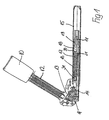
- eine Straffvorrichtung in der Ausbildung als Schloßstraffer in einer geschnittenen Seitenansicht,
- Fig. 2
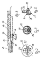
- eine Dichtung in einer Vorderansicht in einer Einzeldarstellung,
- Fig. 3
- ein Gasgeneratorgehäuse mit zugeordnetem Kolben sowie Dichtung entsprechend Figur 1 in einer herausgezogenen Darstellung,
- Fig. 4
- ein weiteres Ausführungsbeispiel der Dichtung gemäß Figur 2 in Einzeldarstellung in Vorderansicht,
- Fig. 5
- den Gegenstand der Figur 4 in einer geschnittenen Seitenansicht.
- Die in Figur 1 dargestellte Straffvorrichtung ist als sogenannter Schloßstraffer ausgebildet, bei welchem ein Sicherheitsgurtschloß 10 als Sicherheitsgurtkomponente gestrafft, also über ein an das Sicherheitsgurtschloß 10 angeschlossenes Seil 11 in Richtung der Straffvorrichtung eingezogen wird. Die Erfindung ist allerdings nicht auf derartige Schloßstraffer beschränkt, vielmehr kann an dem Seil 11 beispielsweise auch eine Gurtschlaufe gehaltert sein, so daß der Sicherheitsgurt unmittelbar gestrafft wird. Das bei dem dargestellten Ausführungsbeispiel als Doppelseil mit zwei parallel zueinander angeordneten Seilsträngen ausgebildete Seil 11 ist über einen fahrzeugfest zu verankernden Umlenkblock 13 geführt, wobei zwischen Umlenkblock 13 und Sicherheitsgurtschloß 10 ein Faltenbalg 12 zur Abdeckung des Seils 11 angeordnet ist. In dem Umlenkblock 13 wird das Seil 11 umgelenkt und geradlinig in ein an den Umlenkblock 13 anschließendes Rohr 15 eingeführt, wobei in dem Umlenkblock 13 eine Exzenterklinke 14 als Rücklaufsperre angeordnet ist, die nach Abschluß der Straffbewegung einen Auszug des Seils 11 aus dem Umlenkblock 13 verhindert.
- In dem die eigentliche Straffvorrichtung beinhaltenden Rohr 15 ist ein Gasgeneratorgehäuse 16 eingesetzt, in welchem ein Gasgenerator 17 angeordnet ist. Der Gasgenerator 17 füllt nur einen Teil des Querschnitts des Gasgeneratorgehäuses 16 aus, wobei durch das Gasgeneratorgehäuse 16 in parallelem Verlauf zum Gasgenerator 17 das Seil 11 hindurchgeführt wird. Auf der dem Umlenkblock 13 abgewandten Seite des Gasgeneratorgehäuses 16 ist ein Druckraum 18 belassen, in den nach Auslösung des Gasgenerators 17 die von diesem erzeugten Gase eintreten. An den Druckraum 18 schließt ein in dem Rohr 15 beweglicher Kolben 19 an, an dem das Seil 11 angeschlagen ist. Zwischen Kolben 19 und Gasgeneratorgehäuse 16 ist ein Distanzstück 20 angeordnet.
- Die Ausbildung der Straffvorrichtung ist dabei so getroffen, daß nach Auslösung des Gasgenerators 17 die von diesem erzeugten Gase den Kolben 19 in dem Rohr 15 antreiben, so daß der Kolben 19 das an ihm festgemachte Seil 11 hinter sich herzieht und so das Sicherheitsgurtschloß 10 strafft.
- Zur Abdichtung des Druckraums 18 gegen die Durchführung des Seils 11 durch das Gasgeneratorgehäuse 16 ist in den Druckraum 18 eine Dichtung 21 eingesetzt, deren Dichtungskörper 22 eine, im vorliegenden Fall für die Hindurchführung des Doppelseils 11 nach Art einer "8" gestaltete Durchtrittsöffnung 23 aufweist, ferner eine Durchtrittsöffnung 24 zur Hindurchführung des über das Gasgeneratorgehäuse 16 vorstehenden Gasgenerators 17, so daß die von diesem erzeugten Gase unmittelbar in den Druckraum 18 eintreten und nicht durch die Dichtung 21 hindurchgeführt werden müssen.
- Wie sich aus Figur 2 entnehmen läßt, ist nach einem ersten Ausführungsbeispiel der Dichtungskörper 22 gegenüber dem Gasgeneratorgehäuse 16 dadurch fixiert und zentriert, daß der Dichtungskörper 22 mit an ihm ausgebildeten Öffnungen 25 auf axial von dem Gasgeneratorgehäuse 16 stirnseitig abstehende Zapfen aufsteckbar ist; hiermit ist auch eine Erleichterung der Montage verbunden.
- In Figur 3 ist ein anderes Ausführungsbeispiel der Anordnung und damit der Montagemöglichkeit für die Dichtung 21 dargestellt, wobei die Dichtung 21 zwischen dem Distanzstück 20 und dem Gasgeneratorgehäuse 16 eingesetzt ist und mit ihrem äußeren Umfang mit Distanzstück 20 und Gasgeneratorgehäuse 16 bündig abschließt und dadurch gegen die Wandung des Rohres 15 anliegt und dichtet.
- Wie sich hierzu aus den Figuren 4 und 5 entnehmen läßt, weist der Dichtungskörper 22 zunächst die Durchtrittsöffnungen 23 und 24 für das Seil 11 und den Gasgenerator 17 auf. Wie näher aus Figur 5 ersichtlich, ist an dem Dichtungskörper 22 in der Verlängerung seiner Durchtrittsöffnung 23 für das Seil 11 ein axial zum Generatorgehäuse 16 vorspringender Vorsprung 26 angeordnet, durch den sich die Durchtrittsöffnung 23 für das Seil 11 erstreckt, wobei sich die Durchtrittsöffnung am Ende des Vorsprunges 26 zu einem Trichter 28 erweitert. Soweit der Dichtungskörper 22 bei der Montage der Straffvorrichtung auf das Seil 11 aufzufädeln ist, wird durch den Trichter 28 das Aufstecken des Dichtungskörpers 22 erleichtert. Die Fixierung und Zentrierung des Dichtungskörpers 22 gegenüber dem Gasgeneratorgehäuse 16 bzw. in dem Rohr 15 ist dadurch verwirklicht, daß das Gasgeneratorgehäuse 16 im Bereich des Vorsprungs 26 einen entsprechend ausgebildeten Rücksprung 27 aufweist.
- Zur Verbesserung der Dichtwirkung des Dichtungskörpers 22 gegenüber dem durch ihn hindurchgeführten Seil 11 im Bereich der Durchtrittsöffnung 23 ist zusätzlich an dem Dichtungskörper 22 ein in Verlängerung der Durchtrittsöffnung 23 axial in den Druckraum 18 vorragender und das hindurchgeführte Seil umschließender Ansatz 29 ausgebildet. Durch den auf den Dichtungskörper 22 nach Auslösung des Gasgenerators 17 einwirkenden Druck wird der Ansatz 29 zusammengedrückt und legt sich dabei zusätzlich abdichtend konzentrisch gegen das hindurchgeführte Seil 11 an. Hierzu ist die Außenfläche 30 des Ansatzes 29 mit einem von dem Dichtungskörper 22 in Richtung auf das Seil 11 geneigten Verlauf ausgebildet.
- Eine entsprechende Dichtwirkung im Bereich der Durchtrittsöffnung 24 für den Gasgenerator 17 ist aus dem Grunde nicht in dem gleichen Maße erforderlich, weil das Gasgeneratorgehäuse 16 an seinem dem Druckraum 18 gegenüberliegenden Ende gegen das Rohr 15 mittels einer zusätzlichen Dichtung 31 abgedichtet ist.
Claims (13)
- Straffvorrichtung für einen Sicherheitsgurt mit einem Rohr (15) zur Führung eines druckgasgetriebenen Kolbens (19) und mit einem an den Kolben (19) angeschlossenen und mit einer zu straffenden Sicherheitsgurtkomponente verbundenen Seil (11), wobei ein der Aufnahme des Gasgenerators (17) dienendes Gasgeneratorgehäuse (16) in dem Rohr (15) angeordnet und zwischen Gasgeneratorgehäuse (16) und Kolben (19) ein Druckraum (18) belassen ist, und wobei das Seil (11) in paralleler Anordnung zum Gasgenerator (17) durch das Gasgeneratorgehäuse (16) und durch den Druckraum (18) bis zum Kolben (19) geführt ist, dadurch gekennzeichnet, daß in dem Rohr (15) eine den Druckraum (18) gegen das Gasgeneratorgehäuse (16) abdichtende und sich bei Druckbeaufschlagung gegen das Gasgeneratorgehäuse (16) abstützende Dichtung (21) angeordnet ist und in dem Dichtungskörper (22) Durchtrittsöffnungen (23, 24) für den aus dem Gasgeneratorgehäuse (16) in den Druckraum (18) vorstehenden Gasgenerator (17) und das Seil (11) angeordnet sind.
- Straffvorrichtung nach Anspruch 1, dadurch gekennzeichnet, daß der Dichtungskörper (22) in Verlängerung der Durchtrittsöffnung (23) für das Seil (11) einen axial in den Druckraum (18) vorragenden und das Seil (11) umschließenden Ansatz (29) aufweist, dessen Außenfläche (30) von dem Dichtungskörper (22) in Richtung auf das Seil (11) geneigt ist.
- Straffvorrichtung nach Anspruch 1 oder 2, dadurch gekennzeichnet, daß der Innendurchmesser der Durchtrittsöffnung (23) für das Seil (11) gleichgroß ist dem Durchmesser des Seils (11).
- Straffvorrichtung nach Anspruch 1 oder 2, dadurch gekennzeichnet, daß der Innendurchmesser der Durchtrittsöffnung (23) für das Seil (11) geringer ist als der Durchmesser des Seils (11).
- Straffvorrichtung nach einem der Ansprüche 1 bis 4, dadurch gekennzeichnet, daß der Dichtungskörper (22) gegenüber dem Gasgeneratorgehäuse (16) zentriert ist.
- Straffvorrichtung nach Anspruch 5, dadurch gekennzeichnet, daß das Gasgeneratorgehäuse (16) axial vorstehende Zapfen und der Dichtungskörper (22) auf die Zapfen aufsteckbare Aufnahmeöffnungen (25) aufweisen.
- Straffvorrichtung nach Anspruch 5, dadurch gekennzeichnet, daß der Dichtungskörper (22) in der Verlängerung seiner Durchtrittsöffnung (23) für das Seil (11) einen axial zum Gasgeneratorgehäuse (16) vorspringenden Vorsprung (26) aufweist und das Gasgeneratorgehäuse (16) in dem von dem Vorsprung (26) des Dichtungskörpers (22) erfaßten Bereich mit einem entsprechenden Rücksprung (27) versehen ist.
- Straffvorrichtung nach Anspruch 7, dadurch gekennzeichnet, daß die sich durch den Vorsprung (26) erstreckende Durchtrittsöffnung (23) für das Seil (11) sich am Ende des Vorsprunges (26) trichterförmig erweitert.
- Straffvorrichtung nach einem der Ansprüche 1 bis 8, dadurch gekennzeichnet, daß zwischen der Komponente (10) des Sicherheitsgurtes und dem Kolben (19) ein Doppelseil angeordnet ist und der Dichtungskörper (22) zwei Durchtrittsöffnungen (23) für die beiden Seile des Doppelseils (11) aufweist.
- Straffvorrichtung nach einem der Ansprüche 1 bis 9, dadurch gekennzeichnet, daß der Dichtungskörper (22) auf seinem äußeren, gegen die Wandung des Rohres (15) anliegenden Umfang eine Dichtlippe aufweist.
- Straffvorrichtung nach einem der Ansprüche 1 bis 10, dadurch gekennzeichnet, daß der Dichtungskörper aus einem elastischen Material besteht.
- Straffvorrichtung nach einem der Ansprüche 1 bis 11, dadurch gekennzeichnet, daß der Dichtungskörper aus Kunststoff besteht.
- Straffvorrichtung nach einem der Ansprüche 1 bis 12, dadurch gekennzeichnet, daß das Gasgeneratorgehäuse (16) an seinem dem Druckraum (18) gegenüberliegenden Ende gegen das Rohr (15) abgedichtet ist.
Applications Claiming Priority (3)
| Application Number | Priority Date | Filing Date | Title |
|---|---|---|---|
| DE10228617 | 2002-06-26 | ||
| DE10228617 | 2002-06-26 | ||
| PCT/EP2003/006226 WO2004002785A1 (de) | 2002-06-26 | 2003-06-13 | Straffvorrichtung mit einem abgedichteten gasgeneratorgehäuse |
Publications (2)
| Publication Number | Publication Date |
|---|---|
| EP1515878A1 EP1515878A1 (de) | 2005-03-23 |
| EP1515878B1 true EP1515878B1 (de) | 2006-05-17 |
Family
ID=29795891
Family Applications (1)
| Application Number | Title | Priority Date | Filing Date |
|---|---|---|---|
| EP03761460A Expired - Lifetime EP1515878B1 (de) | 2002-06-26 | 2003-06-13 | Straffvorrichtung mit einem abgedichteten gasgeneratorgehäuse |
Country Status (7)
| Country | Link |
|---|---|
| EP (1) | EP1515878B1 (de) |
| JP (1) | JP4022545B2 (de) |
| AT (1) | ATE326371T1 (de) |
| AU (1) | AU2003279672A1 (de) |
| DE (1) | DE50303376D1 (de) |
| ES (1) | ES2264005T3 (de) |
| WO (1) | WO2004002785A1 (de) |
Families Citing this family (5)
| Publication number | Priority date | Publication date | Assignee | Title |
|---|---|---|---|---|
| DE102005008108B4 (de) * | 2004-02-24 | 2007-08-09 | Delphi Technologies, Inc., Troy | Gurtstraffersystem für Kraftfahrzeuge |
| DE102005006999A1 (de) * | 2005-02-16 | 2006-08-17 | Autoliv Development Ab | Doppelseil-Straffvorrichtung für einen Sicherheitsgurt |
| US7380832B2 (en) | 2005-04-05 | 2008-06-03 | Takata Seat Belts, Inc. | Pretensioner with integrated gas generator |
| JP4863284B2 (ja) * | 2007-02-28 | 2012-01-25 | タカタ株式会社 | プリテンショナ及びシートベルト装置 |
| CN103223919A (zh) * | 2013-05-08 | 2013-07-31 | 黄绍勇 | 一种汽车安全带预紧器 |
Family Cites Families (3)
| Publication number | Priority date | Publication date | Assignee | Title |
|---|---|---|---|---|
| DE29609054U1 (de) * | 1996-05-20 | 1996-09-19 | Trw Occupant Restraint Systems Gmbh, 73551 Alfdorf | Gurtstraffer für ein Fahrzeuginsassen-Rückhaltesystem |
| US6036274A (en) * | 1997-11-13 | 2000-03-14 | Breed Automotive Technology, Inc. | Drive pulley, compact buckle pretensioner |
| WO1999058377A1 (en) * | 1998-05-08 | 1999-11-18 | Breed Automotive Technology, Inc. | Pretensioner |
-
2003
- 2003-06-13 DE DE50303376T patent/DE50303376D1/de not_active Expired - Lifetime
- 2003-06-13 EP EP03761460A patent/EP1515878B1/de not_active Expired - Lifetime
- 2003-06-13 WO PCT/EP2003/006226 patent/WO2004002785A1/de not_active Ceased
- 2003-06-13 AT AT03761460T patent/ATE326371T1/de not_active IP Right Cessation
- 2003-06-13 JP JP2004516587A patent/JP4022545B2/ja not_active Expired - Fee Related
- 2003-06-13 ES ES03761460T patent/ES2264005T3/es not_active Expired - Lifetime
- 2003-06-13 AU AU2003279672A patent/AU2003279672A1/en not_active Abandoned
Also Published As
| Publication number | Publication date |
|---|---|
| JP4022545B2 (ja) | 2007-12-19 |
| WO2004002785A1 (de) | 2004-01-08 |
| ATE326371T1 (de) | 2006-06-15 |
| JP2005530651A (ja) | 2005-10-13 |
| EP1515878A1 (de) | 2005-03-23 |
| ES2264005T3 (es) | 2006-12-16 |
| AU2003279672A1 (en) | 2004-01-19 |
| DE50303376D1 (de) | 2006-06-22 |
Similar Documents
| Publication | Publication Date | Title |
|---|---|---|
| DE69210165T2 (de) | Feuchtigkeitsbeständige Kabelverbindung und dazugehörige Dichtungsstruktur | |
| DE19918596B4 (de) | Vorrichtung zum Straffen eines Sicherheitsgurtes | |
| DE69626094T2 (de) | Sicherheitsgurtstrammer | |
| DE69901568T2 (de) | Vorrichtung zur abdichtung eine leckage in einer rohrleitung | |
| DE102014002006A1 (de) | Straffer für eine Fahrzeugsicherheitseinrichtung | |
| DE102015111083B4 (de) | Straffvorrichtung mit Dichtungsvorrichtung | |
| DE2515939A1 (de) | Thermoplastklemmuffe mit dichtungskoerper | |
| DE1958458B2 (de) | Keilverankerung für Spannglieder mit einem Ankerkörper | |
| DE3400115C2 (de) | ||
| EP3642084A1 (de) | Sicherheitsgurteinrichtung für ein fahrzeug | |
| WO2021160569A1 (de) | Straffvorrichtung für eine sicherheitsgurtkomponente | |
| DE2620123A1 (de) | Kombinierte anschluss- und absperrvorrichtung | |
| DE102009055998B4 (de) | Gurtstraffer mit ringförmigem Antriebskolben | |
| EP1761417A1 (de) | Sicherheitsgurt-straffeinrichtung mit einem eine engstelle aufweisenden rohr | |
| DE29806199U1 (de) | Gurtstraffer mit Linearantrieb | |
| WO2004002785A1 (de) | Straffvorrichtung mit einem abgedichteten gasgeneratorgehäuse | |
| DE102007046715B3 (de) | Seilstraffer mit einer sich funktionsbedingt trennenden Seilabdichtung | |
| EP1737711B1 (de) | Seilstraffer mit zweifachem seileinlauf | |
| DE102005058545B3 (de) | Seilstraffer mit einer Seilabdichtung | |
| DE102023106842A1 (de) | Straffvorrichtung für eine Sicherheitsgurtkomponente | |
| DE102006002731B3 (de) | Seilstraffer mit einer eine Kraftbegrenzungsfunktion aufweisenden Seilabdichtung | |
| DE20303115U1 (de) | Insassenschutzeinrichtung | |
| DE102016104226A1 (de) | Straffvorrichtung für einen Sicherheitsgurt mit einem Leitelement | |
| DE3503188A1 (de) | Strammvorrichtung fuer sicherheitsgurte in kraftfahrzeugen | |
| DE102022122770B4 (de) | Straffvorrichtung für eine Sicherheitsgurtkomponente |
Legal Events
| Date | Code | Title | Description |
|---|---|---|---|
| PUAI | Public reference made under article 153(3) epc to a published international application that has entered the european phase |
Free format text: ORIGINAL CODE: 0009012 |
|
| 17P | Request for examination filed |
Effective date: 20041203 |
|
| AK | Designated contracting states |
Kind code of ref document: A1 Designated state(s): AT BE BG CH CY CZ DE DK EE ES FI FR GB GR HU IE IT LI LU MC NL PT RO SE SI SK TR |
|
| AX | Request for extension of the european patent |
Extension state: AL LT LV MK |
|
| DAX | Request for extension of the european patent (deleted) | ||
| GRAP | Despatch of communication of intention to grant a patent |
Free format text: ORIGINAL CODE: EPIDOSNIGR1 |
|
| GRAS | Grant fee paid |
Free format text: ORIGINAL CODE: EPIDOSNIGR3 |
|
| GRAA | (expected) grant |
Free format text: ORIGINAL CODE: 0009210 |
|
| AK | Designated contracting states |
Kind code of ref document: B1 Designated state(s): AT BE BG CH CY CZ DE DK EE ES FI FR GB GR HU IE IT LI LU MC NL PT RO SE SI SK TR |
|
| PG25 | Lapsed in a contracting state [announced via postgrant information from national office to epo] |
Ref country code: GB Free format text: LAPSE BECAUSE OF FAILURE TO SUBMIT A TRANSLATION OF THE DESCRIPTION OR TO PAY THE FEE WITHIN THE PRESCRIBED TIME-LIMIT Effective date: 20060517 Ref country code: SI Free format text: LAPSE BECAUSE OF FAILURE TO SUBMIT A TRANSLATION OF THE DESCRIPTION OR TO PAY THE FEE WITHIN THE PRESCRIBED TIME-LIMIT Effective date: 20060517 Ref country code: CZ Free format text: LAPSE BECAUSE OF FAILURE TO SUBMIT A TRANSLATION OF THE DESCRIPTION OR TO PAY THE FEE WITHIN THE PRESCRIBED TIME-LIMIT Effective date: 20060517 Ref country code: FI Free format text: LAPSE BECAUSE OF FAILURE TO SUBMIT A TRANSLATION OF THE DESCRIPTION OR TO PAY THE FEE WITHIN THE PRESCRIBED TIME-LIMIT Effective date: 20060517 Ref country code: SK Free format text: LAPSE BECAUSE OF FAILURE TO SUBMIT A TRANSLATION OF THE DESCRIPTION OR TO PAY THE FEE WITHIN THE PRESCRIBED TIME-LIMIT Effective date: 20060517 Ref country code: NL Free format text: LAPSE BECAUSE OF FAILURE TO SUBMIT A TRANSLATION OF THE DESCRIPTION OR TO PAY THE FEE WITHIN THE PRESCRIBED TIME-LIMIT Effective date: 20060517 Ref country code: IE Free format text: LAPSE BECAUSE OF FAILURE TO SUBMIT A TRANSLATION OF THE DESCRIPTION OR TO PAY THE FEE WITHIN THE PRESCRIBED TIME-LIMIT Effective date: 20060517 Ref country code: RO Free format text: LAPSE BECAUSE OF FAILURE TO SUBMIT A TRANSLATION OF THE DESCRIPTION OR TO PAY THE FEE WITHIN THE PRESCRIBED TIME-LIMIT Effective date: 20060517 |
|
| REG | Reference to a national code |
Ref country code: GB Ref legal event code: FG4D Free format text: NOT ENGLISH |
|
| REG | Reference to a national code |
Ref country code: CH Ref legal event code: EP |
|
| REG | Reference to a national code |
Ref country code: IE Ref legal event code: FG4D Free format text: LANGUAGE OF EP DOCUMENT: GERMAN |
|
| REF | Corresponds to: |
Ref document number: 50303376 Country of ref document: DE Date of ref document: 20060622 Kind code of ref document: P |
|
| PG25 | Lapsed in a contracting state [announced via postgrant information from national office to epo] |
Ref country code: MC Free format text: LAPSE BECAUSE OF NON-PAYMENT OF DUE FEES Effective date: 20060630 Ref country code: BE Free format text: LAPSE BECAUSE OF NON-PAYMENT OF DUE FEES Effective date: 20060630 |
|
| PG25 | Lapsed in a contracting state [announced via postgrant information from national office to epo] |
Ref country code: SE Free format text: LAPSE BECAUSE OF FAILURE TO SUBMIT A TRANSLATION OF THE DESCRIPTION OR TO PAY THE FEE WITHIN THE PRESCRIBED TIME-LIMIT Effective date: 20060817 Ref country code: DK Free format text: LAPSE BECAUSE OF FAILURE TO SUBMIT A TRANSLATION OF THE DESCRIPTION OR TO PAY THE FEE WITHIN THE PRESCRIBED TIME-LIMIT Effective date: 20060817 |
|
| PG25 | Lapsed in a contracting state [announced via postgrant information from national office to epo] |
Ref country code: PT Free format text: LAPSE BECAUSE OF FAILURE TO SUBMIT A TRANSLATION OF THE DESCRIPTION OR TO PAY THE FEE WITHIN THE PRESCRIBED TIME-LIMIT Effective date: 20061017 |
|
| NLV1 | Nl: lapsed or annulled due to failure to fulfill the requirements of art. 29p and 29m of the patents act | ||
| GBV | Gb: ep patent (uk) treated as always having been void in accordance with gb section 77(7)/1977 [no translation filed] |
Effective date: 20060517 |
|
| REG | Reference to a national code |
Ref country code: ES Ref legal event code: FG2A Ref document number: 2264005 Country of ref document: ES Kind code of ref document: T3 |
|
| ET | Fr: translation filed | ||
| REG | Reference to a national code |
Ref country code: IE Ref legal event code: FD4D |
|
| PLBE | No opposition filed within time limit |
Free format text: ORIGINAL CODE: 0009261 |
|
| STAA | Information on the status of an ep patent application or granted ep patent |
Free format text: STATUS: NO OPPOSITION FILED WITHIN TIME LIMIT |
|
| 26N | No opposition filed |
Effective date: 20070220 |
|
| PG25 | Lapsed in a contracting state [announced via postgrant information from national office to epo] |
Ref country code: AT Free format text: LAPSE BECAUSE OF NON-PAYMENT OF DUE FEES Effective date: 20060613 |
|
| BERE | Be: lapsed |
Owner name: AUTOLIV DEVELOPMENT A.B. Effective date: 20060630 |
|
| REG | Reference to a national code |
Ref country code: CH Ref legal event code: PL |
|
| PG25 | Lapsed in a contracting state [announced via postgrant information from national office to epo] |
Ref country code: LI Free format text: LAPSE BECAUSE OF NON-PAYMENT OF DUE FEES Effective date: 20070630 Ref country code: CH Free format text: LAPSE BECAUSE OF NON-PAYMENT OF DUE FEES Effective date: 20070630 Ref country code: GR Free format text: LAPSE BECAUSE OF FAILURE TO SUBMIT A TRANSLATION OF THE DESCRIPTION OR TO PAY THE FEE WITHIN THE PRESCRIBED TIME-LIMIT Effective date: 20060818 |
|
| PG25 | Lapsed in a contracting state [announced via postgrant information from national office to epo] |
Ref country code: BG Free format text: LAPSE BECAUSE OF FAILURE TO SUBMIT A TRANSLATION OF THE DESCRIPTION OR TO PAY THE FEE WITHIN THE PRESCRIBED TIME-LIMIT Effective date: 20060817 Ref country code: EE Free format text: LAPSE BECAUSE OF FAILURE TO SUBMIT A TRANSLATION OF THE DESCRIPTION OR TO PAY THE FEE WITHIN THE PRESCRIBED TIME-LIMIT Effective date: 20060517 |
|
| PG25 | Lapsed in a contracting state [announced via postgrant information from national office to epo] |
Ref country code: HU Free format text: LAPSE BECAUSE OF FAILURE TO SUBMIT A TRANSLATION OF THE DESCRIPTION OR TO PAY THE FEE WITHIN THE PRESCRIBED TIME-LIMIT Effective date: 20061118 Ref country code: LU Free format text: LAPSE BECAUSE OF NON-PAYMENT OF DUE FEES Effective date: 20060613 Ref country code: TR Free format text: LAPSE BECAUSE OF FAILURE TO SUBMIT A TRANSLATION OF THE DESCRIPTION OR TO PAY THE FEE WITHIN THE PRESCRIBED TIME-LIMIT Effective date: 20060517 |
|
| PG25 | Lapsed in a contracting state [announced via postgrant information from national office to epo] |
Ref country code: CY Free format text: LAPSE BECAUSE OF FAILURE TO SUBMIT A TRANSLATION OF THE DESCRIPTION OR TO PAY THE FEE WITHIN THE PRESCRIBED TIME-LIMIT Effective date: 20060517 |
|
| PG25 | Lapsed in a contracting state [announced via postgrant information from national office to epo] |
Ref country code: IT Free format text: LAPSE BECAUSE OF NON-PAYMENT OF DUE FEES Effective date: 20090613 |
|
| PGRI | Patent reinstated in contracting state [announced from national office to epo] |
Ref country code: IT Effective date: 20110616 |
|
| PGFP | Annual fee paid to national office [announced via postgrant information from national office to epo] |
Ref country code: IT Payment date: 20120611 Year of fee payment: 10 |
|
| PGFP | Annual fee paid to national office [announced via postgrant information from national office to epo] |
Ref country code: ES Payment date: 20120618 Year of fee payment: 10 |
|
| PG25 | Lapsed in a contracting state [announced via postgrant information from national office to epo] |
Ref country code: IT Free format text: LAPSE BECAUSE OF NON-PAYMENT OF DUE FEES Effective date: 20130613 |
|
| REG | Reference to a national code |
Ref country code: ES Ref legal event code: FD2A Effective date: 20140707 |
|
| PG25 | Lapsed in a contracting state [announced via postgrant information from national office to epo] |
Ref country code: ES Free format text: LAPSE BECAUSE OF NON-PAYMENT OF DUE FEES Effective date: 20130614 |
|
| REG | Reference to a national code |
Ref country code: FR Ref legal event code: PLFP Year of fee payment: 13 |
|
| PGFP | Annual fee paid to national office [announced via postgrant information from national office to epo] |
Ref country code: DE Payment date: 20150413 Year of fee payment: 13 |
|
| PGFP | Annual fee paid to national office [announced via postgrant information from national office to epo] |
Ref country code: FR Payment date: 20150406 Year of fee payment: 13 |
|
| REG | Reference to a national code |
Ref country code: DE Ref legal event code: R119 Ref document number: 50303376 Country of ref document: DE |
|
| REG | Reference to a national code |
Ref country code: FR Ref legal event code: ST Effective date: 20170228 |
|
| PG25 | Lapsed in a contracting state [announced via postgrant information from national office to epo] |
Ref country code: DE Free format text: LAPSE BECAUSE OF NON-PAYMENT OF DUE FEES Effective date: 20170103 Ref country code: FR Free format text: LAPSE BECAUSE OF NON-PAYMENT OF DUE FEES Effective date: 20160630 |