EP1515399A2 - Anisotropic conductive film, production method thereof and method of use thereof - Google Patents
Anisotropic conductive film, production method thereof and method of use thereof Download PDFInfo
- Publication number
- EP1515399A2 EP1515399A2 EP04021330A EP04021330A EP1515399A2 EP 1515399 A2 EP1515399 A2 EP 1515399A2 EP 04021330 A EP04021330 A EP 04021330A EP 04021330 A EP04021330 A EP 04021330A EP 1515399 A2 EP1515399 A2 EP 1515399A2
- Authority
- EP
- European Patent Office
- Prior art keywords
- film
- conductive
- conductive paths
- anisotropic conductive
- electronic component
- Prior art date
- Legal status (The legal status is an assumption and is not a legal conclusion. Google has not performed a legal analysis and makes no representation as to the accuracy of the status listed.)
- Granted
Links
Images


Classifications
-
- H—ELECTRICITY
- H01—ELECTRIC ELEMENTS
- H01R—ELECTRICALLY-CONDUCTIVE CONNECTIONS; STRUCTURAL ASSOCIATIONS OF A PLURALITY OF MUTUALLY-INSULATED ELECTRICAL CONNECTING ELEMENTS; COUPLING DEVICES; CURRENT COLLECTORS
- H01R11/00—Individual connecting elements providing two or more spaced connecting locations for conductive members which are, or may be, thereby interconnected, e.g. end pieces for wires or cables supported by the wire or cable and having means for facilitating electrical connection to some other wire, terminal, or conductive member, blocks of binding posts
- H01R11/01—Individual connecting elements providing two or more spaced connecting locations for conductive members which are, or may be, thereby interconnected, e.g. end pieces for wires or cables supported by the wire or cable and having means for facilitating electrical connection to some other wire, terminal, or conductive member, blocks of binding posts characterised by the form or arrangement of the conductive interconnection between the connecting locations
-
- H—ELECTRICITY
- H01—ELECTRIC ELEMENTS
- H01R—ELECTRICALLY-CONDUCTIVE CONNECTIONS; STRUCTURAL ASSOCIATIONS OF A PLURALITY OF MUTUALLY-INSULATED ELECTRICAL CONNECTING ELEMENTS; COUPLING DEVICES; CURRENT COLLECTORS
- H01R13/00—Details of coupling devices of the kinds covered by groups H01R12/70 or H01R24/00 - H01R33/00
- H01R13/02—Contact members
- H01R13/22—Contacts for co-operating by abutting
- H01R13/24—Contacts for co-operating by abutting resilient; resiliently-mounted
- H01R13/2407—Contacts for co-operating by abutting resilient; resiliently-mounted characterized by the resilient means
- H01R13/2414—Contacts for co-operating by abutting resilient; resiliently-mounted characterized by the resilient means conductive elastomers
-
- G—PHYSICS
- G01—MEASURING; TESTING
- G01R—MEASURING ELECTRIC VARIABLES; MEASURING MAGNETIC VARIABLES
- G01R1/00—Details of instruments or arrangements of the types included in groups G01R5/00 - G01R13/00 and G01R31/00
- G01R1/02—General constructional details
- G01R1/06—Measuring leads; Measuring probes
- G01R1/067—Measuring probes
- G01R1/073—Multiple probes
- G01R1/07307—Multiple probes with individual probe elements, e.g. needles, cantilever beams or bump contacts, fixed in relation to each other, e.g. bed of nails fixture or probe card
- G01R1/07364—Multiple probes with individual probe elements, e.g. needles, cantilever beams or bump contacts, fixed in relation to each other, e.g. bed of nails fixture or probe card with provisions for altering position, number or connection of probe tips; Adapting to differences in pitch
- G01R1/07371—Multiple probes with individual probe elements, e.g. needles, cantilever beams or bump contacts, fixed in relation to each other, e.g. bed of nails fixture or probe card with provisions for altering position, number or connection of probe tips; Adapting to differences in pitch using an intermediate card or back card with apertures through which the probes pass
-
- H—ELECTRICITY
- H01—ELECTRIC ELEMENTS
- H01R—ELECTRICALLY-CONDUCTIVE CONNECTIONS; STRUCTURAL ASSOCIATIONS OF A PLURALITY OF MUTUALLY-INSULATED ELECTRICAL CONNECTING ELEMENTS; COUPLING DEVICES; CURRENT COLLECTORS
- H01R43/00—Apparatus or processes specially adapted for manufacturing, assembling, maintaining, or repairing of line connectors or current collectors or for joining electric conductors
-
- H—ELECTRICITY
- H10—SEMICONDUCTOR DEVICES; ELECTRIC SOLID-STATE DEVICES NOT OTHERWISE PROVIDED FOR
- H10W—GENERIC PACKAGES, INTERCONNECTIONS, CONNECTORS OR OTHER CONSTRUCTIONAL DETAILS OF DEVICES COVERED BY CLASS H10
- H10W70/00—Package substrates; Interposers; Redistribution layers [RDL]
- H10W70/01—Manufacture or treatment
- H10W70/05—Manufacture or treatment of insulating or insulated package substrates, or of interposers, or of redistribution layers
- H10W70/095—Manufacture or treatment of insulating or insulated package substrates, or of interposers, or of redistribution layers of vias therein
-
- H—ELECTRICITY
- H10—SEMICONDUCTOR DEVICES; ELECTRIC SOLID-STATE DEVICES NOT OTHERWISE PROVIDED FOR
- H10W—GENERIC PACKAGES, INTERCONNECTIONS, CONNECTORS OR OTHER CONSTRUCTIONAL DETAILS OF DEVICES COVERED BY CLASS H10
- H10W70/00—Package substrates; Interposers; Redistribution layers [RDL]
- H10W70/60—Insulating or insulated package substrates; Interposers; Redistribution layers
- H10W70/62—Insulating or insulated package substrates; Interposers; Redistribution layers characterised by their interconnections
- H10W70/63—Vias, e.g. via plugs
- H10W70/635—Through-vias
-
- H—ELECTRICITY
- H10—SEMICONDUCTOR DEVICES; ELECTRIC SOLID-STATE DEVICES NOT OTHERWISE PROVIDED FOR
- H10W—GENERIC PACKAGES, INTERCONNECTIONS, CONNECTORS OR OTHER CONSTRUCTIONAL DETAILS OF DEVICES COVERED BY CLASS H10
- H10W72/00—Interconnections or connectors in packages
- H10W72/30—Die-attach connectors
-
- G—PHYSICS
- G01—MEASURING; TESTING
- G01R—MEASURING ELECTRIC VARIABLES; MEASURING MAGNETIC VARIABLES
- G01R1/00—Details of instruments or arrangements of the types included in groups G01R5/00 - G01R13/00 and G01R31/00
- G01R1/02—General constructional details
- G01R1/06—Measuring leads; Measuring probes
- G01R1/067—Measuring probes
- G01R1/073—Multiple probes
- G01R1/07307—Multiple probes with individual probe elements, e.g. needles, cantilever beams or bump contacts, fixed in relation to each other, e.g. bed of nails fixture or probe card
- G01R1/0735—Multiple probes with individual probe elements, e.g. needles, cantilever beams or bump contacts, fixed in relation to each other, e.g. bed of nails fixture or probe card arranged on a flexible frame or film
-
- G—PHYSICS
- G01—MEASURING; TESTING
- G01R—MEASURING ELECTRIC VARIABLES; MEASURING MAGNETIC VARIABLES
- G01R3/00—Apparatus or processes specially adapted for the manufacture or maintenance of measuring instruments, e.g. of probe tips
-
- H—ELECTRICITY
- H10—SEMICONDUCTOR DEVICES; ELECTRIC SOLID-STATE DEVICES NOT OTHERWISE PROVIDED FOR
- H10W—GENERIC PACKAGES, INTERCONNECTIONS, CONNECTORS OR OTHER CONSTRUCTIONAL DETAILS OF DEVICES COVERED BY CLASS H10
- H10W72/00—Interconnections or connectors in packages
- H10W72/01—Manufacture or treatment
- H10W72/012—Manufacture or treatment of bump connectors, dummy bumps or thermal bumps
- H10W72/01212—Manufacture or treatment of bump connectors, dummy bumps or thermal bumps at a different location than on the final device, e.g. forming as prepeg
-
- H—ELECTRICITY
- H10—SEMICONDUCTOR DEVICES; ELECTRIC SOLID-STATE DEVICES NOT OTHERWISE PROVIDED FOR
- H10W—GENERIC PACKAGES, INTERCONNECTIONS, CONNECTORS OR OTHER CONSTRUCTIONAL DETAILS OF DEVICES COVERED BY CLASS H10
- H10W72/00—Interconnections or connectors in packages
- H10W72/071—Connecting or disconnecting
- H10W72/072—Connecting or disconnecting of bump connectors
-
- H—ELECTRICITY
- H10—SEMICONDUCTOR DEVICES; ELECTRIC SOLID-STATE DEVICES NOT OTHERWISE PROVIDED FOR
- H10W—GENERIC PACKAGES, INTERCONNECTIONS, CONNECTORS OR OTHER CONSTRUCTIONAL DETAILS OF DEVICES COVERED BY CLASS H10
- H10W72/00—Interconnections or connectors in packages
- H10W72/071—Connecting or disconnecting
- H10W72/073—Connecting or disconnecting of die-attach connectors
- H10W72/07331—Connecting techniques
-
- H—ELECTRICITY
- H10—SEMICONDUCTOR DEVICES; ELECTRIC SOLID-STATE DEVICES NOT OTHERWISE PROVIDED FOR
- H10W—GENERIC PACKAGES, INTERCONNECTIONS, CONNECTORS OR OTHER CONSTRUCTIONAL DETAILS OF DEVICES COVERED BY CLASS H10
- H10W72/00—Interconnections or connectors in packages
- H10W72/30—Die-attach connectors
- H10W72/351—Materials of die-attach connectors
- H10W72/353—Materials of die-attach connectors not comprising solid metals or solid metalloids, e.g. ceramics
- H10W72/354—Materials of die-attach connectors not comprising solid metals or solid metalloids, e.g. ceramics comprising polymers
Definitions
- the present invention relates to an anisotropic conductive film, a production method thereof and a test method of an electronic component using the same.
- an anisotropic conductive connector For an electrical connection between an electronic component such as a semiconductor element (IC chip) and the like and a circuit board, an anisotropic conductive connector has been widely used in recent years.
- an anisotropic conductive connector one prepared by dispersing conductive fine particles in an insulating film has been conventionally known.
- This anisotropic conductive connector is associated with problems of structurally difficult connection with a connection target having a fine pitch and the need for forming a terminal of the connection target, such as electrode of semiconductor element and the like in a protrusion (bump).
- an anisotropic conductive connector capable of resolving such problems, namely, an anisotropic conductive connector capable of dealing with finely pitched and bumpless target
- the Applicant of this invention has proposed an anisotropic conductive connector (film) comprising, in the substrate of an insulating film, plural conductive paths penetrating in the thickness direction of the film substrate while being insulated from each other, in international publication WO98/07216 (US Patent No. 6,245,175).
- anisotropic conductive connectors have been employed for the following two uses.
- a mounting connector wherein an anisotropic conductive connector is disposed between an electronic component such as a semiconductor element and the like and a circuit board, which, upon heating and pressing, electrically and mechanically connects the electronic component and the circuit board.
- a test connector wherein, in functional tests of electronic components such as semiconductor element and the like, an anisotropic conductive connector is inserted between an electronic component and a circuit board, which, upon press adhesion to the both, achieves a functionally testable conduction between the electronic component and the circuit board.
- anisotropic conductive connector as a test connector is necessary because a functional test of an electronic component after mounting the electronic component on a circuit board only to prove that the electronic component is defective results in disposal of a good circuit board together with the component, thereby lowering the production efficiency of the circuit board and increasing an economical loss.
- a probe pin In a conduction test of a semiconductor element, an electronic component and a circuit board, a probe pin has been used conventionally, but a probe exclusive for each test subject component needs to be made because the position of an electrode differs for each test subject component.
- the size of an electronic component and an electrode of a circuit board as well as distance between electrodes have been reduced, which makes production of a probe pin problematically difficult or costly.
- the use of an anisotropic conductive film has been proposed for conduction test of an electronic component and the like.
- an anisotropic conductive film When an anisotropic conductive film is used as a test connector, a load for electric conduction between an electronic component and a circuit board is preferably as small as possible, in view of improved efficiency of test operation and prevention of terminal damage and deformation of an electronic component and a circuit board. To achieve this, an anisotropic conductive film is required to have flexibility permitting followability to the surface shape of an electronic component and a circuit board. On the other hand, when an anisotropic conductive film is used as a mounting connector, it is required to achieve not only easy contact of a conductive path of the connector to the terminal of a connection target such as an electronic component, a circuit board and the like, but also sufficient adhesion of the connector to a connection target.
- a connection target such as an electronic component, a circuit board and the like
- the anisotropic conductive film proposed in WO98/07216 is produced by a method comprising winding an insulated conductive wire (metal wire coated with insulating resin layer) multiple times around a core, bonding coating layers to prevent separation from each other to give a winding block, and cutting this block in a desired thickness along the plane forming an angle with each insulated conductive wire (metal wire). Therefore, increase of the proportion of a resin in an anisotropic conductive film has been difficult.
- the thickness of an insulating resin layer of an insulated conductive wire cannot be increased beyond a certain level, and therefore, the proportion of a resin in an anisotropic conductive film cannot be increased sufficiently.
- the present Applicant has proposed, as a method for producing an anisotropic conductive film having a sufficiently increased proportion of a resin, a method comprising cutting out a film from a block having a multilayer structure achieved by alternately winding a layer of wound wire comprising an insulated conductive wire and an insulating resin film around a core (JP-A-2002-42921).
- the anisotropic conductive film disclosed in JP-A-2002-42921 aims only at increasing the proportion of a resin in a film, the distance between adjacent conductive paths (proportion of insulated area) in an anisotropic conductive film becomes too large, which makes sufficient application thereof to a narrow pitch terminal of a connection target (electronic component, circuit board) unattainable.
- some of the electronic components have terminals disposed at a narrow pitch, and in some cases, the surface of a terminal disposed at a narrow pitch is far back from the surface of the body of the component.
- the present inventors have found that, when an anisotropic conductive film is to be used, problems occur such as a contact failure between electrodes, "staining of metal electrode” and the like in a conduction test of an electronic component at a high temperature. Even when a simple conduction test using an electrically conductive rubber is conducted, a problem of failure to mount an electronic component and a circuit board occurs.
- the present invention mainly aims at providing an anisotropic conductive film affording a fine contact between a terminal of a connection target and a conductive path by simply applying a relatively low load to a connection target having a narrow-pitched terminal, particularly a connection target having a narrow pitch and a terminal disposed far back from the surface of the component and a production method thereof.
- the present invention mainly aims at providing an anisotropic conductive film for an electronic component test, which is unlikely to stain an electrode of a test subject electronic component and the surface of a circuit pattern of a circuit board, in a wide temperature range of from 20°C to 150°C.
- the present invention also aims at providing a highly reliable test method of an electronic component using an anisotropic conductive film.
- the present inventors have conducted intensive studies in an attempt to solve the aforementioned problems and found that an anisotropic conductive film showing relatively high flexibility even in the presence of highly densely disposed conductive paths can be obtained by arranging conductive paths in a houndstooth check pattern, and decreasing the distance between conductive paths between rows of conductive paths rather than the distance between conductive paths within a row of conductive paths.
- a conductive path arranged as mentioned above should be protruded from the principal plane of a film substrate, and preferably inclined such that a centerline thereof forms an angle of 5 - 45° with the vertical line of the principal plane of the film substrate.
- the present inventors have also found that the pollution of a metal electrode is caused by adhesion of a low molecular weight component generated from an anisotropic conductive film and a silicone component from an electrically conductive rubber (made of silicone) to the above-mentioned metal electrode. Based on these findings, the present inventors have further conducted intensive studies and completed the present invention directed to the following.
- the present invention relates to
- the anisotropic conductive film of the present invention comprises a film substrate comprising an insulating resin and plural conductive paths insulated from each other and penetrating the film substrate in the thickness direction.
- Fig. 1 schematically shows a first embodiment of the anisotropic conductive film of the present invention, wherein Fig. 1(a) is a plane view, and Fig. 1(b) is a sectional view of Fig. 1(a) along line I-I.
- conductive paths 1 form rows of conductive paths (10A - 1, 10A - 2, 10A - 3, 10A - 4, ⁇ ) arranged in parallel to each other at a given pitch in one direction (e.g., direction Y in Fig. 1) of the principal plane of the film, and the position of respective conductive paths 1 constituting the odd-numbered rows of conductive paths (10A - 1, 10A - 3, ⁇ ) is out of alignment by about 1/2 pitch toward the aligning direction (direction X in Fig. 1) of the conductive path 1 from the position of respective conductive paths 1 constituting the even-numbered rows of conductive paths (10A - 2, 10A - 4, ⁇ ), as counted from the outermost end of the film.
- distance between conductive paths within a row of conductive paths is meant, when conductive paths are aligned at a given pitch to constitute rows of conductive paths, the distance between the centerlines of adjacent conductive paths in the rows of conductive paths, which is shown by, for example, D1 and D3 in Fig. 1.
- distance between conductive paths between adjacent rows of conductive paths is meant the distance between any one conductive path in any row of conductive paths and a conductive path in a row of conductive paths adjacent to the aforementioned row of conductive paths, which is the nearest to the aforementioned conductive path, which is shown by, for example, D2, D4 in Fig. 1.
- a film substrate 2 made from an insulating resin comprises plural conductive paths 1 insulated from each other and penetrating the film substrate 2 in the thickness direction.
- plural conductive paths 1 are disposed to form a houndtooth check pattern and the distance between conductive paths (D2) between adjacent rows of conductive paths is smaller than the distance between conductive paths (pitch) (D1) within a row of conductive paths (10A - 1, 10A - 2, 10A - 3, 10A - 4 ⁇ ).
- the above-mentioned particular positional relationship between conductive paths in the adjacent rows of conductive paths is preferably realized not only between plural rows of conductive paths disposed in parallel to each other in one direction (first direction) of the principal plane in a film (e.g., plural rows of conductive paths 10A - 1, 10A - 2, 10A - 3, 10A - 4 ⁇ arranged in parallel to direction Y in Fig. 1), but also in plural rows of conductive paths disposed in parallel to each other in the direction perpendicular to the first direction (second direction) in the principal plane of the film (e.g., plural rows of conductive paths 10B - 1, 10B - 2, 10B - 3, 10B - 4 ⁇ aligned in direction X in Fig. 1).
- a flexible anisotropic conductive film having conductive paths at a relatively high density can be obtained.
- a conductive path of such anisotropic conductive film certainly comes into contact with a narrow pitched terminal disposed on a connection target (electronic component, circuit board) by merely applying a load of a relatively low pressure. Therefore, the anisotropic conductive film of this embodiment can be used as a test connector. Since such anisotropic conductive film certainly adheres to an electronic component and a circuit board, it can be used as a mounting connector capable of mounting an electronic component having a narrow pitched terminal on a circuit board in an electrically and mechanically fine manner.
- the outer diameter (thickness) of the conductive path 1 is preferably not more than 60 ⁇ m, more preferably not more than 30 ⁇ m.
- the distance between conductive paths within a row of conductive paths (distance between the centerlines of conductive paths) as shown by D1 and D3 in Fig. 1(a) is preferably not more than 200 ⁇ m, more preferably not more than 100 ⁇ m.
- terminals of a connection target having terminals disposed at a narrow pitch of not more than 200 ⁇ m, or not more than 100 ⁇ m, and the above-mentioned conductive paths 1 can be certainly contacted.
- the distance between conductive paths within a row of conductive paths is preferably not less than 30 ⁇ m.
- the outer diameter (thickness) of the conductive path 1 is preferably not less than 10 ⁇ m.
- the distance between conductive paths between adjacent rows of conductive paths be smaller than the distance between conductive paths within a row of conductive paths, as mentioned above.
- D2 is smaller than D1 and D4 is smaller than D3 in Fig. 1(a).
- the distance between conductive paths between adjacent rows of conductive paths (D2 and D4) is preferably not more than 4/5, more preferably not more than 7/10, of the distance between conductive paths within a row of conductive paths (D1, D3).
- the distance between conductive paths between adjacent rows of conductive paths is preferably not less than 1/2 of the distance between conductive paths within a row of conductive paths (D1, D3).
- the thickness of an anisotropic conductive film is appropriately determined according to the use thereof.
- the thickness of an anisotropic conductive film is preferably about 30 - 1000 ⁇ m, particularly preferably about 50 - 500 ⁇ m.
- the thickness thereof is preferably about 10 - 100 ⁇ m, particularly preferably about 30 - 80 ⁇ m, in view of adhesiveness and connection reliability.
- the thickness of an anisotropic conductive film means a thickness of a film substrate 2 (D5 in Fig. 1(b)).
- conductive path 1 As materials to form a conductive path 1, known electrically conductive materials can be mentioned. From the aspect of electrical conductivity, metal materials such as copper, gold, aluminum, nickel and the like are preferable, and copper and gold are more preferable.
- the sectional shape of the conductive path 1 may be circular, polygonal or other shape and is not particularly limited. From the aspect of connection reliability with a terminal of a connection target, a circle is preferable.
- the aforementioned outer diameter (thickness) of the conductive path is a diameter of the section when the sectional shape of a conductive path is a circle, and when the sectional shape of a conductive path is other than circle, such as polygon and the like, it is a diameter of a circle assuming a circle equivalent to the area of the section thereof.
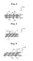
- an anisotropic conductive film 101 shown in Fig. 2 at least one of the ends 1A, 1B of the conductive path 1 protrudes from the principal plane (2a, 2b) of the film substrate 2. More preferably, the ends 1A, 1B of the conductive path 1 protrude from the both principal planes 2a, 2b of the film substrate 2. In other words, the ends of the conductive path 1 more preferably protrude from both the principal plane on the side opposite to an electronic component and the principal plane on the side opposite to a circuit board.
- This permits setting of a lower load necessary for a test when an anisotropic conductive film 101 is used as a test connector. The reason therefore is that the conductive path 1 can more easily contact a terminal of a connection target.
- an anisotropic conductive film 101 can be easily fixed on a circuit board, thus facilitating a test operation itself.
- the protrusion height h1, h2 of the ends 1A, 1B of the conductive path 1 from the both principal planes 2a, 2b of the film substrate 2 is preferably 5 - 40 ⁇ m, more preferably 5 - 30 ⁇ m. It is preferable that the protrusion height of the end of plural conductive paths 1 in one principal plane of the film be the same.
- the protrusion height of the end 1A, 1B of the conductive path 1 from one principal plane 2a and the other principal plane 2b of the film substrate 2 may be the same, as shown in Fig. 2, or different. In the latter case, it is preferable to make the protrusion height from the principal plane opposite to an electronic component (semiconductor element etc.) greater than that from the principal plane opposite to a circuit board.
- the protrusion height of the end of a conductive path from the principal plane opposite to an electronic component is preferably 10 - 40 ⁇ m, more preferably 10 - 30 ⁇ m
- the protrusion height of the end of a conductive path from the principal plane opposite to a circuit board is preferably 5 - 20 ⁇ m, more preferably 5 - 10 ⁇ m, and the difference between the two is preferably 5 - 35 ⁇ m, more preferably 5 - 20 ⁇ m.
- the conductive path 1 When the protrusion height of the end of a conductive path from the principal plane opposite to an electronic component is less than 10 ⁇ m, the conductive path 1 is not easily brought into contact with the terminal of a component whose surface is lower than the surface of the component, and when it exceeds 40 ⁇ m, the protrusion of the end of a conductive path tends to be deformed during a test. In addition, when the protrusion height of the end of a conductive path from the principal plane opposite to a circuit board is less than 5 ⁇ m, the conductive path 1 comes to resist easy contact with a circuit board (circuit) in the repeated use, and when it exceeds 20 ⁇ m, a protrusion part of the conductive path tends to be deformed by the repeated use.
- the centerline of the conductive path 1 penetrates a film substrate 2 while being inclined to form an angle of 5 - 45° with the vertical line of the principal plane of the film substrate 2. More preferably, the end of the conductive path 1 protrudes from the principal plane of the film substrate 2. This has an effect that a narrow pitched terminal contained in an electronic component, whose surface is lower than the surface of the component, and a conductive path of an anisotropic conductive film can be certainly contacted with a small load. This is described somewhat in detail by referring to Figs. 3 and 4.
- the centerline L1 of plural conductive paths 1 is preferably inclined to form an angle of 5 - 45° with the vertical line L2 of the principal plane of the film substrate 2. This has an effect that, when a conductive path 1 contacts a terminal, the conductive path 1 bends and the pressure applied to the terminal decreases more.
- the contact pressure when the conductive path 1 is brought into contact with the terminal of a connection target does not decrease easily, and when it exceeds 45°, the need occurs to adjust (offset) the positions of the end of the conductive path 1 and the terminal of a connection target, which tends to make the handling difficult.
- the angle ⁇ is more preferably 10 - 40°.
- the centerline L1 of the plural conductive paths 1 is inclined to form an angle of 5 - 45° with the vertical line L2 of the principal plane of the film substrate 2, and the ends 1A, 1B of the conductive paths 1 respectively protrude from the both principal planes 2a, 2b of the film substrate 2.
- an electronic component and a circuit board can be functionally testably conducted electrically with a low pressure load even when a terminal is disposed at a narrow pitch of not more than 200 ⁇ m (further, not more than 100 ⁇ m), and a connection target is an electronic component having a surface structure wherein the surface of the terminal is set back from the component surface.
- an electronic component having a surface structure wherein the surface of the terminal is set back from the component surface means an electronic component having a depth from the component surface to the terminal surface is generally about 5 - 20 ⁇ m.
- the protrusion height of the ends 1A, 1B of the conductive path 1 from the both principal planes 2a, 2b of the film substrate 2 is preferably set in the range explained in the above.
- an end of the conductive path 1 protruding from the principal plane of the film substrate 2 is covered by plating.
- the thickness of the coating layer by plating is preferably about 2 - 10 ⁇ m.
- Such coating layer is preferably formed by plating with a metal having high electric conductivity or a corrosion resistant metal.
- Preferable examples thereof include a Ni layer/Au layer by electroless plating. By forming a Ni/Au layer by electroless plating, the aforementioned contact resistance can be reduced.
- the above-mentioned protrusion height of an end of a conductive path from the principal plane of a film substrate when a coating layer by plating is formed on the surface of the end of the conductive path 1 is the height from the principal plane of the film substrate 2 to the surface of the coating layer formed by plating.
- the terminal (electrode) of an electronic component such as a semiconductor element and the like which is the target of functional tests, may have various forms, such as a flat pad, one with a solder bump, one having a periphery of a pad covered with a passivation membrane and the like and a surface set back from the surface of the passivation membrane, in other words, one having a terminal (electrode) surface set back from the surface of a component and the like.
- the circuit board may be a circuit board as a product to mount an electronic component, or a circuit board as a test tool prepared using the same as a model.
- thermoplastic and thermosetting resins such as thermoplastic polyimide resin, epoxy resin, polyetherimide resin, polyamide resin, silicone resin, phenoxy resin, acrylic resin, polycarbodiimide resin, fluorine resin, polyester resin, polyurethane resin and the like; thermoplastic elastomers such as polyurethane thermoplastic elastomer, polyester thermoplastic elastomer, polyamide thermoplastic elastomer and the like; and the like can be mentioned.
- the "insulating resin material” is a concept also including thermoplastic elastomers.
- the thermoplastic elastomer is a preferable material for enhancing the flexibility of an anisotropic conductive film.
- These resins and elastomers may contain various materials such as filler, plasticizer and rubber material.
- the filler include SiO 2 and Al 2 O 3
- examples of the plasticizer include TCP (tricresyl phosphate) and DOP (dioctyl phthalate)
- examples of the rubber material include NBS (acrylonitrile-butadiene rubber), SBS (polystyrene-polybutylene-polystyrene) and the like.
- the anisotropic conductive film of the first embodiment is preferable as a test connector for an electronic component such as a semiconductor element and the like, and the modulus of elasticity of the structure (anisotropic conductive film) as a whole is preferably 10 - 30 MPa at 25 - 40°C, more preferably 10 - 20 MPa.
- the modulus of elasticity is measured using a dynamic viscoelasticity measure apparatus (DMS210, Seiko Instruments Inc.).
- the measurement conditions are an extension mode relative to one direction from among the directions that the surface of the film substrate of the anisotropic conductive film expands at a constant frequency (10 Hz) at a temperature raise rate of 5°C/min and the measurement at -30°C - 250°C.
- the thickness of the sample to be input for measurement is a thickness of the film substrate in the anisotropic conductive film.
- the anisotropic conductive film of this embodiment can be produced by, for example, a method including the following Steps 1 - 3.
- the following production method includes cutting a multilayer structure block comprising a layer of wound wire comprising an insulation wire having a coating layer made from an insulating resin formed on an outer periphery of a conductive wire and an insulating resin film, which are alternately laminated, in a given film thickness.
- a multilayer structure comprising a layer of wound wire comprising an insulation wire and an insulating resin film, which are alternately laminated is placed in a space permitting formation of a decompression or vacuum, and after decompressing or vacuumizing the space, the multilayer structure is heated and pressed to give a block of the multilayer structure.
- an anisotropic conductive film comprising conductive paths aligned regularly can be obtained.
- a block of a multilayer structure is cut into plural blocks, and the plural blocks are integrally connected to give a block having an increased width of a surface where the section of the insulation wire appears, which wide block is then cut to give an anisotropic conductive film.
- an anisotropic conductive film comprising having a relatively large area can be efficiently obtained.
- insulation wire 22 corresponds to the conductive path 1 of an anisotropic conductive film
- insulation wires 22 (conductive wires 22a) aligned in one layer of wound wires 2A corresponds to the rows of conductive paths
- distance (d1) between the centerlines of aligned insulation wires 22 (conductive wires 22a) corresponds to the distance between conductive paths (D1) inside rows of conductive paths (10A - 1, 10A - 2, 10A - 3, 10A - 4 ⁇ ) in an anisotropic conductive film (see Fig. 1).
- the distance between conductive paths between adjacent rows of conductive paths (D2) of an anisotropic conductive film is mainly adjusted by the thickness (d2) of the insulating resin film 21.
- the thickness (d2) of the insulating resin film 21 By adjusting the thickness (d2) of the insulating resin film 21 to not more than 0.8 time (preferably not more than 0.7 time) the distance (d1) between centerlines of the above-mentioned insulation wires 22 (conductive wires 22a), the distance between conductive paths between adjacent rows of conductive paths (D2) can be made smaller than the distance between conductive paths within a row of conductive paths (D1) (see Fig. 1). From the aspect of sufficient insulation between conductive paths, the gap between conductive paths is filled with an insulating resin film.
- thickness (d2) of insulating resin films 21 is preferably not less than 0.1 time the distance (d1) between the centerlines of insulation wires 22 (conductive wires 22a).
- the thickness of the insulating resin coating layer 22b to cover the insulation wire 22 may be such thickness as required for the bond (adhesion) between the insulation wire 22 and the insulating resin film 21, which is generally selected from the range of 1 - 10 ⁇ m.
- Step 2 It is possible to cut out a number of small blocks from the block of multilayer structure 23 in Step 2, stack these small blocks in such a manner that the section of each insulation wire 22 (conductive wire 22a) faces the same direction, heat and press the blocks to integrate them into a block having a greater width, and cut the block having a greater width to give a film having a given thickness with a plane forming an angle with the insulation wire 22 (conductive wire 22a) as a section, whereby an anisotropic conductive film having a relatively large area can be produced. It is preferable to dispose a number of small blocks stuck in a certain direction in a space permitting formation of decompression or vacuum, and after decompressing or vacuumizing the space, heat and press the above-mentioned a number of small blocks.
- the stuck blocks are preferably placed in a heat resistant box having one open plane, and pressed from the side of the open plane.
- the stuck blocks are placed in a bag made of a flexible film, pressed and the inside space is vacuumized, the bag closely adheres to the stuck blocks. As a result, unnecessary gaps inside respective blocks and between blocks can be more effectively removed.
- the box and bag those similar to the box and bag used in Step 2 can be used.
- an anisotropic conductive film obtained through the above-mentioned Steps 1 - 3 can be subjected to the following treatments.
- a method comprising protruding an end of a conductive path by selectively removing the film substrate from the principal plane side can be mentioned.
- wet etching with organic solvent dry etching by plasma etching, argon ion laser, KrF excimer laser and the like are used alone or in combination.
- plasma etching is preferable in view of superior control of etching amount, and of the methods of plasma etching, reactive ion etching is particularly preferable. It is also possible to make protrusion by plating and deposition by precipitating of metal on the end (edge face) of the conductive path from which to protrude.
- the metal When a metal is precipitated, the metal may be the same as or different from the metal constituting the aforementioned conductive path.
- Preferable examples thereof include Ni layer/Au layer by electroless plating. By forming Ni/Au layer by electroless plating, the contact resistance with the terminal of the connection target (electronic component, circuit board etc.) can be advantageously suppressed to a low level.
- anisotropic conductive film of the first embodiment conductive paths are present at relatively high density, and the film has flexibility. Therefore, when functional tests of electronic components such as semiconductor element and the like, wherein terminals (electrodes) are disposed at a narrow pitch, and the terminal surface is set back from the component surface, are performed using this anisotropic conductive film, all terminals (electrodes) of an electronic component and conductive parts of a circuit board can be certainly conducted electrically.
- an electronic component wherein the distance between terminals (electrodes) (width of insulating region between adjacent terminals) is set at a narrow pitch of not more than 200 ⁇ m, further not more than 100 ⁇ m, and moreover, an electronic component wherein the terminals are disposed at a narrow pitch and the surface of the terminal is set at a position of not less than 10 ⁇ m (further not less than 20 ⁇ m) deep from the surface of the component, can be performed at a load of not more than 10 MPa, further not more than 5 MPa.
- the foregoing particularly concerns the usefulness of the anisotropic conductive film of the first embodiment as a test connector.
- the anisotropic conductive film of the first embodiment may be used as a mounting connector.
- this anisotropic conductive film has a structure wherein resin areas are uniformly dispersed, it can be adhered to an electronic component and a circuit board, and an electronic component having terminals disposed at a narrow pitch can be adhered onto a circuit board with relatively high adhesion strength while ensuring fine electric connection.
- the anisotropic conductive film of the first embodiment When used as a test connector, it can be applied not only to the functional tests of electronic components such as a semiconductor element and the like, but also to the functional tests of circuit boards such as a liquid crystal panel, EL (electroluminescence) and the like.
- the test operation can be done with a low pressure load for an article (test subject) having terminals and circuit (wiring) patterns, which is in need of a conduction test, by inserting the anisotropic conductive film of the present invention between the article (test subject) and a circuit board for testing.
- the anisotropic conductive film 100 of the present invention comprises, as the one described in WO98/07216, a plate film substrate 2 made from an insulating material and the conductive paths 1 penetrating the film substrate 2 in the thickness direction while being insulated from each other.
- the above-mentioned film substrate 2 comprises resin and rubber described in detail in the following.
- Fig. 7 schematically shows a test of an electronic component using this anisotropic conductive film.
- the film substrate 2 comprises an acrylic rubber and a naphthalene skeleton epoxy resin crosslinked with a phenol resin. Each resin is described in detail below. As a result of the action of a phenol resin as a crosslinking agent on a naphthalene skeleton epoxy resin, the film substrate 2 shows heat resistance and the presence of an acrylic rubber allows simultaneous expression of flexibility.
- a method to obtain such film substrate 2 may be similar to a known film production method. For example, a method comprising adding a naphthalene skeleton epoxy resin, a phenol resin and an acrylic rubber to a suitable solvent and forming the mixture into a film and the like are mentioned.
- the total weight of a naphthalene skeleton epoxy resin crosslinked with a phenol resin and an acrylic rubber relative to the total weight of the film substrate 2 is preferably not less than 50%, more preferably 70 - 90%.
- materials that may be contained other than the above-mentioned resin and rubber in the film substrate 2 for example, a polyurethane resin, a polyorganosiloxane resin and the like are mentioned, which are free of any particular limitation as long as the characteristics of the present invention are not impaired.
- the amount of the phenol resin to be added to 100 parts by weight of the naphthalene skeleton epoxy resin during the production of film substrate 2 is preferably 30 - 100 parts by weight, more preferably 50 - 70 parts by weight.
- the amount of the acrylic rubber to be added to 100 parts by weight of the naphthalene skeleton epoxy resin during the production of film substrate 2 is preferably 50 - 500 parts by weight, more preferably 70 - 250 parts by weight.
- naphthalene skeleton epoxy resin means a compound having a naphthalene skeleton and not less than two oxirane rings (epoxy groups) in a molecular structure.
- the naphthalene skeleton epoxy resin is generally used concurrently with a hardening agent (compound having active hydrogen, such as phenol, amine etc.) to form a three-dimensional network polymer for use.
- a hardening agent compound having active hydrogen, such as phenol, amine etc.
- the proportion of the naphthalene skeleton in the naphthalene skeleton epoxy resin is not particularly limited, it is preferably 30 wt%, more preferably 40 - 70 wt%, in view of the heat resistance of the obtained film substrate.
- the naphthalene skeleton epoxy resin is a well-known resin and its production method is also well known and free of any particular limitation.
- the "phenol resin” is obtained by condensation of phenol or a derivative thereof with aldehyde.
- phenol or its derivative phenol, cresol and the like can be mentioned.
- aldehyde formaldehyde, acetaldehyde, propionaldehyde, butyl aldehyde and the like can be mentioned.
- the phenol resin is a well-known resin and its production method is also well known and free of any particular limitation.
- the "naphthalene skeleton epoxy resin crosslinked with a phenol resin” is a resin having a two- or three-dimensional network structure, which is formed by bonding of a phenol resin to an oxirane ring (epoxy group) of the aforementioned naphthalene skeleton epoxy resin.
- the "acrylic rubber” is a synthetic rubber mainly comprising an acrylic acid alkyl ester.
- alkyl ester methyl ester, ethyl ester, butyl ester and the like can be mentioned.
- the acrylic rubber is well known and its production method is also well known and free of any particular limitation.
- the film substrate 2 made of the anisotropic conductive film is a plate comprising the aforementioned resin and rubber, whose thickness is not particularly limited. It is preferably about 30 ⁇ m - 1000 ⁇ m, more preferably about 50 ⁇ m - 500 ⁇ m.
- plural conductive paths 1 made from an electrically conductive material are disposed in the film substrate 2 while being insulated from each other and penetrating the film substrate 2 in the thickness direction. Both ends of each conductive path 1 are exposed on the front and back surfaces of the above-mentioned film substrate 2.
- the conductive path 1 penetrates the film substrate 2 in the thickness direction
- an embodiment wherein the conductive path penetrates in the same direction with the thickness direction of the film substrate 2 as shown in Fig. 7 an embodiment wherein the conductive path penetrates with inclination from the aforementioned thickness direction (not shown) and the like, or an embodiment wherein the conductive path 1 penetrates while making a curve rather than linearly in the film substrate 2 (not shown).
- the conductive path 1 is preferably inclined or curved in the film substrate 2.
- each conductive path 1 may be any shape, such as a circle, a polygon and the like. It is preferable that the conductive paths 1 be densely disposed so that about 1 to 3 conductive paths 1 will be in contact with an electrode 20a of the test subject electronic component 20. By making plural conductive paths 1 insulated from each other, the presence or absence of electric conduction of an electrode 20a of an electronic component 20 and a circuit pattern 30a of a circuit board 30 can be independently tested.
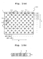
- Fig. 8(a) and Fig. 10 show an arrangement pattern of the conductive paths 1 appearing on one surface of the film substrate 2.
- Fig. 8(b) is a schematic view of a section along X - X of Fig. 8(a).
- the arrangement of the conductive paths 1 may be a square matrix as shown in Fig. 10, a close pack as shown in Fig. 8(a) or other randomly packed state. To deal with a minute electrode, a close pack is preferable.
- the materials of the conductive path 1 known electrically conductive materials can be mentioned. From the aspect of electric property, metal materials such as copper, gold, aluminum, nickel and the like are preferable, and from the aspect of electric conductivity, copper and gold are more preferable. From the aspects of electric conductivity, modulus of elasticity and the like, the conductive path 1 may be formed by plating a metal material in a through hole in the film substrate 2, more preferably, an embodiment wherein a metal wire penetrates a film substrate to make a conductive path.
- conductive metal wires such as copper wire defined in JIS 3 3103 and the like, which are produced to transmit electricity are preferable, since they provide conductive path most superior in electrical property, mechanical property and cost.
- the shape of the section (the section perpendicular to the thickness direction of film substrate 2), size and number of the conductive path 1 can be appropriately determined according to the use of the anisotropic conductive film of the present invention.
- the diameter of the conductive path 1 is preferably 5 - 60 ⁇ m, more preferably 10 - 60 ⁇ m, particularly preferably 10 - 40 ⁇ m.
- the sectional area thereof is preferably about the same area with a circle having the above-mentioned diameter.
- Both ends of the conductive path 1 only need to be exposed on the front and back surfaces of the film substrate 2, and in consideration of fine contact with an electrode 20a of an electronic component 20 and a circuit pattern 30a of a circuit board 30, the both ends of the conductive path 1 preferably protrude from the front and back surfaces of the film substrate (see Fig. 9).
- the degree of protrusion from the front and back surfaces of the film substrate 2 is preferably about 5 - 40 ⁇ m, more preferably about 5 - 30 ⁇ m.
- the protrusion from the conductive path 1 may be metal protrusion formed by plating both ends of the conductive path 1 penetrating the film substrate 2, or the conductive metal wire itself penetrating the film substrate 2 may be extended.
- oxidation is preferably prevented by plating during forming a protrusion.
- the surface of the protrusion may be covered with a metal material having high electric conductivity or a material such as gold, nickel and the like superior in corrosion resistance.
- Fig. 9 is a partial schematic view of the anisotropic conductive film of the second embodiment.
- a layer 3 made from a different material may be formed between the resin material of the film substrate 2 and the conductive path 1.
- the layer 3 may be superimposed in many layers, and the material may be selected according to use and required properties such as insulation property, electric conductivity and the like.
- a material to be used for layer 3 winding the conductive path polyimide resin, polyamide resin, polyester resin, polyurethane resin and the like can be mentioned.
- the modulus of elasticity of the anisotropic conductive film as a whole of this embodiment at 20°C - 150°C is preferably 1 - 100 MPa, more preferably 10 - 20 MPa.
- the modulus of elasticity is not less than 1 MPa, a test subject does not adhere too easily to an electronic component 20 and the electronic component 20 can be easily recovered after the test.
- the modulus of elasticity is not more than 100 MPa, since swelling of substrate, warp of chip and the like can be easily absorbed by application of a suitable contact load to be mentioned later, defective electric conduction resulting from damage and the like of the conductive path 1 can be reduced.
- the modulus of elasticity of the anisotropic conductive film as a whole means the modulus of elasticity of an anisotropic conductive film as a finished product including the film substrate 2 and the conductive path 1, and can be measured by the following tensile test.
- the thickness of the anisotropic conductive film of the present invention is preferably 30 - 1000 ⁇ m, more preferably 50 - 500 ⁇ m.
- the thickness of an anisotropic conductive film means, of the distances between two points of the anisotropic conductive film, the maximum length in the direction perpendicular to the plane expanding direction of the film substrate 2.
- the thickness of an anisotropic conductive film is the same as the thickness of the film substrate 2 and when the conductive path 1 protrudes from the film substrate 2, the thickness of the anisotropic conductive film is generally the distance between both ends of the conductive paths 1 (length T in Fig. 9).
- the anisotropic conductive film of the second embodiment can reduce staining of a metal electrode due to adhesion of low molecular weight components, which occurs when used for the test of an electronic component and the like at 20°C - 150°C.
- a method for obtaining a structure wherein the conductive path 1 penetrates the film substrate 2 is not particularly limited.
- a method comprising fixing a number of insulated conductive wires in a densely packed state to prevent separation from each other, and cutting in a desired film thickness with a plane forming an angle with each insulated electrode as a cutting plane can be mentioned.
- a method comprising the following steps of (1) - (7), or (1) - (5) and (7) can be mentioned.
- the test subject is an electronic component having at least one electrode.
- the "electronic component” is meant a component that expresses function by electric conduction and includes semiconductor element, liquid crystal panel, high frequency component and the like.
- Application of the test method of the present invention to electronic equipment and semiconductor device incorporating an electronic component falls under the application of the test method to electronic components.
- This test method is characterized by, as shown in Fig. 7, inserting an anisotropic conductive film 100 of the second embodiment between an electronic component 20 and a circuit board 30 and, while applying a given load, electrically conducting an electronic component 20.
- the anisotropic conductive film 100 deforms to absorb them, whereby an electrode 20a of an electronic component and a corresponding circuit pattern 30a on the circuit board 30 are suitably brought into contact preferably with a minimum load.
- circuit board may be a circuit board as a product to mount an electronic component 20 or a circuit board produced as a test tool using it as a model.
- an electrode 20a of the above-mentioned electronic component 20 and the conductive path 1 of the anisotropic conductive film are brought into contact with each other. It is preferable that the conductive paths 1 be densely disposed so that about 1 to 3 conductive paths 1 will be in contact with an electrode 20a of a test subject electronic component 20.
- a load is applied in the direction to press an anisotropic conductive film 100 and an electronic component 20, while inserting, as mentioned above, the anisotropic conductive film 100 between the electronic component 20 and a circuit board 30.
- a load in such direction is realized by, for example, as shown in Fig. 1, fixing the circuit board 30 on a base (table) and pressing from the electronic component 20 side.
- the contact load then is preferably 50 g/mm 2 - 5000 g/mm 2 per one electrode of an electronic component, and when a circuit board 30 of the test subject is flat, it is particularly preferably 100 g/mm 2 - 3000 g/mm 2 . This contact load hardly give damage to deform an electrode 20a of an electronic component 20, and is in the range decreasing the contact resistance.
- the "contact load per one electrode” means a value obtained by dividing the total load applied to an electronic component 20 by the number of electrodes 20a that have come into contact therewith.
- the electrode 20a is an electrode contained in an electronic component 20, a test subject.
- the total load applied on the electronic component 20 can be controlled by, for example, setting of a flip chip bonder.
- the load applied while sandwiching an anisotropic conductive film 100 between an electronic component 20 and a circuit board 30 as mentioned above is preferably a load that decreases the thickness of the anisotropic conductive film 100 by 5 ⁇ m - 150 ⁇ m.
- the amount of dislocation (amount of decreased thickness) of the anisotropic conductive film during the test can be directly measured by a micro compression testing machine (Shimadzu Corporation, MCT - W).
- test subject of an electronic component 20 is electrically conducted while applying a load to test the electronic component 20.
- the test is not particularly limited if it requires electric conduction to an electronic component 20 and may be, for example, confirmation of electric conduction or measurement of contact resistance in electrode 20a.
- An aluminum cylindrical core having a diameter of 320 mm and a length of 270 mm is set on a horizontal type regular winding machine (HPW - 02, Nittoku Engineering Co., Ltd.), on which a 50 ⁇ m-thick fluorocarbon resin film as a slip film and a film consisting of a 50 ⁇ m-thick thermoplastic polyurethane elastomer having a rubber hardness of 75 degrees (Esmer URS, Nihon Matai Co., Ltd., softening temperature 60°C) were wound, and a heat-resistant polyurethane coated wire (copper wire (diameter 25 ⁇ m) coated with heat resistant polyurethane in 2 ⁇ m thickness) having a diameter of 29 ⁇ m was wound 250 mm at a winding intervals (pitch) of 100 ⁇ m.
- HPW - 02 Nittoku Engineering Co., Ltd.
- thermoplastic polyurethane elastomer film similar to the above, winding of heat resistant polyurethane coated wire was further repeated 54 times, during which the odd-numbered layers of wound wires and even-numbered layers of wound wires from the core side were displaced such that the start position of the insulation wire winding was moved by 50 ⁇ m in the longitudinal direction of the aluminum cylindrical core.
- a 50 ⁇ m-thick fluorocarbon resin film was wound as a slip film on the outer periphery of a multilayer structure in which the thus-obtained thermoplastic polyurethane elastomer film and a layer of wound wire comprising heat resistant polyurethane coated copper wire are alternately laminated, and a 1 mm thick aluminum plate was set as a support plate along the cylindrical shape of the core.
- a bag permitting formation of a vacuum space was prepared from a 80 ⁇ m-thick heat resistant nylon film (1000 mm ⁇ 1530 mm, WL 8400-003-60-1000-SHT9, Airtec Co., Ltd., softening temperature: 220°C) and a seal tape GS213 (Airtec Co., Ltd.), and a multilayer structure, a core and a support plate in integration were placed in this bag.
- the film space was hermetically sealed and sucked with a vacuum hose (connected to a vacuum pump) to vacuumize the film space. While maintaining the vacuum, the bag containing the core, the multilayer structure and the support plate was placed in a heat press treatable autoclave (Ashida Co., Ltd.).
- the inside of the tube was heated to make the temperature of the core 155°C (temperature inside the tube: 200°C), along with which the tube was pressed with a nitrogen gas to make the pressure inside the tube 10 kgf/cm 2 . After the core temperature and the pressure in the tube reached the objective levels, the tube was cooled until the temperature inside the tube reached 60°C and the pressure was released.
- the aforementioned roll-like block was cut into plural rectangular blocks of 120 mm in length ⁇ 62 mm in width ⁇ 3.2 mm in thickness and after laminating these, the laminated blocks were put in an aluminum box having a size where the gap between the block and the inner wall of the box was 1.5 mm.
- An aluminum plate 120 mm ⁇ 62 mm was placed into the above-mentioned aluminum box from an opening on the upper surface of the box and on the uppermost surface of the aforementioned laminate.
- the aluminum box containing the laminate was placed in the bag made of a heat resistant nylon film, which was used in the above.
- the bag was placed in an autoclave.
- the aluminum box was heated to a temperature of 175°C (temperature inside the tube: 200°C), along with which the tube was pressed with a nitrogen gas, such that the pressure inside thereof became 15 kgf/cm 2 .
- the inside of the tube was cooled to 60°C, and the pressure was released.
- a large size block in which the laminated blocks were integrated was taken out of the box and the block was cut using a wire saw (F-600, Yasunaga Corporation) so that the plane orthogonal to (the centerline of) the conductive wire inside becomes a section, and a film 65 mm in length ⁇ 120 mm in width ⁇ 100 ⁇ m in thickness was cut out.
- the arrangement pattern of the conductive paths in the anisotropic conductive film prepared as above was observed using a stereo microscope, and the intervals (distances) corresponding to D1 - D4 in Fig. 1 (a) were measured by a microscope.
- D1 was 100 ⁇ m
- D2 was 70 ⁇ m
- D3 was 107 ⁇ m
- D4 was 70 ⁇ m, respectively.
- the modulus of elasticity of the entire film at 25 - 40°C was 17 - 20 MPa.
- the sections (both sides) of the anisotropic conductive film prepared in Example 1 were treated using CF 4 as etching gas at a power of 2000 W and a gas flow of 0.5 L/min for 30 min to prepare an anisotropic conductive film in which the end of the conductive path is protruded from both principal planes of the film substrate for 15 ⁇ m.
- the modulus of elasticity of the anisotropic conductive film at 25 - 40°C was 16 - 18 MPa.
- one side of the section of the anisotropic conductive film prepared in Example 1 was treated using CF 4 as etching gas at a power of 2000 W and a gas flow of 0.5 L/min for 30 min, so that the end of the conductive path was protruded from the principal plane of the film substrate (principal plane facing the circuit board) for 15 ⁇ m, and the other side of the section was treated using CF 4 as etching gas at a power of 2000 W and a gas flow of 0.5 L/min for 60 min, so that the end of the conductive path was protruded from the principal plane of the film substrate (principal plane facing the electronic component) for 30 ⁇ m, whereby an anisotropic conductive film having a different protrusion amount at the end of the conductive path from each principal plane of the film was prepared.
- the modulus of elasticity of the anisotropic conductive film at 25 - 40°C was 15 - 17 MPa.
- the block prepared in the above-mentioned Example 1 was cut using a wire saw (F - 600, Yasunaga Corporation), so that the plane crossing at an angle of 75° to (the centerline of) the conductive wire inside becomes a section, and a film of 65 mm in length ⁇ 120 mm in width ⁇ 100 ⁇ m in thickness in which the centerlines of the plural conductive paths form an angle of 15° to the vertical line of the principal plane of the film substrate was cut out.
- a wire saw F - 600, Yasunaga Corporation
- the principal plane of the anisotropic conductive film prepared as above was observed by a stereomicroscope, and the section of each conductive path (the plane exposed from the principal plane of the film substrate) was an ellipse. With the center thereof being a centerline, the distances between the centerlines corresponding to D1, D2, D3 and D4 in Fig. 1(a) were measured by a microscope to be 100 ⁇ m, 70 ⁇ m, 107 ⁇ m and 70 ⁇ m, respectively.
- the sections (both sides) of the anisotropic conductive film prepared as above were treated using CF 4 as etching gas at a power of 2000 W and a gas flow of 0.5 L/min for 30 min to prepare an anisotropic conductive film in which the end of the conductive path is protruded from both principal planes of the film substrate for 15 ⁇ m.
- the modulus of elasticity of the anisotropic conductive film at 25 - 40°C was 16 - 18 MPa.
- connection test (electric conduction test) between the electronic component and the circuit board was carried out.
- An anisotropic conductive film is disposed between the electronic component for evaluation and the circuit board for evaluation and a contact load is applied from the electronic component side to observe if the electric conduction between all the terminals (electrode) of the electronic component and the circuit board can be achieved (electric conduction at all points).
- the contact load required for the all point electric conduction was 2.5 MPa.
- connection test (electric conduction test) between the electronic component and circuit board was carried out.
- An anisotropic conductive film is disposed between the electronic component for evaluation and the circuit board for evaluation and a contact load is applied from the electronic component side to observe if the electric conduction between all the terminals (electrode) of the electronic component and the circuit board can be achieved (electric conduction at all points).
- the contact load required for the all point electric conduction was 10 MPa when the anisotropic conductive film of Example 2 was used, 8 MPa when the anisotropic conductive film of Example 3 was used and 5 MPa when the anisotropic conductive film of Example 4 was used.
- Anisotropic conductive films (Example 5, Comparative Examples 1, 2) were produced according to the steps (1) - (7) above.
- the materials of the film substrate of each anisotropic conductive film are as described below.
- naphthalene type epoxy resin epoxy equivalent amount 270
- cresol novolac type epoxy resin hydroxyl group equivalent amount 174
- acrylic rubber epoxy monomer copolymerization crosslinking type 170 (parts by weight)
- polyether type polyurethane rubber (Nisshinbo Industries, Inc., MF-50T-MX)
- silicone rubber (a commercially available compound containing siloxane as a main component to which a vulcanizing agent is added)
- the following anisotropic conductive film was produced using a film substrate made of the above-mentioned materials.
- the electronic component (semiconductor element) for the test is as follows.
- circuit board for evaluation Details of circuit board for evaluation are as follows.
- An anisotropic conductive film was disposed between the above-mentioned electronic component and circuit board. By applying a load of 200 g/m 2 per electrode, electric conduction was carried out to measure and observe the amount of displacement, bump deformation and adhesion to the substrate. The measurement and test were performed for each film at 20°C and 150°C. The results are shown in Table 1.
- the "amount of silicone component adhered to test subject” means a value obtained by quantifying the silicone component left on the contact face by a SEM - EPMA method after pressing the anisotropic conductive film on copper foil.
- the "electric connection” was evaluated as “OK” when electric conduction was confirmed by a compression testing machine and "NG” when not confirmed.
- the film of Comparative Example 1 (using polyurethane rubber) can be used at room temperature (20°C) but is not a superior anisotropic conductive film in that adhesion to the circuit board is observed at 150°C.
- Comparative Example 2 using silicone rubber, the low molecular weight component of silicone adheres (be transferred) to the test subject, and therefore the film is not good as an anisotropic conductive film for test.
- the anisotropic conductive films of Examples have high heat resistance, no weld-adhesion at high temperatures and are free of contamination of test subject due to low molecular weight component, and are a superior anisotropic conductive film which can be used in a wide temperature range.
Landscapes
- Physics & Mathematics (AREA)
- General Physics & Mathematics (AREA)
- Engineering & Computer Science (AREA)
- Manufacturing & Machinery (AREA)
- Non-Insulated Conductors (AREA)
- Manufacturing Of Electrical Connectors (AREA)
- Manufacturing Of Electric Cables (AREA)
- Laminated Bodies (AREA)
Abstract
Description
the insulating resin film used in
and wherein in
- measurement apparatus TA Instruments Japan, viscoelasticity measure apparatus RSA - II,
-
test piece 100 µm × 5mm × 22.5 mm, - measurement conditions The properties at
frequency 10 Hz,temperature 20°C, 150°C in one of the plane expanding directions of a test piece are measured under an extension mode.
- To reduce the amount of an acrylic rubber to be added.
- To use a material having a small proportion of a naphthalene skeleton in a naphthalene skeleton epoxy resin.
- To use an epoxy resin and a phenol resin having plural functional groups in one molecule.
| naphthalene type epoxy resin (epoxy equivalent amount 270) | 100 (parts by weight) |
| cresol novolac type epoxy resin (hydroxyl group equivalent amount 174) | 65 (parts by weight) |
| acrylic rubber (epoxy monomer copolymerization crosslinking type) | 170 (parts by weight) |
- film substrate thickness: 200 µm
- protrusion length of conductive path from both sides of film substrate: 20 µm
- thickness of gold plating on both ends of conductive path: 0.2 µm
- entire thickness of anisotropic conductive film: 240 µm
- diameter of conductive path: 25 µm
- distance (pitch) between centerlines of adjacent
conductive paths 100 µm
- chip size: 10 mm × 10 mm (thickness :500 µm)
- kind of electrode: Au stud bump
- bump diameter of electrode: 70 µm
- bump height: 70 µm
- number of electrodes: 156
- pitch between centers of electrodes: 200 µm
- glass epoxy substrate : FR - 4
- thickness including the thickness of circuit pattern: 1 mm
- ratio of circuit width and interval width of circuit pattern: 100 µm/100 µm
| Example 5 | Comp. Ex. 1 | Comp. Ex. 2 | ||||
| Measurement and test temperature (°C) | 20 | 150 | 20 | 150 | 20 | 150 |
| elastic modulus (MPa) | 100 | 20 | 15 | <0.1 | 90 | 80 |
| decrease of thickness (µm) when load was applied | 8 | 12 | 10 | 60 | 10 | 10 |
| Amount of silicone component (mol%) adhered to test | 0 | 0 | 0 | 0 | 10 | 120 |
| electric connection | OK | OK | OK | NG | OK | OK |
| adhesion to the substrate | no | no | no | yes | no | no |
| evaluation | ○ | ○ | ○ | × | × | × |
Claims (15)
- An anisotropic conductive film for testing an electronic component, which comprises a film substrate comprising an insulating resin and plural conductive paths insulated from each other and penetrating the film substrate in the thickness direction.
- The anisotropic conductive film of claim 1, wherein the plural conductive paths are disposed in a houndstooth check pattern and the distance between conductive paths between adjacent rows of conductive paths is smaller than the distance between conductive paths within a row of conductive paths.
- The anisotropic conductive film of claim 2, wherein the distance between conductive paths between adjacent rows of conductive paths is smaller than the distance between conductive paths within a row of conductive paths both in one direction where plural rows of conductive paths in the principal plane of the film are arranged in parallel to each other, and the other direction perpendicular to said direction.
- The anisotropic conductive film of claim 2 or 3, wherein the conductive path has an outer diameter of 10 - 60 µm, the distance between conductive paths within a row of conductive paths is 30 - 200 µm, and the distance between conductive paths between adjacent rows of conductive paths is not more than 4/5 of the distance between conductive paths within a row of conductive paths.
- The anisotropic conductive film of any of claims 2 to 4, wherein the centerline of the plural conductive paths is inclined to form an angle of 5 - 45° with the vertical line of the principal plane of the film substrate.
- The anisotropic conductive film of any of claims 2 to 5, wherein at least one end of the conductive path protrudes from the principal plane of a film substrate.
- The anisotropic conductive film of claim 6, wherein both ends of the conductive path protrude from the principal planes of the film substrate.
- The anisotropic conductive film of claim 1, wherein the insulating resin comprises a naphthalene skeleton epoxy resin crosslinked with a phenol resin and an acrylic rubber, and both ends of the plural conductive paths are exposed on both the front and the back surfaces of the film substrate.
- The anisotropic conductive film of claim 8, wherein the film as a whole has a modulus of elasticity of 1 MPa - 100 MPa at 20°C - 150°C, and the film has a thickness of 30 µm - 1000 µm.
- The anisotropic conductive film of claim 8 or 9, wherein both ends of the conductive paths protrude from the front and the back surfaces of the film substrate, a part of the conductive path, which penetrates the film substrate, is a conductive metal wire having a diameter of 10 µm - 60 µm, the protrusion of the conductive path from the film substrate is made of the conductive metal wire itself extending from the film substrate, or a metal protrusion formed by plating the end of the above conductive metal wire.
- A production method of the anisotropic conductive film of claim 1, which comprises the following steps:whereinStep 1: one sheet of an insulating resin film is wound roll-like around a core, an insulation wire comprising a conductive wire and a coating layer made of an insulating resin, which is formed on the outer periphery of the conductive wire, is wound around the outer periphery of the roll-like insulating resin film at a constant pitch like a coil, thereby to form a layer of wound wire, and this process is repeated to give a multilayer structure wherein the insulating resin film and the layer of wound wire of are alternately laminated,Step 2: the multilayer structure is heated and pressed to melt at least the insulating resin film in the multilayer structure to give a block of the multilayer structure, and,Step 3: the blocked multilayer structure is cut in a given film thickness along a plane forming an angle with a conductive wire therein as a section,
the insulating resin film used in Step 1 has a thickness of not more than 0.8 times the distance (pitch) between the centerlines of the adjacent insulation wires in the layer of wound wire to be formed,
and wherein
in Step 1, the winding position of the insulation wire is moved to the longitudinal direction of the core during formation of odd-numbered layers of wound wire and even-numbered layers of wound wire as counted from the core side, such that a middle point between the centerlines of the adjacent insulation wires in the odd-numbered layers of wound wire and the centerline of the insulation wires in the even-numbered layers of wound wire, both as counted from the core side, are aligned on the same virtual straight line. - The production method of claim 11, wherein, in Step 2, the multilayer structure obtained in Step 1 is disposed in a space that can be decompressed or vacuumized, and the multilayer structure is heated and pressed to give a block after decompressing or vacuumizing the aforementioned space.
- The production method of claim 11 or 12, wherein the block of multilayer structure obtained in Step 2 is cut into plural blocks, the plural blocks are integrally connected to give a block having an enlarged section of the insulation wire, and Step 3 is applied to the block having a greater width.
- A method of testing an electronic component, which comprises disposing the anisotropic conductive film of any of claims 8 to 10 between an electronic component comprising at least one electrode and a circuit board, such that an electrode of the electronic component and a conductive path of the anisotropic conductive film are in contact with each other, and the electronic component is electrically conducted while applying a contact load of 50 g/mm2 - 5000 g/mm2 per one electrode of the electronic component in the direction to press the anisotropic conductive film and the electronic component.
- The test method of claim 14, wherein application of the load compresses the anisotropic conductive film and the thickness of the film decreases by 5 µm - 150 µm.
Applications Claiming Priority (4)
| Application Number | Priority Date | Filing Date | Title |
|---|---|---|---|
| JP2003317453A JP2005085634A (en) | 2003-09-09 | 2003-09-09 | Anisotropic conductive film and manufacturing method thereof |
| JP2003317453 | 2003-09-09 | ||
| JP2003326810A JP4256237B2 (en) | 2003-09-18 | 2003-09-18 | Anisotropic conductive film for electronic component inspection and electronic component inspection method using the same |
| JP2003326810 | 2003-09-18 |
Publications (3)
| Publication Number | Publication Date |
|---|---|
| EP1515399A2 true EP1515399A2 (en) | 2005-03-16 |
| EP1515399A3 EP1515399A3 (en) | 2006-08-02 |
| EP1515399B1 EP1515399B1 (en) | 2008-12-31 |
Family
ID=34138016
Family Applications (1)
| Application Number | Title | Priority Date | Filing Date |
|---|---|---|---|
| EP04021330A Expired - Lifetime EP1515399B1 (en) | 2003-09-09 | 2004-09-08 | Anisotropic conductive film, production method thereof and method of use thereof |
Country Status (7)
| Country | Link |
|---|---|
| US (1) | US7156669B2 (en) |
| EP (1) | EP1515399B1 (en) |
| KR (1) | KR20050026683A (en) |
| AT (1) | ATE419661T1 (en) |
| DE (1) | DE602004018720D1 (en) |
| SG (1) | SG110194A1 (en) |
| TW (1) | TW200515644A (en) |
Cited By (2)
| Publication number | Priority date | Publication date | Assignee | Title |
|---|---|---|---|---|
| EP2221926A4 (en) * | 2007-12-10 | 2016-03-30 | Fujifilm Corp | ANISOTROPIC CONDUCTIVE JUNCTION KIT |
| TWI742642B (en) * | 2020-05-05 | 2021-10-11 | 泰可廣科技股份有限公司 | Electrical connection assembly with oblique guide wire type conductive film |
Families Citing this family (43)
| Publication number | Priority date | Publication date | Assignee | Title |
|---|---|---|---|---|
| US8518304B1 (en) | 2003-03-31 | 2013-08-27 | The Research Foundation Of State University Of New York | Nano-structure enhancements for anisotropic conductive material and thermal interposers |
| US7133991B2 (en) * | 2003-08-20 | 2006-11-07 | Micron Technology, Inc. | Method and system for capturing and bypassing memory transactions in a hub-based memory system |
| TWI255466B (en) * | 2004-10-08 | 2006-05-21 | Ind Tech Res Inst | Polymer-matrix conductive film and method for fabricating the same |
| NL1027450C2 (en) * | 2004-11-09 | 2006-05-10 | Shin Etsu Polymer Europ B V | Interconnection connector, frame comprising such a connector, electrical measuring and testing device and contacting method with the aid of such a connector. |
| JP2006330130A (en) * | 2005-05-24 | 2006-12-07 | Mitsubishi Electric Corp | Liquid crystal display device and manufacturing method thereof |
| US7235978B2 (en) * | 2005-09-07 | 2007-06-26 | Matsushita Electric Industrial Co., Ltd. | Device for measuring impedance of electronic component |
| KR100721587B1 (en) * | 2006-03-09 | 2007-05-23 | 주식회사 아이에스시테크놀러지 | Contactor for inspection of electronic parts |
| US7331797B1 (en) * | 2006-07-26 | 2008-02-19 | Lotes Co., Ltd. | Electrical connector and a manufacturing method thereof |
| EP1976007B1 (en) | 2007-03-27 | 2017-11-29 | Fujifilm Corporation | Method of manufacture of anisotropically conductive member |
| JP5104034B2 (en) * | 2007-05-23 | 2012-12-19 | 日立化成工業株式会社 | Anisotropic conductive connection film and reel body |
| KR100920228B1 (en) * | 2007-11-21 | 2009-10-05 | 삼성전기주식회사 | Probe Card with Thermoplastics |
| JP2009132974A (en) * | 2007-11-30 | 2009-06-18 | Fujifilm Corp | Fine structure |
| JP2009283431A (en) * | 2007-12-27 | 2009-12-03 | Fujifilm Corp | Microstructural body and method of manufacturing the same |
| TWI377624B (en) * | 2008-05-13 | 2012-11-21 | Ind Tech Res Inst | Conducting film structure, fabrication method thereof, and conducting film type probe device for ic |
| JP5143045B2 (en) * | 2008-07-09 | 2013-02-13 | 富士フイルム株式会社 | Fine structure and manufacturing method thereof |
| TWI399812B (en) * | 2008-12-29 | 2013-06-21 | Ind Tech Res Inst | Conducting film structure, fabrication method thereof, and conducting film type probe device for ic |
| JP5164878B2 (en) | 2009-02-17 | 2013-03-21 | 富士フイルム株式会社 | Anisotropic conductive member and manufacturing method thereof |
| WO2010101125A1 (en) * | 2009-03-05 | 2010-09-10 | ポリマテック株式会社 | Elastic connector and method of manufacturing same and conductive connector |
| US8872038B2 (en) * | 2009-09-02 | 2014-10-28 | Polymatech Co., Ltd. | Anisotropic conductor, method of producing the same, and anisotropic conductor-arranged sheet |
| KR101127449B1 (en) * | 2009-10-07 | 2012-03-26 | 이성규 | Method for producing an anisotropic conductive film and anisotropic conductive film produced by the same |
| JP2011090865A (en) * | 2009-10-22 | 2011-05-06 | Shinko Electric Ind Co Ltd | Conductive film and manufacturing method therefor, and semiconductor device and manufacturing method therefor |
| US8507804B2 (en) * | 2010-02-22 | 2013-08-13 | Tyco Electronics Corporation | Electrical connector with solder columns |
| US8574964B2 (en) * | 2010-04-14 | 2013-11-05 | Stats Chippac, Ltd. | Semiconductor device and method of forming electrical interconnection between semiconductor die and substrate with continuous body of solder tape |
| WO2015111542A1 (en) * | 2014-01-27 | 2015-07-30 | 富士フイルム株式会社 | Microstructure, multilayer wiring board, semiconductor package and microstructure manufacturing method |
| JP2015207433A (en) * | 2014-04-18 | 2015-11-19 | 矢崎総業株式会社 | Conductive elastic member and connector |
| WO2016006660A1 (en) * | 2014-07-11 | 2016-01-14 | 富士フイルム株式会社 | Anisotropic conductive member and multilayer wiring substrate |
| CN105305126A (en) * | 2015-11-20 | 2016-02-03 | 华为技术有限公司 | Electric connector and communication equipment |
| US10330874B2 (en) * | 2016-02-02 | 2019-06-25 | Georgia Tech Research Corporation | Mixed-signal substrate with integrated through-substrate vias |
| WO2017191772A1 (en) * | 2016-05-05 | 2017-11-09 | デクセリアルズ株式会社 | Filler alignment film |
| JP2018067483A (en) * | 2016-10-20 | 2018-04-26 | ヤマハ株式会社 | Anisotropic conductive sheet, electric inspection head, electric inspection device, and method for manufacturing anisotropic conductive sheet |
| US11637406B2 (en) * | 2017-05-18 | 2023-04-25 | Shin-Etsu Polymer Co., Ltd. | Electrical connector and method for producing same |
| CN107492724B (en) * | 2017-07-05 | 2019-11-05 | 华为技术有限公司 | A kind of connector and preparation method thereof, communication equipment |
| KR20190023028A (en) * | 2017-08-25 | 2019-03-07 | 삼성디스플레이 주식회사 | Connecting member and display device having the same and manufacturing of display device |
| CN108447589B (en) * | 2018-04-18 | 2024-05-24 | 江苏金奕达铜业股份有限公司 | Can splice copper bar |
| KR102280651B1 (en) * | 2018-12-26 | 2021-07-23 | 주식회사 아이에스시 | Connector for electrical connection and manufacturing method thereof |
| KR102110150B1 (en) * | 2019-01-08 | 2020-06-08 | (주)티에스이 | Protective member for conduction part of data signal transmission connector, manufacturing method for the same, data signal transmission connector having the protective member and manufacturing method for the data signal transmission connector |
| TWI672711B (en) | 2019-01-10 | 2019-09-21 | 健策精密工業股份有限公司 | Insulated metal substrate and manufacturing method thereof |
| US11139262B2 (en) | 2019-02-07 | 2021-10-05 | Micron Technology, Inc. | Use of pre-channeled materials for anisotropic conductors |
| CN109796903B (en) * | 2019-03-08 | 2024-06-21 | 深圳市润沃自动化工程有限公司 | Anisotropic conductive adhesive structure and production method thereof |
| CN110996494B (en) * | 2019-12-19 | 2024-06-04 | 北京比特大陆科技有限公司 | Circuit board and server with same |
| KR102466241B1 (en) * | 2020-05-27 | 2022-11-14 | 주식회사 아이에스시 | Connector for electrical connection |
| KR20220166865A (en) * | 2020-05-29 | 2022-12-19 | 미쓰이 가가쿠 가부시키가이샤 | Anisotropic conductive sheet, manufacturing method of anisotropic conductive sheet, electrical inspection device and electrical inspection method |
| CN117476584B (en) * | 2023-09-28 | 2026-04-28 | 泉州市三安集成电路有限公司 | Interconnect components and electronic device interconnect assemblies |
Family Cites Families (25)
| Publication number | Priority date | Publication date | Assignee | Title |
|---|---|---|---|---|
| US3541222A (en) * | 1969-01-13 | 1970-11-17 | Bunker Ramo | Connector screen for interconnecting adjacent surfaces of laminar circuits and method of making |
| US3620873A (en) * | 1969-03-26 | 1971-11-16 | Ercon Inc | Making metal-plastic gasket materials |
| US3971610A (en) * | 1974-05-10 | 1976-07-27 | Technical Wire Products, Inc. | Conductive elastomeric contacts and connectors |
| US4008300A (en) * | 1974-10-15 | 1977-02-15 | A & P Products Incorporated | Multi-conductor element and method of making same |
| US4209481A (en) * | 1976-04-19 | 1980-06-24 | Toray Industries, Inc. | Process for producing an anisotropically electroconductive sheet |
| JPS5555985U (en) * | 1978-10-12 | 1980-04-16 | ||
| US4249302A (en) * | 1978-12-28 | 1981-02-10 | Ncr Corporation | Multilayer printed circuit board |
| US4988306A (en) * | 1989-05-16 | 1991-01-29 | Labinal Components And Systems, Inc. | Low-loss electrical interconnects |
| US4820376A (en) * | 1987-11-05 | 1989-04-11 | American Telephone And Telegraph Company At&T Bell Laboratories | Fabrication of CPI layers |
| US5071359A (en) * | 1990-04-27 | 1991-12-10 | Rogers Corporation | Array connector |
| US5101553A (en) * | 1991-04-29 | 1992-04-07 | Microelectronics And Computer Technology Corporation | Method of making a metal-on-elastomer pressure contact connector |
| EP0560072A3 (en) * | 1992-03-13 | 1993-10-06 | Nitto Denko Corporation | Anisotropic electrically conductive adhesive film and connection structure using the same |
| US5259110A (en) * | 1992-04-03 | 1993-11-09 | International Business Machines Corporation | Method for forming a multilayer microelectronic wiring module |
| US5515604A (en) * | 1992-10-07 | 1996-05-14 | Fujitsu Limited | Methods for making high-density/long-via laminated connectors |
| JP2500462B2 (en) * | 1993-07-22 | 1996-05-29 | 日本電気株式会社 | Inspection connector and manufacturing method thereof |
| EP0645950B1 (en) * | 1993-09-21 | 1998-09-02 | Matsushita Electric Industrial Co., Ltd. | Connecting member of a circuit substrate and method of manufacturing multilayer circuit substrates by using the same |
| JP3400051B2 (en) * | 1993-11-10 | 2003-04-28 | ザ ウィタカー コーポレーション | Anisotropic conductive film, method of manufacturing the same, and connector using the same |
| US5509815A (en) * | 1994-06-08 | 1996-04-23 | At&T Corp. | Solder medium for circuit interconnection |
| US5447264A (en) * | 1994-07-01 | 1995-09-05 | Mcnc | Recessed via apparatus for testing, burn-in, and/or programming of integrated circuit chips, and for placing solder bumps thereon |
| US5497938A (en) * | 1994-09-01 | 1996-03-12 | Intel Corporation | Tape with solder forms and methods for transferring solder to chip assemblies |
| US6245175B1 (en) | 1996-08-08 | 2001-06-12 | Nitto Denko Corporation | Anisotropic conductive film and production method thereof |
| JPH10308565A (en) * | 1997-05-02 | 1998-11-17 | Shinko Electric Ind Co Ltd | Wiring board |
| US6059579A (en) * | 1997-09-24 | 2000-05-09 | International Business Machines Corporation | Semiconductor structure interconnector and assembly |
| JP2002042921A (en) | 2000-04-18 | 2002-02-08 | Nitto Denko Corp | Method for producing anisotropic conductive film and anisotropic conductive film |
| US6465084B1 (en) * | 2001-04-12 | 2002-10-15 | International Business Machines Corporation | Method and structure for producing Z-axis interconnection assembly of printed wiring board elements |
-
2004
- 2004-09-08 DE DE602004018720T patent/DE602004018720D1/en not_active Expired - Lifetime
- 2004-09-08 EP EP04021330A patent/EP1515399B1/en not_active Expired - Lifetime
- 2004-09-08 AT AT04021330T patent/ATE419661T1/en not_active IP Right Cessation
- 2004-09-09 SG SG200405710A patent/SG110194A1/en unknown
- 2004-09-09 TW TW093127253A patent/TW200515644A/en unknown
- 2004-09-09 US US10/936,946 patent/US7156669B2/en not_active Expired - Fee Related
- 2004-09-09 KR KR1020040072303A patent/KR20050026683A/en not_active Ceased
Cited By (2)
| Publication number | Priority date | Publication date | Assignee | Title |
|---|---|---|---|---|
| EP2221926A4 (en) * | 2007-12-10 | 2016-03-30 | Fujifilm Corp | ANISOTROPIC CONDUCTIVE JUNCTION KIT |
| TWI742642B (en) * | 2020-05-05 | 2021-10-11 | 泰可廣科技股份有限公司 | Electrical connection assembly with oblique guide wire type conductive film |
Also Published As
| Publication number | Publication date |
|---|---|
| US7156669B2 (en) | 2007-01-02 |
| EP1515399A3 (en) | 2006-08-02 |
| SG110194A1 (en) | 2005-04-28 |
| DE602004018720D1 (en) | 2009-02-12 |
| EP1515399B1 (en) | 2008-12-31 |
| KR20050026683A (en) | 2005-03-15 |
| US20050077542A1 (en) | 2005-04-14 |
| ATE419661T1 (en) | 2009-01-15 |
| TW200515644A (en) | 2005-05-01 |
Similar Documents
| Publication | Publication Date | Title |
|---|---|---|
| EP1515399B1 (en) | Anisotropic conductive film, production method thereof and method of use thereof | |
| US6191368B1 (en) | Flexible, releasable strip leads | |
| US6358627B2 (en) | Rolling ball connector | |
| US7114960B2 (en) | Compliant interconnect assembly | |
| JP4522604B2 (en) | Anisotropic conductive film | |
| KR20060132733A (en) | Probe device, wafer inspection device and wafer inspection method comprising the probe device | |
| KR20080079670A (en) | Wafer Inspection Circuit Board Device, Probe Card and Wafer Inspection Device | |
| EP2750186A2 (en) | Package structure and package method | |
| JP2005085634A (en) | Anisotropic conductive film and manufacturing method thereof | |
| US6285202B1 (en) | Test carrier with force applying mechanism guide and terminal contact protector | |
| KR20220071981A (en) | Seat Connectors, Seat Sets, Electrical Inspection Apparatus and Electrical Inspection Methods | |
| JP4256237B2 (en) | Anisotropic conductive film for electronic component inspection and electronic component inspection method using the same | |
| US20050132568A1 (en) | Production method of anisotropic conductive film | |
| KR100917489B1 (en) | Manufacturing method of anisotropic conductive connector | |
| JP2006108039A (en) | Anisotropic conductive connector | |
| JP4231335B2 (en) | Inspection method for electronic components | |
| JP2003077609A (en) | Method of manufacturing anisotropic conductive connector | |
| US20040079474A1 (en) | Production method of anisotropic conductive connector | |
| JP2005251770A (en) | Method for manufacturing anisotropic conductive connector | |
| WO2006051878A1 (en) | Sheet-shaped probe, probe card and wafer inspecting method | |
| JP2003059978A (en) | Method and apparatus for manufacturing film carrier tape for mounting electronic components | |
| HK1102341A1 (en) | Adhesive and electric apparatus | |
| JP2004356036A (en) | Anisotropic conductive short connector and inspection method using the same | |
| HK1102341B (en) | Adhesive and electric apparatus | |
| HK1105101A (en) | Adhesives and electric devices |
Legal Events
| Date | Code | Title | Description |
|---|---|---|---|
| PUAI | Public reference made under article 153(3) epc to a published international application that has entered the european phase |
Free format text: ORIGINAL CODE: 0009012 |
|
| AK | Designated contracting states |
Kind code of ref document: A2 Designated state(s): AT BE BG CH CY CZ DE DK EE ES FI FR GB GR HU IE IT LI LU MC NL PL PT RO SE SI SK TR |
|
| AX | Request for extension of the european patent |
Extension state: AL HR LT LV MK |
|
| PUAL | Search report despatched |
Free format text: ORIGINAL CODE: 0009013 |
|
| AK | Designated contracting states |
Kind code of ref document: A3 Designated state(s): AT BE BG CH CY CZ DE DK EE ES FI FR GB GR HU IE IT LI LU MC NL PL PT RO SE SI SK TR |
|
| AX | Request for extension of the european patent |
Extension state: AL HR LT LV MK |
|
| 17P | Request for examination filed |
Effective date: 20061007 |
|
| AKX | Designation fees paid |
Designated state(s): AT BE BG CH CY CZ DE DK EE ES FI FR GB GR HU IE IT LI LU MC NL PL PT RO SE SI SK TR |
|
| 17Q | First examination report despatched |
Effective date: 20080117 |
|
| GRAP | Despatch of communication of intention to grant a patent |
Free format text: ORIGINAL CODE: EPIDOSNIGR1 |
|
| GRAS | Grant fee paid |
Free format text: ORIGINAL CODE: EPIDOSNIGR3 |
|
| GRAA | (expected) grant |
Free format text: ORIGINAL CODE: 0009210 |
|
| RIN1 | Information on inventor provided before grant (corrected) |
Inventor name: FUMITERU, ASAI C/O NITTO DENKO CORPORATION Inventor name: MASATO, NORO C/O NITTO DENKO CORPORATION |
|
| RAP1 | Party data changed (applicant data changed or rights of an application transferred) |
Owner name: NITTO DENKO CORPORATION |
|
| AK | Designated contracting states |
Kind code of ref document: B1 Designated state(s): AT BE BG CH CY CZ DE DK EE ES FI FR GB GR HU IE IT LI LU MC NL PL PT RO SE SI SK TR |
|
| REG | Reference to a national code |
Ref country code: GB Ref legal event code: FG4D Ref country code: CH Ref legal event code: EP |
|
| REF | Corresponds to: |
Ref document number: 602004018720 Country of ref document: DE Date of ref document: 20090212 Kind code of ref document: P |
|
| REG | Reference to a national code |
Ref country code: IE Ref legal event code: FG4D |
|
| PG25 | Lapsed in a contracting state [announced via postgrant information from national office to epo] |
Ref country code: PL Free format text: LAPSE BECAUSE OF FAILURE TO SUBMIT A TRANSLATION OF THE DESCRIPTION OR TO PAY THE FEE WITHIN THE PRESCRIBED TIME-LIMIT Effective date: 20081231 Ref country code: NL Free format text: LAPSE BECAUSE OF FAILURE TO SUBMIT A TRANSLATION OF THE DESCRIPTION OR TO PAY THE FEE WITHIN THE PRESCRIBED TIME-LIMIT Effective date: 20081231 Ref country code: SI Free format text: LAPSE BECAUSE OF FAILURE TO SUBMIT A TRANSLATION OF THE DESCRIPTION OR TO PAY THE FEE WITHIN THE PRESCRIBED TIME-LIMIT Effective date: 20081231 Ref country code: FI Free format text: LAPSE BECAUSE OF FAILURE TO SUBMIT A TRANSLATION OF THE DESCRIPTION OR TO PAY THE FEE WITHIN THE PRESCRIBED TIME-LIMIT Effective date: 20081231 |
|
| NLV1 | Nl: lapsed or annulled due to failure to fulfill the requirements of art. 29p and 29m of the patents act | ||
| PG25 | Lapsed in a contracting state [announced via postgrant information from national office to epo] |
Ref country code: RO Free format text: LAPSE BECAUSE OF FAILURE TO SUBMIT A TRANSLATION OF THE DESCRIPTION OR TO PAY THE FEE WITHIN THE PRESCRIBED TIME-LIMIT Effective date: 20081231 Ref country code: ES Free format text: LAPSE BECAUSE OF FAILURE TO SUBMIT A TRANSLATION OF THE DESCRIPTION OR TO PAY THE FEE WITHIN THE PRESCRIBED TIME-LIMIT Effective date: 20090411 Ref country code: BE Free format text: LAPSE BECAUSE OF FAILURE TO SUBMIT A TRANSLATION OF THE DESCRIPTION OR TO PAY THE FEE WITHIN THE PRESCRIBED TIME-LIMIT Effective date: 20081231 Ref country code: EE Free format text: LAPSE BECAUSE OF FAILURE TO SUBMIT A TRANSLATION OF THE DESCRIPTION OR TO PAY THE FEE WITHIN THE PRESCRIBED TIME-LIMIT Effective date: 20081231 |
|
| PG25 | Lapsed in a contracting state [announced via postgrant information from national office to epo] |
Ref country code: AT Free format text: LAPSE BECAUSE OF FAILURE TO SUBMIT A TRANSLATION OF THE DESCRIPTION OR TO PAY THE FEE WITHIN THE PRESCRIBED TIME-LIMIT Effective date: 20081231 Ref country code: SE Free format text: LAPSE BECAUSE OF FAILURE TO SUBMIT A TRANSLATION OF THE DESCRIPTION OR TO PAY THE FEE WITHIN THE PRESCRIBED TIME-LIMIT Effective date: 20090331 Ref country code: CZ Free format text: LAPSE BECAUSE OF FAILURE TO SUBMIT A TRANSLATION OF THE DESCRIPTION OR TO PAY THE FEE WITHIN THE PRESCRIBED TIME-LIMIT Effective date: 20081231 Ref country code: PT Free format text: LAPSE BECAUSE OF FAILURE TO SUBMIT A TRANSLATION OF THE DESCRIPTION OR TO PAY THE FEE WITHIN THE PRESCRIBED TIME-LIMIT Effective date: 20090601 |
|
| PG25 | Lapsed in a contracting state [announced via postgrant information from national office to epo] |
Ref country code: SK Free format text: LAPSE BECAUSE OF FAILURE TO SUBMIT A TRANSLATION OF THE DESCRIPTION OR TO PAY THE FEE WITHIN THE PRESCRIBED TIME-LIMIT Effective date: 20081231 |
|
| PG25 | Lapsed in a contracting state [announced via postgrant information from national office to epo] |
Ref country code: DK Free format text: LAPSE BECAUSE OF FAILURE TO SUBMIT A TRANSLATION OF THE DESCRIPTION OR TO PAY THE FEE WITHIN THE PRESCRIBED TIME-LIMIT Effective date: 20081231 |
|
| PLBE | No opposition filed within time limit |
Free format text: ORIGINAL CODE: 0009261 |
|
| STAA | Information on the status of an ep patent application or granted ep patent |
Free format text: STATUS: NO OPPOSITION FILED WITHIN TIME LIMIT |
|
| 26N | No opposition filed |
Effective date: 20091001 |
|
| PG25 | Lapsed in a contracting state [announced via postgrant information from national office to epo] |
Ref country code: BG Free format text: LAPSE BECAUSE OF FAILURE TO SUBMIT A TRANSLATION OF THE DESCRIPTION OR TO PAY THE FEE WITHIN THE PRESCRIBED TIME-LIMIT Effective date: 20090331 |
|
| PGFP | Annual fee paid to national office [announced via postgrant information from national office to epo] |
Ref country code: DE Payment date: 20091125 Year of fee payment: 6 |
|
| PG25 | Lapsed in a contracting state [announced via postgrant information from national office to epo] |
Ref country code: MC Free format text: LAPSE BECAUSE OF NON-PAYMENT OF DUE FEES Effective date: 20090930 |
|
| PGFP | Annual fee paid to national office [announced via postgrant information from national office to epo] |
Ref country code: IT Payment date: 20090928 Year of fee payment: 6 |
|
| REG | Reference to a national code |
Ref country code: CH Ref legal event code: PL |
|
| GBPC | Gb: european patent ceased through non-payment of renewal fee |
Effective date: 20090908 |
|
| REG | Reference to a national code |
Ref country code: IE Ref legal event code: MM4A |
|
| PG25 | Lapsed in a contracting state [announced via postgrant information from national office to epo] |
Ref country code: IE Free format text: LAPSE BECAUSE OF NON-PAYMENT OF DUE FEES Effective date: 20090908 |
|
| PG25 | Lapsed in a contracting state [announced via postgrant information from national office to epo] |
Ref country code: GR Free format text: LAPSE BECAUSE OF FAILURE TO SUBMIT A TRANSLATION OF THE DESCRIPTION OR TO PAY THE FEE WITHIN THE PRESCRIBED TIME-LIMIT Effective date: 20090401 Ref country code: LI Free format text: LAPSE BECAUSE OF NON-PAYMENT OF DUE FEES Effective date: 20090930 Ref country code: CH Free format text: LAPSE BECAUSE OF NON-PAYMENT OF DUE FEES Effective date: 20090930 |
|
| PG25 | Lapsed in a contracting state [announced via postgrant information from national office to epo] |
Ref country code: GB Free format text: LAPSE BECAUSE OF NON-PAYMENT OF DUE FEES Effective date: 20090908 |
|
| PG25 | Lapsed in a contracting state [announced via postgrant information from national office to epo] |
Ref country code: LU Free format text: LAPSE BECAUSE OF NON-PAYMENT OF DUE FEES Effective date: 20090908 |
|
| PG25 | Lapsed in a contracting state [announced via postgrant information from national office to epo] |
Ref country code: IT Free format text: LAPSE BECAUSE OF NON-PAYMENT OF DUE FEES Effective date: 20100908 |
|
| REG | Reference to a national code |
Ref country code: FR Ref legal event code: ST Effective date: 20110531 |
|
| PG25 | Lapsed in a contracting state [announced via postgrant information from national office to epo] |
Ref country code: HU Free format text: LAPSE BECAUSE OF FAILURE TO SUBMIT A TRANSLATION OF THE DESCRIPTION OR TO PAY THE FEE WITHIN THE PRESCRIBED TIME-LIMIT Effective date: 20090701 |
|
| REG | Reference to a national code |
Ref country code: DE Ref legal event code: R119 Ref document number: 602004018720 Country of ref document: DE Effective date: 20110401 |
|
| PG25 | Lapsed in a contracting state [announced via postgrant information from national office to epo] |
Ref country code: DE Free format text: LAPSE BECAUSE OF NON-PAYMENT OF DUE FEES Effective date: 20110401 Ref country code: FR Free format text: LAPSE BECAUSE OF NON-PAYMENT OF DUE FEES Effective date: 20100930 |
|
| PG25 | Lapsed in a contracting state [announced via postgrant information from national office to epo] |
Ref country code: TR Free format text: LAPSE BECAUSE OF FAILURE TO SUBMIT A TRANSLATION OF THE DESCRIPTION OR TO PAY THE FEE WITHIN THE PRESCRIBED TIME-LIMIT Effective date: 20081231 |
|
| PG25 | Lapsed in a contracting state [announced via postgrant information from national office to epo] |
Ref country code: CY Free format text: LAPSE BECAUSE OF FAILURE TO SUBMIT A TRANSLATION OF THE DESCRIPTION OR TO PAY THE FEE WITHIN THE PRESCRIBED TIME-LIMIT Effective date: 20081231 |
|
| PGFP | Annual fee paid to national office [announced via postgrant information from national office to epo] |
Ref country code: FR Payment date: 20090925 Year of fee payment: 6 |