EP1515314A1 - Informationsaufzeichnungseinrichtung und informationsaufzeichnungsverfahren - Google Patents
Informationsaufzeichnungseinrichtung und informationsaufzeichnungsverfahren Download PDFInfo
- Publication number
- EP1515314A1 EP1515314A1 EP03760131A EP03760131A EP1515314A1 EP 1515314 A1 EP1515314 A1 EP 1515314A1 EP 03760131 A EP03760131 A EP 03760131A EP 03760131 A EP03760131 A EP 03760131A EP 1515314 A1 EP1515314 A1 EP 1515314A1
- Authority
- EP
- European Patent Office
- Prior art keywords
- recording
- pulse
- rotation speed
- signal
- recording medium
- Prior art date
- Legal status (The legal status is an assumption and is not a legal conclusion. Google has not performed a legal analysis and makes no representation as to the accuracy of the status listed.)
- Granted
Links
- 238000000034 method Methods 0.000 title claims abstract description 58
- 230000003287 optical effect Effects 0.000 description 47
- 230000003247 decreasing effect Effects 0.000 description 20
- 208000011738 Lichen planopilaris Diseases 0.000 description 13
- 208000011797 pustulosis palmaris et plantaris Diseases 0.000 description 13
- 230000000052 comparative effect Effects 0.000 description 10
- 238000010586 diagram Methods 0.000 description 9
- 230000001678 irradiating effect Effects 0.000 description 6
- PSVRFUPOQYJOOZ-QNPWAGBNSA-O 2-[hydroxy-[(2r)-2-[(5z,8z,11z,14z)-icosa-5,8,11,14-tetraenoyl]oxy-3-octadecanoyloxypropoxy]phosphoryl]oxyethyl-trimethylazanium Chemical compound CCCCCCCCCCCCCCCCCC(=O)OC[C@H](COP(O)(=O)OCC[N+](C)(C)C)OC(=O)CCC\C=C/C\C=C/C\C=C/C\C=C/CCCCC PSVRFUPOQYJOOZ-QNPWAGBNSA-O 0.000 description 4
- 230000000694 effects Effects 0.000 description 4
- 238000001514 detection method Methods 0.000 description 3
- 230000005540 biological transmission Effects 0.000 description 2
- 241000219122 Cucurbita Species 0.000 description 1
- 235000009852 Cucurbita pepo Nutrition 0.000 description 1
- 238000009825 accumulation Methods 0.000 description 1
- 230000002411 adverse Effects 0.000 description 1
- 230000015572 biosynthetic process Effects 0.000 description 1
- 238000001816 cooling Methods 0.000 description 1
- 230000006378 damage Effects 0.000 description 1
- 230000007257 malfunction Effects 0.000 description 1
- 238000002844 melting Methods 0.000 description 1
- 230000008018 melting Effects 0.000 description 1
- 230000002093 peripheral effect Effects 0.000 description 1
Images


Classifications
-
- G—PHYSICS
- G11—INFORMATION STORAGE
- G11B—INFORMATION STORAGE BASED ON RELATIVE MOVEMENT BETWEEN RECORD CARRIER AND TRANSDUCER
- G11B7/00—Recording or reproducing by optical means, e.g. recording using a thermal beam of optical radiation by modifying optical properties or the physical structure, reproducing using an optical beam at lower power by sensing optical properties; Record carriers therefor
- G11B7/004—Recording, reproducing or erasing methods; Read, write or erase circuits therefor
- G11B7/0045—Recording
- G11B7/00456—Recording strategies, e.g. pulse sequences
-
- G—PHYSICS
- G11—INFORMATION STORAGE
- G11B—INFORMATION STORAGE BASED ON RELATIVE MOVEMENT BETWEEN RECORD CARRIER AND TRANSDUCER
- G11B7/00—Recording or reproducing by optical means, e.g. recording using a thermal beam of optical radiation by modifying optical properties or the physical structure, reproducing using an optical beam at lower power by sensing optical properties; Record carriers therefor
- G11B7/004—Recording, reproducing or erasing methods; Read, write or erase circuits therefor
- G11B7/006—Overwriting
- G11B7/0062—Overwriting strategies, e.g. recording pulse sequences with erasing level used for phase-change media
Definitions
- This invention relates to a technique for recording information on an optical disc using a laser light or other means.
- a recordable or rewritable optical disc such as a DVD-R (DVD-Recordable) or a DVD-RW (DVD-Rerecordable)
- information is recorded thereon by irradiating a laser light on a recording surface of the disc.
- the property of the optical recording medium forming the optical disc is physically changed because of the increased temperature. This produces recording marks on the recording surface.
- the laser light is modulated by recording pulses having time widths corresponding to information to be recorded, so that the laser pulses having lengths corresponding to information to be recorded are generated and irradiated on the optical disc.
- recording marks having lengths corresponding to the information to be recorded can be formed on the optical disc.
- Pulse train One approach recently used is control of a laser power to form a recording mark by a pulse train portion having a plurality of short pulses (referred to as “pulse train"), rather than by a single laser pulse.
- This approach called “write strategy” introduces less heat accumulation on the recording surface of the optical disc in comparison with the approach irradiating a single recording laser pulse. Therefore, uniform temperature distribution can be achieved on the recording surface on which the recording marks are formed. This can prevent undesired teardrop-shaped recording marks from being formed, and enables the formation of the recording marks of preferred shape.
- the above-mentioned recording pulse train includes a plurality of pulses whose magnitudes vary between a certain read (read out) power level and a write (write in or recording) power level. That is, based on a recording signal, the areas on the recording surface of the optical disc where no recording marks are to be formed (referred to as "space portions” hereafter) are irradiated with the laser light of the read power. The areas on the recording surface of the optical disc where recording marks are to be formed (referred to as “mark portions” hereafter) are irradiated with the laser light of the power corresponding to the recording pulse train whose magnitudes vary between the read power and the write power. Consequently, the recording marks are formed on the recording surface.
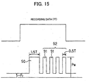
- FIG. 15 shows an example of the recording pulse waveform by the above-mentioned write strategy.
- the example in FTG. 15 is the recording pulse waveform of the portion for recording a mark 7T in the recording data.
- the recording pulse is formed by a single top pulse 90 and a subsequent pulse train (referred to as "multi pulse") 92 including a plurality of pulses 91.
- the top pulse 90 has 1.5T pulse width
- each pulse 91 of the subsequent pulse train 92 has 0.5T pulse width.
- Both the top pulse 90 and the pulse train 92 are pluses whose magnitudes vary between a write power Pw and a read power Pr.
- the top pulse 90 serves as to perform preheat and to form a mark starting portion on the recording surface of the optical disc for the purpose of recording the marks.
- the top pulse 90 brings the recording surface of the optical disc to a melting point.
- the subsequent pulse train 92 forms marks having predetermined length on the recording surface.
- the pulse train 92 is formed by a series of the plurality of pulses 91 having 0.5T pulse width (one period including ON and OFF periods is 1T).
- 0.5T laser irradiation, 0.5T cooling, 0.5T laser irradiation and ... are repeated, and the length of the formed mark is controlled.
- the recording pulse is formed by the single top pulse 90 and the pulse train 92 including the (n-3) pulses 91.
- the marks having the predetermined length are recorded on the recording surface of the optical disc.
- the width of the recording mark is generally expanded according to the increase the recording laser power. Increasing the recording mark width causes problems as follows.
- the recording track On the DVD-R disc, the recording track (groove) is wobbled at a constant frequency, and address pits called “land prepits” (referred to as “LPPs” hereafter) are formed on a land track between the recording tracks.
- LPPs address pits
- the recording marks reach a recording film on the lands and the LPPs, which sometimes causes distortion and destruction of the LPPs.
- a recording and reproducing apparatus cannot detect the LPPs, and recording and reproduction on the disc becomes impossible.
- the present invention has been achieved in order to solve the above problems. It is an object of this invention to provide an information recording apparatus and an information recording method capable of recording marks of appropriate shape at the time of high-speed recording.
- an information recording apparatus which irradiates a laser light on a recording medium and forms recording marks according to a recording signal, including: a driving source which rotationally drives the recording medium at least at a first rotation speed and a second rotation speed higher than the first rotation speed; a light source which emits the laser light; a signal generating unit which generates a recording pulse signal including a top pulse located at a front end portion and having a first magnitude, a last pulse located at a back end portion and having the first magnitude, and an intermediate bias portion located between the top pulse and the last pulse and having a second magnitude, based on the recording signal; and a control unit which irradiates a laser pulse on the recording medium by controlling the light source based on the recording pulse signal, wherein the signal generating unit shifts a position of the top pulse ahead of a position of the top pulse in a case that the recording medium is rotationally driven at the first rotation speed, when the recording medium is rotationally driven at the second rotation speed.
- an information recording method which irradiates a laser light from a light source on a recording medium and forms recording marks according to a recording signal, including: a driving process which rotationally drives the recording medium at least at a first rotation speed and a second rotation speed higher than the first rotation speed; a signal generating process which generates a recording pulse signal including a top pulse located at a front end portion and having a first magnitude, a last pulse located at a back end portion and having the first magnitude, and an intermediate bias portion located between the top pulse and the last pulse and having a second magnitude, based on the recording signal; and a control process which irradiates a laser pulse on the recording medium by controlling the light source based on the recording pulse signal, wherein the signal generating process shifts a position of the top pulse ahead of a position of the top pulse in a case that the recording medium is rotationally driven at the first rotation speed, when the recording medium is rotationally driven at the second rotation speed.
- information is recorded by irradiating the laser light to the recording medium such as a DVD-R and forming the recording marks, for example.
- recording can be performed at least'at two kinds of speed.
- the recording medium is rotationally driven at the first rotation speed.
- the recording medium is rotationally driven at the second rotation speed.
- the recording pulse signal generated based on the recording signal includes the top pulse located at the front end portion and having a first magnitude, the last pulse located at a back end portion and having the first magnitude, and the intermediate bias pulse portion located between the top pulse and the last pulse and having a second magnitude.
- the light source is controlled based on the generated recording pulse signal, and the laser pulse is irradiated on the recording medium. Thereby, the recording marks corresponding to the recording signal are formed on the recording medium.
- the position of the top pulse is shifted ahead of the position of the top pulse when the recording medium is rotationally driven at the first rotation speed.
- the shift quantity of the top pulse is a value between 0.1T and 2.0T.
- the signal generating unit sets the first magnitude to a value between 1.1 times and 2.0 times of the second magnitude.
- an information recording apparatus which irradiates a laser light on a recording medium and forms recording marks according to a recording signal, including: a driving source which rotationally drives the recording medium at least at a first rotation speed and a second rotation speed higher than the first rotation speed; a light source which emits the laser light; a signal generating unit which generates a recording pulse signal including a top pulse located at a front end portion and having a first magnitude, a last pulse located at a back end portion and having the first magnitude, and an intermediate bias portion located between the top pulse and the last pulse and having a second magnitude, based on the recording signal; and a control unit which irradiates a laser pulse on the recording medium by controlling the light source based on the recording pulse signal, wherein the signal generating unit shift a position of the last pulse behind a position of the last pulse in a case that the recording medium is rotationally driven at the first rotation speed, when the recording medium is rotationally driven at the second rotation speed.
- an information recording method which irradiates a laser light from a light source on a recording medium and forms recording marks according to a recording signal, including: a driving process which rotationally drives the recording medium at least at a first rotation speed and a second rotation speed higher than the first rotation speed; a signal generating process which generates a recording pulse signal including a top pulse located at a front end portion and having a first magnitude, a last pulse located at a back end portion and having the first magnitude, and an intermediate bias portion located between the top pulse and the last pulse and having a second magnitude, based on the recording signal; and a control process which irradiates a laser pulse on the recording medium by controlling the light source based on the recording pulse signal, wherein the signal generating process shifts a position of the last pulse behind a position of the last pulse in a case that the recording medium is rotationally driven at the first rotation speed, when the recording medium is rotationally driven at the second rotation speed.
- the information is recorded by irradiating the laser light to the recording medium such as the DVD-R and forming the recording marks, for example.
- recording can be performed at least at two kinds of speed.
- the recording medium is rotationally driven at the first rotation speed.
- the recording medium is rotationally driven at the second rotation speed.
- the recording pulse signal generated based on the recording signal includes the top pulse located at a front end portion and having a first magnitude, the last pulse located at a back end portion and having the first magnitude, and an intermediate bias portion located between the top pulse and the last pulse and having a second magnitude.
- the light source is controlled based on the generated recording pulse signal, and the laser pulse is irradiated on the recording medium. Thereby, the recording marks corresponding to the recording signal are formed on the recording medium.
- the shift quantity of the last pulse is a value between 0.1T and 2.0T.
- the signal generating unit sets the first magnitude to a value between 1.1 times and 2.0 times of the second magnitude.
- an information recording apparatus which irradiates a laser light on a recording medium and forms recording marks according to a recording signal, including: a driving source which rotationally drives the recording medium at least at a first rotation speed and a second rotation speed higher than the first rotation speed; a light source which emits the laser light; a signal generating unit which generates a recording pulse signal including a top pulse located at a front end portion and having a first magnitude, and a pulse train portion having one or a plurality of pulse following the top pulse, based on the recording signal; and a control unit which irradiates a laser pulse on the recording medium by controlling the light source based on the recording pulse signal, wherein the signal generating unit shifts a position of the top pulse ahead of a position of the top pulse in a case that the recording medium is rotationally driven at the first rotation speed, when the recording medium is rotationally driven at the second rotation speed.
- an information recording method which irradiates a laser light from a light source on a recording medium and forms recording marks according to a recording signal, including: a driving process which rotationally drives the recording medium at least at a first rotation speed and a second rotation speed higher than the first rotation speed; a signal generating process which generates a recording pulse signal including a top pulse located at a front end portion and having a first magnitude and, and a pulse train portion having one or a plurality of pulse following the top pulse, based on the recording signal; and a control process which irradiates a laser pulse on the recording medium by controlling the light source based on the recording pulse signal, wherein the signal generating process shifts a position of the top pulse ahead of a position of the top pulse in a case that the recording medium is rotationally driven at the first rotation speed, when the recording medium is rotationally driven at the second rotation speed.
- the information is recorded by irradiating the laser light to the recording medium such as the DVD-R and forming the recording marks, for example.
- recording can be performed at least at two kinds of speed.
- the recording medium is rotationally driven at the first rotation speed.
- the recording medium is rotationally driven at the second rotation speed.
- the recording pulse signal generated based on the recording signal includes the top pulse located at the front end portion and having the first magnitude, and the pulse train portion having one or the plurality of pulse following the top pulse.
- the light source is controlled based on the generated recording pulse signal, and the laser pulse is irradiated on the recording medium. Thereby, the recording marks corresponding to the recording signal are formed on the recording medium.
- the shift quantity of the last pulse is a value between 0.1T and 1.5T.
- the signal generating unit sets a duty ratio of the pulse train portion to a value between 0.3 and 0.9.
- FIG. 1 schematically shows a whole configuration of the information recording and reproducing apparatus according to the embodiment of the present invention.
- An information recording and reproducing apparatus 1 records the information on an optical disc D, and reproduces the information from the optical disc D.
- the optical disc D may be a CD-R (Compact Disc-Recordable) and a DVD-R for recording only once, and a CD-RW (Compact Disc-Rewritable) and a DVD-RW that allow for repeated erasing and recording of information.
- the information recording and reproducing apparatus 1 includes an optical pickup 2 which irradiates a recording beam and a reproducing beam on the optical disc D, a spindle motor 3 which controls rotation of the optical disc D, a recording control unit 10 which controls the recording of the information on the optical disc D, a reproducing control unit 20 which controls reproduction of the information already recorded on the optical disc D, and a servo control unit 30 which executes various kinds of servo control including a spindle servo which controls rotation of the spindle motor 3, and a focus servo and a tracking servo, both of which are relative position control of the optical pickup 2 with respect to the optical disc D.
- the recording control unit 10 receives the recording signal and generates a driving signal SD for driving a laser diode inside the optical pickup 2 by a process described below, and supplies the signal SD to the optical pickup 2.
- the reproducing control unit 20 receives a read-out RF signal Srf which is outputted from the optical pickup 2, and generates and outputs a reproducing signal by executing a predetermined demodulating process and a decoding process to the signal Srf.
- the servo control unit 30 receives the read-out RF signal Srf from the optical pickup 2, and, based on the signal, supplies a servo signal S1 such as a tracking error signal and a focus signal to the optical pickup 2, and also supplies a spindle servo signal S2 to the spindle motor 3.
- a servo signal S1 such as a tracking error signal and a focus signal
- a spindle servo signal S2 to the spindle motor 3.
- FIG. 1 illustrates the information recording and reproducing apparatus as the embodiment of the present invention, it is also possible to apply the present invention to an information recording apparatus dedicated to recording.
- FIG. 2 shows internal configurations of the optical pickup 2 and the recording control unit 10.
- the optical pickup 2 includes a laser diode LD which generates the recording beam for recording the information on the optical disc D and the reproducing beam for reproducing the information from the optical disc D, and a front monitor diode (FMD) 16 which receives the laser light emitted from the laser diode LD and outputs a laser power level signal LDout corresponding to the laser light.
- FMD front monitor diode
- the optical pickup 2 additionally includes a light detector which receives a reflected beam of the reproducing beam by the optical disc Dto generate the read-out RF signal Srf, and well-known components such as an optical system which guides the recording beam, the reproducing beam and the reflected beam to appropriate directions.
- a light detector which receives a reflected beam of the reproducing beam by the optical disc Dto generate the read-out RF signal Srf
- well-known components such as an optical system which guides the recording beam, the reproducing beam and the reflected beam to appropriate directions.
- drawings and detailed explanations thereof are omitted here.
- the recording control unit 10 includes a laser diode (LD) driver 12, an APC (Automatic Power Control) circuit 13, a sample hold (S/H) circuit 14 and a controller 15.
- LD laser diode
- APC Automatic Power Control
- S/H sample hold
- the LD driver 12 supplies, to the laser diode LD, the current corresponding to the recording signal, and records the information on the optical disc D.
- a sample hold circuit 14 samples and holds the level of the laser power level signal LDout at timing prescribed by a sample hold signal APC-S/H. Based on the output signal of the sample hold circuit 14, the APC circuit 13 executes power control of the LD driver 12 so that the read power level of the laser light emitted from the laser diode LD is constant.
- the controller 15 mainly performs a recording operation and an APC operation. First, the recording operation will be explained. In the recording operation, the controller 15 generates switching signals SWR, SWW1 and SWW2 of the switches which control a current quantity supplied to the laser diode LD, and supplies them to the LD driver 12.
- FIG. 3 shows a detailed configuration of the LD driver 12.
- the LD driver 12 includes a current source 17R for a read level, current sources 17W1 and 17W2 for a write level, and switches 18R, 18W1 and 18W2.
- the current source 17R for the read level flows a driving current IR for making the laser diode LD emit the laser light with the read power, and the driving current IR is supplied to the laser diode LD via the switch 18R. Therefore, when the switch 18R is set to an ON state, the driving current IR of the read power is supplied to the laser diode LD. When the switch 18R is set to an OFF state, supplying of the driving current IR is stopped.
- the quantity of the driving current IR from the current source 17R varies by a control signal SAPC.
- the current sources 17W1 and 17W2 for the write level flow driving current IW1 and IW2, to the laser diode LD, for emitting the laser light with the write power respectively.
- the driving current IW1 is supplied to the laser diode LD via the switch 18W1
- the driving current IW2 is supplied to the laser diode LD via the switch 18W2.
- two levels of write powers i.e., a first write power Ph and a second write power Pm lower than the first write power Ph are used (see FIG. 5).
- a first write power Ph a second write power Pm lower than the first write power Ph
- a second write power Pm a total driving current of the driving currents IR and IW1
- the laser diode is driven by the second write power Pm.
- the switch 18W2 is set to the ON state with the switches 18R and 18W1 in the ON state, the driving current IW2 is additionally supplied to the laser diode LD.
- a total driving current of the driving currents IR, IW1 and IW2 is flown to the laser diode LD, and the laser diode LD is driven by the first write power Ph.
- the switch 18W1 is set to the OFF state, the supply of the driving current IW1 is stopped.
- the switch 18W2 is set to the OFF state, the supply of the driving current IW2 is stopped.
- FIG. 4 shows a relation between the driving current supplied to the laser diode LD and the output power of the laser light emitted from the laser diode LD.
- the driving current IR when the driving current IR is supplied to the laser diode LD, the laser light is emitted with the read power PR.
- the driving current IW1 when further adding the driving current IW1, the laser light is emitted with the second write power Pm.
- the driving current IW2 By further adding the driving current IW2, the laser light is emitted with the first write power Ph.
- the driving current IR is always supplied, and the laser light is emitted with the read power PR. Additionally, if the driving currents IW1 and IW2 are added in accordance with the recording pulse, the first write power Ph or the second write power Pm is applied, and the information is recorded on the optical disc.
- the APC operation is for adjusting the driving current level supplied from the LD driver 12 to the laser diode LD so that the level of the read power of the laser light outputted by the laser diode LDbecomes constant.
- the driving signal SD from the recording control unit 10 is adjusted so that the level of the read power is constant.
- the APC operation is performed as follows.
- the controller 15 generates the recording pulse corresponding to the recording signal as described above, and drives the LD driver 12 by the recording pulse to emit the laser light from the laser diode LD.
- the front monitor diode 16 which is provided near the laser diode LD in the optical pickup 2, receives the laser light emitted from the laser diode LD, and generates the laser power level signal LDout indicating its level to supply it to the sample hold circuit 14.
- the sample hold circuit 14 samples the laser power level signal LDout supplied from the front monitor diode 16 at the timing given by the sample hold signal APC-S/H inputted from the controller 15, and holds its level for a predetermined period.
- the sample hold signal APC-S/H outputted from the controller 15 is a pulse indicating a period (referred to as "APC period") in which the APC is executed.
- the sample hold circuit 14 holds the level of the laser power level signal LDout in the APC period in the space period of the recording signal, and supplies it to the APC circuit 13.
- the APC circuit 13 supplies the control signal SAPC to the LD driver 12 so that the level of the laser power level signal LDout in the APC period becomes constant.
- control signal SAPC is inputted to the current source 17R for the read level in the LD driver 12.
- the current IR flowing from the current source 17R for the read level varies.
- the APC is executed so that the read power level obtained by the laser diode LD becomes constant.
- FIG. 5 shows the recording pulse waveform by a basic write strategy.
- the recording pulse waveform by the basic write strategy is formed by three portions, i.e., a top pulse 40, an intermediate bias portion 41 and a last pulse 42. In portions other than those portions, the recording pulse waveform is maintained at the level of the read power PR.
- the write powers of two values are utilized for the basic write strategy.
- the top pulse 40 and the last pulse 42 have the first write power Ph, and the intermediate bias portion 41 has the second write power Pm. Though the second write power Pm is higher than the read power PR, it is set to be lower than the first write power Ph.
- the top pulse 40 preheats the recording surface of the optical disc, and forms the mark starting portion for the purpose of recording themark.
- a time width of the intermediate bias portion 41 varies in accordance with the length of the recording data.
- the last pulse 42 mainly has a function to adjust a shape of the back end portion of the mark.
- the length of the formed recording mark is controlled by a top pulse width Ttop, a last pulse width T1p, a width Tp from the front end portion of the top pulse to the back end portion of the last pulse, and the first write power Ph, and the width of the formed recording mark is controlled by the second write power Pm.
- FIG. 6 shows the recording pulse waveform corresponding to each mark length to be recorded.
- the recording data is 8-16 modulated, and has the mark period and the space period of 3T to 11T and 14T lengths.
- a front edge of the recording pulse waveform is always located at the position behind, 1.5T from the front edge of the recording data, irrespective of the mark length.
- the recording pulse waveforms of the recording data of 3T and 4T do not have the intermediate bias portion 41, and the top pulse 40 and the last pulse 42 are synthesized to form the single pulse.
- the power of this pulse is the first write power Ph, which is identical to the powers of the top pulse and the last pulse.
- the length of the intermediate bias portion 41 increases in accordance with each length.
- the pulse widths of the top pulse 40 and the last pulse 42 are basically almost constant respectively, and the widths do not have to be largely varied in accordance with the recording data length, differently from the intermediate bias portion 41.
- the top pulse and the last pulse are synthesized to form the single pulse waveform.
- the recording pulse waveform can also be determined so that the intermediate bias portion is provided.
- the clock When the recording speed is higher, the clock also becomes higher correspondingly. Therefore, not only the recording data of 3T and 4T, but also the recording data equal to or larger than 5T may have the single-pulse-type recording pulse waveforms without the intermediate bias portion.
- the improved write strategy is based on the above-mentioned basic write strategy, and is further suitable for the high-speed recording.
- the recording is performed at the normal speed by using the above-mentioned basic write strategy, and the recording can be performed at a speed higher than the normal speed by using the improved write strategy, which will be explained as follows.
- the recording laser power also has to be increased correspondingly to the increase of the disc rotation speed in order to appropriately form the recording marks.
- the recording laser power is increased too much, the width of the recording mark formed on the recording track of the disc becomes wider than needed. As a result, a problem occurs, e.g., a malfunction occurs to the detection of the LPP.
- the improved write strategy of the present invention can form the recording marks of appropriate width, even when the disc rotation speed is increased for the high-speed recording.
- the write power Pm of the intermediate bias portion 41 that affects the width of the formed recording mark most in the basic write strategy. Therefore, if the write power Pm is decreased, the width of the recording mark becomes small, and a modulation can be decreased.
- the modulation is a value indicating a ratio (I14/I14H) of an magnitude I14 of the reproducing signal corresponding to a longest recording mark and a longest space, with respect to a difference I14H between a peak value and the zero level of the reproducing signal corresponding to a longest space portion (14T space). According to a DVD-R standard book, the modulation equal to or larger than 0.60 (60%) is required.
- the modulation is decreased by decreasing only the write power Pm of the intermediate bias portion 41, a distortion occurs to the reproduced waveform.
- problems occur, such as the increase of jitters in recording and reproduction, the increase of read-out errors of the recording marks, the increase of error rates, and the like.
- the reproducing process is executed by using a distorted reproduced waveform, a probability of erroneous detection of the recording data is increased.
- the recording is performed by decreasing only the write power Pm in the intermediate bias portion 41, the shape of the recording mark formed on the disc becomes wide at the front end portion and the back end portion corresponding to the top pulse 40 and the last pulse 42, and becomes narrow only at the intermediate portion corresponding to the intermediate bias portion 41.
- the wide front and back end portions give an adverse effect to the shape of the LPP.
- the write power Ph corresponding to the top pulse 40 and the last pulse 42 affects the length of the formed recordingmark. Therefore, if the write power Ph corresponding to the top pulse 40 and the last pulse 42 is decreased for suppressing the distortion of the reproduced waveform, the length of the recordingmark becomes short, and the erroneous detection of the recording data may occur.
- the width Tp from the front end portion of the top pulse to the back end portion of the last pulse is enlarged by shifting the position of the top pulse 40 ahead by a predetermined quantity or by shifting the position of the last pulse 42 behind by a predetermined quantity, and it is thereby prevented that the length of the recording mark is shortened.
- two improved points below are prescribed to be simultaneously performed:
- extension of the recording mark width is suppressed by reducing the write power Pm of the intermediate bias portion 41.
- the distortion occurs to the reproduced waveform by reducing the write power Pm
- the distortion is suppressed by reducing the write power Ph corresponding to the top pulse 40 and the last pulse 42 as the need arises.
- the lengths of the whole recording marks are shortened by reducing the write power Ph, by shifting the position of the top pulse 40 ahead or shifting the position of the last pulse 42 behind according to the shortened quantity, the lengths of the whole formed recording marks are maintained to appropriate lengths.
- the extension of the recording mark width can be prevented, and the occurrence of the distortion can also be suppressed.
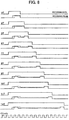
- FIGS. 7A to 7E show examples of the recording pulse waveforms by the improved write strategy of the present invention.
- FIG. 7A is the waveform of the recording data
- FIG. 7B is the recording pulse waveform by the basic write strategy.
- FIGS. 7C and 7D are the examples of the recording pulse waveforms by the improved write strategy, and
- FIG. 7E is a clock waveform.
- the position of the top pulse 40 is shifted ahead by 0.5T in comparison with the position of the top pulse 40 of the recording pulse waveform by the basic write strategy shown in FIG. 7B.
- the shift quantity is merely an example, and the value between 0.1T to 1.5T can be taken dependently upon the optical disc.
- the write power Pm of the intermediate bias portion 41 by the improved write strategy becomes smaller than the write power Pm of the intermediate bias portion 41 of the recording pulse waveform by the basic write strategy.
- the write power Ph of the top pulse 40 and the last pulse 42 by the improved write strategy becomes smaller than the write power Ph of the top pulse 40 and the last pulse 42 of the recording pulse waveform by the basic write strategy, and can take the value of 1.1 to 2. 0-times of the write power Pm of the intermediate bias portion 41 by the improved write strategy.
- the position of the last pulse 42 is shifted behind by 0. 5T in comparison with the example of the recording pulse waveform by the basic write strategy shown in FIG. 7B.
- the shift quantity is merely an example, and can take the value between 0.1T and 1.5T dependently upon the optical disc.
- the write power Pm of the intermediate bias portion 41 becomes smaller than the write power Pm of the intermediate bias portion 41 of the recording pulse waveform by the basic write strategy.
- the write power Ph of the top pulse 40 and the last pulse 42 of the recording pulse waveform becomes smaller than the write power Ph of the top pulse 40 and the last pulse 42 of the recording pulse waveform by the basic write strategy, and can take the value between 1.1 times and 2.0 times of the write power Pm of the intermediate bias portion 41 by the improved write strategy.
- Those are identical to the example of the recording pulse waveform shown in FIG. 7C.
- the improved write strategy of the present invention it is dispensable to reduce the write power Ph corresponding to the top pulse 40 and the last pulse 42 (i.e., the Improved point 3).
- the quantity of reducing the write power Pm of the intermediate bias portion 41 is large, unless the write power Ph is reduced to some extent in accordance with the quantity, the distortion of the signal waveform becomes large.
- whether the write power Ph is reduced or not, or how much the write power Ph is reduced if reduced are determined dependently on the quantity of shifting the top pulse or the last pulse by the Improved point 1, and on the quantity of reducing the write power Pm of the intermediate bias portion by the Improved point 2.
- FIG. 8 shows the recording pulse waveforms corresponding to the recording data 3T to 11T and 14T by the improved write strategy of the present invention. It is noted that the recording pulse waveforms of 3T to 11T and 14T by the basic write strategy at the same recording speed are indicated by broken lines, for the sake of comparison. According to the present improved write strategy, the recording pulse waveforms corresponding to the recording data of 3T and 4T do not include the intermediate bias portions, but the recording pulse waveforms may include the intermediate bias portions. As the speed increases (e.g., 6-times speed, 8-times speed, ...) at the time of the high-speed recording, even the recording pulse waveform corresponding to much longer recording data (e.g., 5T, 6T, ...) may include no intermediate bias portion.
- the speed increases e.g., 6-times speed, 8-times speed, ...) at the time of the high-speed recording, even the recording pulse waveform corresponding to much longer recording data (e.g., 5T, 6T, ...) may include no
- the top pulse is shifted ahead by 0.5T.
- the shift quantity is merely the example, and the values between 0.1T and 1.5T can be taken dependently upon the optical disc, as described above. However, even when the position of the top pulse 40 is shifted ahead, the front edge of the top pulse is never located ahead of the front edge of the recording data.
- the shift quantity of the top pulse is identical. However, the top pulse may be shifted at an identical rate in accordance with the length of each recording pulse.
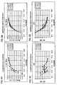
- STG1 indicates a characteristic in a case that the recording pulse waveform by the basic 'write strategy shown in FIG. 7B is used.
- STG2 is a characteristic of a comparative example in that the write power Pm of the intermediate bias portion 41 is made smaller and the pulse widths of the top pulse 40 and the last pulse 42 are made longer, in the recording pulse waveform by the identical basic write strategy.
- STG3 is a characteristic of a comparative example in that the write power Pm of the intermediate bias portion 41 is made much smaller than the case of STG2 and the pulse widths of the top pulse 40 and the last pulse 42 are made much longer than the case of STG2, in the recording pulse waveform by the identical basic write strategy.
- STG4 is a characteristic of the recording pulse waveform by the improved write strategy shown in FIG. 7C, in that the position of the top pulse 40 is shifted ahead by 0.5T and the write power Pm of the intermediate bias portion 41 is decreased.
- STG5 is also a characteristic of the recording pulse waveform by the improved write strategy, in that the position of the top pulse 40 is shifted ahead by 1.0T and the write power Pm of the intermediate bias portion 41 is made much smaller than the case of STG4.
- the horizontal axes indicate the write power Pm of the intermediate bias portion, and the vertical axes indicate the modulation.
- the horizontal axes similarly indicate the write power Pm of the intermediate bias portion, and the vertical axes indicate an AR.
- the AR Absolute Ratio after recording
- the AR is a ratio (AP(max)/AP(min)) of a maximum AP (max) and a minimum AP (min) of an LPP signal appearing in a push-pull signal after recording, and is a value indicating quality of the LPP.
- AR Absoluted-Rdisc standard book
- AR>15% is required.
- AR>10% is required.
- the improved write strategy can effectively decrease the modulation by the decrease of the write power Pm of the intermediate bias portion.
- the write power Pm of the intermediate bias portion when the write power Pm of the intermediate bias portion is decreased, the AR value remarkably increases.
- the characteristics STG2 and STG3 of the comparative examples even if the write power Pm of the intermediate bias portion is decreased, the distortion increases, and the AR value does not increase so much. Therefore, the decrease of the write power Pm of the intermediate bias portion in the improved write strategy more effectively contributes to the increase of the AR value, and it can be prevented that the formed recording mark affects the LPPs on the land track.
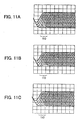
- FIGS. 11A to 11C show waveform examples of the reproducing signal of the above-mentioned comparative examples and the improved write strategy.
- FIG. 11A shows the reproducing signal waveform in a case that the recording is performed by the basic write strategy (STG1) for comparison.
- FIG. 11B shows the example of the reproducing signal waveform of the mark recorded by the above-mentioned comparative example (STG3).
- FIG. 11C shows the example of the reproducing signal waveform of the mark recorded by the improved write strategy (STG5) of the present invention. If the waveform around a reference numeral 110 in each graph is taken notice of, though the lowest level of each waveform corresponding to 3T to 11T and 14T is equal in the reproducing signal waveform shown in FIG.
- the modulation is large, and the effect given to the LPPs is also large.
- the reproducing signal waveform of the comparative example shown in FIG. 11B though the modulation becomes smaller in comparison with FIG. 11A, the lowest level of each waveform is not equal.
- the lowest levels of the reproducing signal waveforms corresponding to the central portions of the recording marks longer than 7T to 8T become high, and the waveforms are distorted. This is because the long recording mark is formed with the narrow center portion, like a shape of a gourd.
- the modulation becomes small in comparison with FIG. 11A, and the lowest level of the reproducing signal waveform of each recording mark is equal.
- the above-mentioned improved write strategy is based on the basic write strategy as shown in FIG. 5.
- the concept of the improved write strategy of the present invention can be similarly applied to the normal write strategy shown in FIG. 15, too.
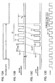
- FIGS. 12A to 12D and FIGS. 13A to 13D show application examples in a case that the concept of the improved write strategy of the present invention is applied to the normal write strategy.
- FIG. 12A shows the recording data waveform
- FIG. 12B shows the recording pulse waveform before the improvement of the normal write strategy, formed by the top pulse and the pulse train.
- FIG. 12C shows an example of the recording pulse waveform in a case that the concept of the improved write strategy of the present invention is applied to the normal write strategy.
- the position of a top pulse 70 is shifted ahead by 0.5T.
- the pulse width of each pulse 71 forming a pulse train 72 is decreased.
- FIG. 13A shows the recording data waveform
- FIG. 13B shows the recording pulse waveform before the improvement of the normal write strategy, formed by the top pulse and the pulse train.
- FIG. 13C shows the example of the recording pulse waveform in the case that the concept of the improved write strategy of the present invention is applied to the normal write strategy.
- each pulse 71 forming the pulse train 72 is equally moved in accordance with the shift quantity of the top pulse 70. Namely, according to a rate of increasing time width of the whole recording pulses by movement of the top pulse 70, the position of each pulse 71 is shifted. Identically to FIG. 12C, the pulse width of each pulse 71 forming the pulse train 72 is decreased. This is equivalent to decreasing the level of the intermediate bias portion in the above-mentioned basic write strategy.
- the present invention is not limited to the above-mentioned embodiment.
- the position of the top pulse is shifted ahead by the predetermined quantity
- the position of the last pulse is shifted behind by the predetermined quantity.
- the recording mark length may be controlled to be a desired length.
- the position of the top pulse 40 of the basic write strategy shown in FIG. 14C can be shifted ahead between 0.1T and 2.0T, dependently upon the optical disc, in comparison with the top pulse of the basic write strategy shown in FIG. 14B.
- the write power Pm of the intermediate bias portion 41 by the improved write strategy becomes smaller than the write power Pm of the intermediate bias portion 41 of the recording pulse waveform by the basic write strategy, too.
- the write power Ph of the top pulse 40 and the last pulse 42 by the improved write strategy becomes smaller than the write power Ph of the top pulse 40 and the last pulse 42 of the recording pulse waveform by the basic write strategy, and can take the value between 1.1 times and 2.0 times of the write power Pm in the intermediate bias portion 41 by the improved write strategy.
- the recording pulse waveform by the improved write strategy shown in FIG. 14D indicates a state that the position of the last pulse 42 is shifted behind by 0.1T to 2. 0T in comparison with the example of the recording pulse waveform by the basic write strategy shown in FIG. 14B, and hence the detailed explanation thereof is omitted here.
- the present invention is applied to the recording pulse signal including the last pulse 42.
- the present invention can also be applied to the recording pulse signal which does not include the last pulse 42.
- the increase of the formed recording mark width can be suppressed without the distortion occurring to the reproducing signal waveform, by shifting the position of the top pulse ahead or by shifting the position of the last pulse behind. Therefore, it can be prevented that the LPPs on the land track neighboring the recording track are distorted and destroyed by the recording marks. Also, since the distortion does not occur to the reproducing signal waveform, jitter and an error of reading out of the recording mark can be prevented.
- the information recording apparatus and the information recording method according to the present invention can be utilized when information is recorded on an optical disc by using the laser light and the like.
Landscapes
- Optical Recording Or Reproduction (AREA)
- Optical Head (AREA)
Applications Claiming Priority (3)
| Application Number | Priority Date | Filing Date | Title |
|---|---|---|---|
| JP2002173609 | 2002-06-14 | ||
| JP2002173609 | 2002-06-14 | ||
| PCT/JP2003/004233 WO2003107332A1 (ja) | 2002-06-14 | 2003-04-02 | 情報記録装置および情報記録方法 |
Publications (3)
| Publication Number | Publication Date |
|---|---|
| EP1515314A1 true EP1515314A1 (de) | 2005-03-16 |
| EP1515314A4 EP1515314A4 (de) | 2009-04-15 |
| EP1515314B1 EP1515314B1 (de) | 2010-07-14 |
Family
ID=29727921
Family Applications (1)
| Application Number | Title | Priority Date | Filing Date |
|---|---|---|---|
| EP03760131A Expired - Lifetime EP1515314B1 (de) | 2002-06-14 | 2003-04-02 | Informationsaufzeichnungsvorrichtung und informationsaufzeichnungsverfahren |
Country Status (6)
| Country | Link |
|---|---|
| US (1) | US7161888B2 (de) |
| EP (1) | EP1515314B1 (de) |
| JP (1) | JP4336646B2 (de) |
| AU (1) | AU2003236342A1 (de) |
| DE (1) | DE60333366D1 (de) |
| WO (1) | WO2003107332A1 (de) |
Cited By (2)
| Publication number | Priority date | Publication date | Assignee | Title |
|---|---|---|---|---|
| EP1826751A1 (de) * | 2006-02-22 | 2007-08-29 | Ricoh Company, Ltd. | Aufzeichnungsverfahren für ein beschreibbares DVD-Medium auf Farbstoffbasis und Aufzeichnungsgerät |
| US7639578B2 (en) * | 2004-03-24 | 2009-12-29 | Taiyo Yuden Co., Ltd. | Optical recording apparatus |
Families Citing this family (4)
| Publication number | Priority date | Publication date | Assignee | Title |
|---|---|---|---|---|
| JPWO2005109409A1 (ja) * | 2004-05-11 | 2008-03-21 | パイオニア株式会社 | 情報記録装置及び方法、並びにコンピュータプログラム |
| CN1734584A (zh) * | 2004-08-13 | 2006-02-15 | 皇家飞利浦电子股份有限公司 | 一种确定用于光盘刻写的参数的方法及装置 |
| JP2008294913A (ja) * | 2007-05-28 | 2008-12-04 | Panasonic Corp | 固体撮像装置およびその駆動方法 |
| JP4537430B2 (ja) * | 2007-07-31 | 2010-09-01 | 太陽誘電株式会社 | 光ディスク記録方法、光ディスク記録再生装置及び光ディスク |
Family Cites Families (5)
| Publication number | Priority date | Publication date | Assignee | Title |
|---|---|---|---|---|
| JPH09282660A (ja) | 1996-04-17 | 1997-10-31 | Hitachi Ltd | 情報記録方法及び情報記録装置 |
| JP3748089B2 (ja) * | 1996-09-18 | 2006-02-22 | ソニー株式会社 | データ記録装置およびデータ記録方法 |
| JP2001110053A (ja) * | 1999-10-14 | 2001-04-20 | Ricoh Co Ltd | 情報記録方法及びその装置 |
| JP2001176073A (ja) | 1999-12-20 | 2001-06-29 | Ricoh Co Ltd | 光記録媒体の記録方法および記録装置 |
| JP2001274358A (ja) | 2000-03-23 | 2001-10-05 | Seiko Epson Corp | セラミックス薄膜デバイスの製造方法及びセラミックス薄膜デバイス |
-
2003
- 2003-04-02 US US10/517,525 patent/US7161888B2/en not_active Expired - Fee Related
- 2003-04-02 DE DE60333366T patent/DE60333366D1/de not_active Expired - Lifetime
- 2003-04-02 WO PCT/JP2003/004233 patent/WO2003107332A1/ja not_active Ceased
- 2003-04-02 EP EP03760131A patent/EP1515314B1/de not_active Expired - Lifetime
- 2003-04-02 AU AU2003236342A patent/AU2003236342A1/en not_active Abandoned
- 2003-04-02 JP JP2004514064A patent/JP4336646B2/ja not_active Expired - Fee Related
Non-Patent Citations (2)
| Title |
|---|
| No further relevant documents disclosed * |
| See also references of WO03107332A1 * |
Cited By (3)
| Publication number | Priority date | Publication date | Assignee | Title |
|---|---|---|---|---|
| US7639578B2 (en) * | 2004-03-24 | 2009-12-29 | Taiyo Yuden Co., Ltd. | Optical recording apparatus |
| EP1826751A1 (de) * | 2006-02-22 | 2007-08-29 | Ricoh Company, Ltd. | Aufzeichnungsverfahren für ein beschreibbares DVD-Medium auf Farbstoffbasis und Aufzeichnungsgerät |
| US7729223B2 (en) | 2006-02-22 | 2010-06-01 | Ricoh Company, Ltd. | Recording method for dye-based recordable DVD medium and recording apparatus |
Also Published As
| Publication number | Publication date |
|---|---|
| US7161888B2 (en) | 2007-01-09 |
| EP1515314A4 (de) | 2009-04-15 |
| DE60333366D1 (de) | 2010-08-26 |
| EP1515314B1 (de) | 2010-07-14 |
| WO2003107332A1 (ja) | 2003-12-24 |
| JP4336646B2 (ja) | 2009-09-30 |
| US20060098547A1 (en) | 2006-05-11 |
| JPWO2003107332A1 (ja) | 2005-10-20 |
| AU2003236342A1 (en) | 2003-12-31 |
Similar Documents
| Publication | Publication Date | Title |
|---|---|---|
| JP4560251B2 (ja) | 情報記録装置および情報記録方法 | |
| US20070195678A1 (en) | Information recording apparatus and information recording method | |
| EP1347444B1 (de) | Verfahren und Vorrichtung zur Aufzeichnung von Daten auf einem optischen Aufzeichnungsmedium | |
| EP1515314B1 (de) | Informationsaufzeichnungsvorrichtung und informationsaufzeichnungsverfahren | |
| EP1288923B1 (de) | Informationsaufzeichnungsvorrichtung und Informationsaufzeichnungsverfahren | |
| EP1233411B1 (de) | Vorrichtung und Verfahren zur Erzeugung von optischen Aufzeichnungspulsen | |
| US7609601B2 (en) | Information recording apparatus, information recording method and information recording program | |
| US7742371B2 (en) | Information recording/reproducing device, information recording/reproducing method, and information recording/reproducing program | |
| US7719943B2 (en) | Information recording device and information recording method | |
| US7586823B2 (en) | Information recording apparatus and information recording method | |
| US7304928B2 (en) | Laser power control technique and apparatus for recording and reproducing data in and from optical disk under laser power control | |
| KR101126089B1 (ko) | 기록 펄스 생성 장치 및 정보 기록 장치 | |
| US7787335B2 (en) | Information recording device, information recording method, and information recording program | |
| US20060176795A1 (en) | Optical recording system and method | |
| JP2007134044A (ja) | 情報記録装置および情報記録方法 | |
| JP2007103012A (ja) | 情報記録装置および情報記録方法 | |
| JP2007103013A (ja) | 情報記録装置および情報記録方法 | |
| JP2006048836A (ja) | 情報記録方法とレーザ駆動回路と情報記録装置 | |
| HK1094621B (en) | Information recording apparatus and information recording method | |
| HK1067772A1 (en) | Apparatus for recording data on optical recording medium |
Legal Events
| Date | Code | Title | Description |
|---|---|---|---|
| PUAI | Public reference made under article 153(3) epc to a published international application that has entered the european phase |
Free format text: ORIGINAL CODE: 0009012 |
|
| 17P | Request for examination filed |
Effective date: 20041230 |
|
| AK | Designated contracting states |
Kind code of ref document: A1 Designated state(s): AT BE BG CH CY CZ DE DK EE ES FI FR GB GR HU IE IT LI LU MC NL PT RO SE SI SK TR |
|
| AX | Request for extension of the european patent |
Extension state: AL LT LV MK |
|
| DAX | Request for extension of the european patent (deleted) | ||
| RBV | Designated contracting states (corrected) |
Designated state(s): DE FR GB |
|
| A4 | Supplementary search report drawn up and despatched |
Effective date: 20090316 |
|
| GRAP | Despatch of communication of intention to grant a patent |
Free format text: ORIGINAL CODE: EPIDOSNIGR1 |
|
| GRAS | Grant fee paid |
Free format text: ORIGINAL CODE: EPIDOSNIGR3 |
|
| GRAA | (expected) grant |
Free format text: ORIGINAL CODE: 0009210 |
|
| AK | Designated contracting states |
Kind code of ref document: B1 Designated state(s): DE FR GB |
|
| REG | Reference to a national code |
Ref country code: GB Ref legal event code: FG4D |
|
| REF | Corresponds to: |
Ref document number: 60333366 Country of ref document: DE Date of ref document: 20100826 Kind code of ref document: P |
|
| RAP2 | Party data changed (patent owner data changed or rights of a patent transferred) |
Owner name: PIONEER CORPORATION |
|
| PLBE | No opposition filed within time limit |
Free format text: ORIGINAL CODE: 0009261 |
|
| STAA | Information on the status of an ep patent application or granted ep patent |
Free format text: STATUS: NO OPPOSITION FILED WITHIN TIME LIMIT |
|
| 26N | No opposition filed |
Effective date: 20110415 |
|
| REG | Reference to a national code |
Ref country code: DE Ref legal event code: R097 Ref document number: 60333366 Country of ref document: DE Effective date: 20110415 |
|
| REG | Reference to a national code |
Ref country code: GB Ref legal event code: 746 Effective date: 20120326 |
|
| REG | Reference to a national code |
Ref country code: DE Ref legal event code: R084 Ref document number: 60333366 Country of ref document: DE Effective date: 20120322 |
|
| REG | Reference to a national code |
Ref country code: FR Ref legal event code: PLFP Year of fee payment: 14 |
|
| REG | Reference to a national code |
Ref country code: FR Ref legal event code: PLFP Year of fee payment: 15 |
|
| REG | Reference to a national code |
Ref country code: FR Ref legal event code: PLFP Year of fee payment: 16 |
|
| PGFP | Annual fee paid to national office [announced via postgrant information from national office to epo] |
Ref country code: GB Payment date: 20180329 Year of fee payment: 16 |
|
| PGFP | Annual fee paid to national office [announced via postgrant information from national office to epo] |
Ref country code: FR Payment date: 20180315 Year of fee payment: 16 |
|
| PGFP | Annual fee paid to national office [announced via postgrant information from national office to epo] |
Ref country code: DE Payment date: 20180320 Year of fee payment: 16 |
|
| REG | Reference to a national code |
Ref country code: DE Ref legal event code: R119 Ref document number: 60333366 Country of ref document: DE |
|
| GBPC | Gb: european patent ceased through non-payment of renewal fee |
Effective date: 20190402 |
|
| PG25 | Lapsed in a contracting state [announced via postgrant information from national office to epo] |
Ref country code: GB Free format text: LAPSE BECAUSE OF NON-PAYMENT OF DUE FEES Effective date: 20190402 Ref country code: DE Free format text: LAPSE BECAUSE OF NON-PAYMENT OF DUE FEES Effective date: 20191101 |
|
| PG25 | Lapsed in a contracting state [announced via postgrant information from national office to epo] |
Ref country code: FR Free format text: LAPSE BECAUSE OF NON-PAYMENT OF DUE FEES Effective date: 20190430 |