EP1515293A1 - Dispositif de détection d'obstacle comportant un système d'imagerie stéréoscopique incluant deux capteurs optiques - Google Patents
Dispositif de détection d'obstacle comportant un système d'imagerie stéréoscopique incluant deux capteurs optiques Download PDFInfo
- Publication number
- EP1515293A1 EP1515293A1 EP04292151A EP04292151A EP1515293A1 EP 1515293 A1 EP1515293 A1 EP 1515293A1 EP 04292151 A EP04292151 A EP 04292151A EP 04292151 A EP04292151 A EP 04292151A EP 1515293 A1 EP1515293 A1 EP 1515293A1
- Authority
- EP
- European Patent Office
- Prior art keywords
- detection device
- obstacle detection
- optical sensors
- sensors
- lines
- Prior art date
- Legal status (The legal status is an assumption and is not a legal conclusion. Google has not performed a legal analysis and makes no representation as to the accuracy of the status listed.)
- Ceased
Links
Images

Classifications
-
- B—PERFORMING OPERATIONS; TRANSPORTING
- B60—VEHICLES IN GENERAL
- B60Q—ARRANGEMENT OF SIGNALLING OR LIGHTING DEVICES, THE MOUNTING OR SUPPORTING THEREOF OR CIRCUITS THEREFOR, FOR VEHICLES IN GENERAL
- B60Q1/00—Arrangement of optical signalling or lighting devices, the mounting or supporting thereof or circuits therefor
- B60Q1/0017—Devices integrating an element dedicated to another function
- B60Q1/0023—Devices integrating an element dedicated to another function the element being a sensor, e.g. distance sensor, camera
-
- B—PERFORMING OPERATIONS; TRANSPORTING
- B60—VEHICLES IN GENERAL
- B60Q—ARRANGEMENT OF SIGNALLING OR LIGHTING DEVICES, THE MOUNTING OR SUPPORTING THEREOF OR CIRCUITS THEREFOR, FOR VEHICLES IN GENERAL
- B60Q1/00—Arrangement of optical signalling or lighting devices, the mounting or supporting thereof or circuits therefor
- B60Q1/02—Arrangement of optical signalling or lighting devices, the mounting or supporting thereof or circuits therefor the devices being primarily intended to illuminate the way ahead or to illuminate other areas of way or environments
- B60Q1/04—Arrangement of optical signalling or lighting devices, the mounting or supporting thereof or circuits therefor the devices being primarily intended to illuminate the way ahead or to illuminate other areas of way or environments the devices being headlights
- B60Q1/06—Arrangement of optical signalling or lighting devices, the mounting or supporting thereof or circuits therefor the devices being primarily intended to illuminate the way ahead or to illuminate other areas of way or environments the devices being headlights adjustable, e.g. remotely-controlled from inside vehicle
- B60Q1/08—Arrangement of optical signalling or lighting devices, the mounting or supporting thereof or circuits therefor the devices being primarily intended to illuminate the way ahead or to illuminate other areas of way or environments the devices being headlights adjustable, e.g. remotely-controlled from inside vehicle automatically
- B60Q1/085—Arrangement of optical signalling or lighting devices, the mounting or supporting thereof or circuits therefor the devices being primarily intended to illuminate the way ahead or to illuminate other areas of way or environments the devices being headlights adjustable, e.g. remotely-controlled from inside vehicle automatically due to special conditions, e.g. adverse weather, type of road, badly illuminated road signs or potential dangers
-
- B—PERFORMING OPERATIONS; TRANSPORTING
- B60—VEHICLES IN GENERAL
- B60Q—ARRANGEMENT OF SIGNALLING OR LIGHTING DEVICES, THE MOUNTING OR SUPPORTING THEREOF OR CIRCUITS THEREFOR, FOR VEHICLES IN GENERAL
- B60Q1/00—Arrangement of optical signalling or lighting devices, the mounting or supporting thereof or circuits therefor
- B60Q1/02—Arrangement of optical signalling or lighting devices, the mounting or supporting thereof or circuits therefor the devices being primarily intended to illuminate the way ahead or to illuminate other areas of way or environments
- B60Q1/04—Arrangement of optical signalling or lighting devices, the mounting or supporting thereof or circuits therefor the devices being primarily intended to illuminate the way ahead or to illuminate other areas of way or environments the devices being headlights
- B60Q1/06—Arrangement of optical signalling or lighting devices, the mounting or supporting thereof or circuits therefor the devices being primarily intended to illuminate the way ahead or to illuminate other areas of way or environments the devices being headlights adjustable, e.g. remotely-controlled from inside vehicle
- B60Q1/08—Arrangement of optical signalling or lighting devices, the mounting or supporting thereof or circuits therefor the devices being primarily intended to illuminate the way ahead or to illuminate other areas of way or environments the devices being headlights adjustable, e.g. remotely-controlled from inside vehicle automatically
- B60Q1/10—Arrangement of optical signalling or lighting devices, the mounting or supporting thereof or circuits therefor the devices being primarily intended to illuminate the way ahead or to illuminate other areas of way or environments the devices being headlights adjustable, e.g. remotely-controlled from inside vehicle automatically due to vehicle inclination, e.g. due to load distribution
- B60Q1/115—Arrangement of optical signalling or lighting devices, the mounting or supporting thereof or circuits therefor the devices being primarily intended to illuminate the way ahead or to illuminate other areas of way or environments the devices being headlights adjustable, e.g. remotely-controlled from inside vehicle automatically due to vehicle inclination, e.g. due to load distribution by electric means
-
- B—PERFORMING OPERATIONS; TRANSPORTING
- B60—VEHICLES IN GENERAL
- B60Q—ARRANGEMENT OF SIGNALLING OR LIGHTING DEVICES, THE MOUNTING OR SUPPORTING THEREOF OR CIRCUITS THEREFOR, FOR VEHICLES IN GENERAL
- B60Q1/00—Arrangement of optical signalling or lighting devices, the mounting or supporting thereof or circuits therefor
- B60Q1/26—Arrangement of optical signalling or lighting devices, the mounting or supporting thereof or circuits therefor the devices being primarily intended to indicate the vehicle, or parts thereof, or to give signals, to other traffic
- B60Q1/50—Arrangement of optical signalling or lighting devices, the mounting or supporting thereof or circuits therefor the devices being primarily intended to indicate the vehicle, or parts thereof, or to give signals, to other traffic for indicating other intentions or conditions, e.g. request for waiting or overtaking
- B60Q1/525—Arrangement of optical signalling or lighting devices, the mounting or supporting thereof or circuits therefor the devices being primarily intended to indicate the vehicle, or parts thereof, or to give signals, to other traffic for indicating other intentions or conditions, e.g. request for waiting or overtaking automatically indicating risk of collision between vehicles in traffic or with pedestrians, e.g. after risk assessment using the vehicle sensor data
-
- B—PERFORMING OPERATIONS; TRANSPORTING
- B60—VEHICLES IN GENERAL
- B60Q—ARRANGEMENT OF SIGNALLING OR LIGHTING DEVICES, THE MOUNTING OR SUPPORTING THEREOF OR CIRCUITS THEREFOR, FOR VEHICLES IN GENERAL
- B60Q5/00—Arrangement or adaptation of acoustic signal devices
- B60Q5/005—Arrangement or adaptation of acoustic signal devices automatically actuated
- B60Q5/006—Arrangement or adaptation of acoustic signal devices automatically actuated indicating risk of collision between vehicles or with pedestrians
-
- B—PERFORMING OPERATIONS; TRANSPORTING
- B60—VEHICLES IN GENERAL
- B60Q—ARRANGEMENT OF SIGNALLING OR LIGHTING DEVICES, THE MOUNTING OR SUPPORTING THEREOF OR CIRCUITS THEREFOR, FOR VEHICLES IN GENERAL
- B60Q9/00—Arrangement or adaptation of signal devices not provided for in one of main groups B60Q1/00 - B60Q7/00, e.g. haptic signalling
- B60Q9/008—Arrangement or adaptation of signal devices not provided for in one of main groups B60Q1/00 - B60Q7/00, e.g. haptic signalling for anti-collision purposes
-
- B—PERFORMING OPERATIONS; TRANSPORTING
- B61—RAILWAYS
- B61L—GUIDING RAILWAY TRAFFIC; ENSURING THE SAFETY OF RAILWAY TRAFFIC
- B61L23/00—Control, warning, or like safety means along the route or between vehicles or vehicle trains
- B61L23/04—Control, warning, or like safety means along the route or between vehicles or vehicle trains for monitoring the mechanical state of the route
- B61L23/041—Obstacle detection
-
- G—PHYSICS
- G01—MEASURING; TESTING
- G01S—RADIO DIRECTION-FINDING; RADIO NAVIGATION; DETERMINING DISTANCE OR VELOCITY BY USE OF RADIO WAVES; LOCATING OR PRESENCE-DETECTING BY USE OF THE REFLECTION OR RERADIATION OF RADIO WAVES; ANALOGOUS ARRANGEMENTS USING OTHER WAVES
- G01S11/00—Systems for determining distance or velocity not using reflection or reradiation
- G01S11/12—Systems for determining distance or velocity not using reflection or reradiation using electromagnetic waves other than radio waves
-
- G—PHYSICS
- G06—COMPUTING; CALCULATING OR COUNTING
- G06T—IMAGE DATA PROCESSING OR GENERATION, IN GENERAL
- G06T7/00—Image analysis
- G06T7/30—Determination of transform parameters for the alignment of images, i.e. image registration
- G06T7/33—Determination of transform parameters for the alignment of images, i.e. image registration using feature-based methods
-
- G—PHYSICS
- G08—SIGNALLING
- G08G—TRAFFIC CONTROL SYSTEMS
- G08G1/00—Traffic control systems for road vehicles
- G08G1/16—Anti-collision systems
- G08G1/165—Anti-collision systems for passive traffic, e.g. including static obstacles, trees
-
- G—PHYSICS
- G08—SIGNALLING
- G08G—TRAFFIC CONTROL SYSTEMS
- G08G1/00—Traffic control systems for road vehicles
- G08G1/16—Anti-collision systems
- G08G1/166—Anti-collision systems for active traffic, e.g. moving vehicles, pedestrians, bikes
-
- B—PERFORMING OPERATIONS; TRANSPORTING
- B60—VEHICLES IN GENERAL
- B60Q—ARRANGEMENT OF SIGNALLING OR LIGHTING DEVICES, THE MOUNTING OR SUPPORTING THEREOF OR CIRCUITS THEREFOR, FOR VEHICLES IN GENERAL
- B60Q2300/00—Indexing codes for automatically adjustable headlamps or automatically dimmable headlamps
- B60Q2300/30—Indexing codes relating to the vehicle environment
- B60Q2300/32—Road surface or travel path
- B60Q2300/324—Road inclination, e.g. uphill or downhill
-
- G—PHYSICS
- G01—MEASURING; TESTING
- G01S—RADIO DIRECTION-FINDING; RADIO NAVIGATION; DETERMINING DISTANCE OR VELOCITY BY USE OF RADIO WAVES; LOCATING OR PRESENCE-DETECTING BY USE OF THE REFLECTION OR RERADIATION OF RADIO WAVES; ANALOGOUS ARRANGEMENTS USING OTHER WAVES
- G01S13/00—Systems using the reflection or reradiation of radio waves, e.g. radar systems; Analogous systems using reflection or reradiation of waves whose nature or wavelength is irrelevant or unspecified
- G01S13/88—Radar or analogous systems specially adapted for specific applications
- G01S13/93—Radar or analogous systems specially adapted for specific applications for anti-collision purposes
- G01S13/931—Radar or analogous systems specially adapted for specific applications for anti-collision purposes of land vehicles
- G01S2013/9327—Sensor installation details
- G01S2013/93277—Sensor installation details in the lights
Definitions
- the invention relates to an obstacle detection device comprising a stereoscopic imaging system including two optical sensors.
- a stereoscopic imaging system allows the detection of obstacles by the association of video images from two cameras spaced a known distance.
- the gaps between the details of the two images make it possible to calculate the position of the objects placed in the field of analysis.
- This monolithic assembly is usually arranged in the upper part of the windscreen, near the rearview mirror of the car, to protect the lenses of the cameras from dirt or other external agents and benefit from cleaning the wipers.
- the present invention aims to provide a detection device obstacle by a stereoscopic imaging system comprising two optical sensors, device compatible with safety criteria, easily integrable and preferably with increased sensitivity.
- the invention proposes an obstacle detection device having a stereoscopic imaging system including two sensors optics characterized in that the sensors are integrated in means lighting and / or signaling for a motor vehicle.
- optical sensors thus placed in the lighting means and / or signaling provide more security. Their integration is easy to perform and with a greater degree of freedom than at the level of the broken.
- the sensors are for example integrated in the projectors of high beam, in standard code projectors, in rotating codes DBL type (Dynamic Bending Light in English), in fixed projectors with a FBL (Fixed Bending Light) type turning function, or in the reflectors or the dioptric systems of the signaling means (turn signals, brake lights ).
- any "element” in relative displacement by relative to the car located towards the front or towards the rear of the vehicle.
- This element can be mobile or immobile, can be an object (car, motorcycle, rock ..), a living being (pedestrian, animal) and even any element relating to a climate change (rain, fog, snow) or environmental change (fire, smoke).
- the motor vehicle may as well be a car as a weight heavy.
- the detection device is very compact, in fact of its position on the windshield, with a distance between the cameras of 10 to 20 cm.
- the distance between the optical sensors according to the invention is chosen greater than 50 cm and preferably greater than or equal to 1 meter.
- Such a distance significantly improves the accuracy of measuring the distance of the obstacle to the vehicle.
- the optical sensors are mechanically linked by a virtual link comprising mechanical synchronization means and preferably automatic, for example software.
- the schema of the usual stereoscopic system is thus modified by removal of the direct mechanical link between the two optical sensors and replaced by the virtual link according to the invention.
- the means of mechanical synchronization maintain orientation parallelisms vertical and horizontal of the two optical sensors required for a obstacle detection by reliable stereoscopy.
- one of the optical sensors is integrated in lighting and / or left signaling and the other optical sensors is integrated into means of lighting and / or signaling rights.
- one optical sensors is integral with a movable reflector means lighting and the other optical sensors is attached to a movable reflector of the right lighting means.
- the projectors are privileged places to house sensors optics.
- the device may comprise calibration management means vertical optical sensors, preferably automatic, for example software.
- means for controlling the rotation in the horizontal plane of said reflectors can be controlled by said vertical calibration management means.
- the obstacle detection device may comprise image correction means, before the exploitation of the images for the obstacle detection.
- calibration software is used for each sensor. pictures between them.
- These software can be useful independently and / or in addition to the mechanical synchronization means of the optical sensors, for example to suppress errors due to vibrations or movements due to changes in speed.
- the detection device obstacle includes means for managing the horizontal optical sensors preferably automatic and for example software.
- the horizontal adjustment management means may include means for determining skylines images of road scenes taken by the two sensors and means of determining the coincidence of said horizon lines from a line predetermined setpoint.
- the means for determining the skylines may include search means of at least extrapolatable segments of leaking lines of images and, preferably, two generators of light lines each associated with one separate from the sensors and oriented so that the light lines be placed between the leaking lines of the images.
- attitude of a vehicle can be modified in depending on the situation in which the vehicle is located (acceleration, braking, etc.) and depending on the load of the vehicle. Indeed, when the vehicle is heavily loaded, then the rear of the vehicle is lowered, which implies that the front of the vehicle is raised. The vehicle is no longer parallel to the road. It is said familiarly that he "raises his nose”. In this case, light beams from the vehicle's headlamps are directed towards the horizon, instead of being directed to the road. They can then dazzle drivers of oncoming vehicles.
- the optical sensors can be chosen from cameras, possibly infra red and therefore adapted to night vision, and laser systems.
- optical sensors for a plurality of functions associates reduces the unit cost of each of these functions. It also simplifies the constraints of mechanical integrations and electric.
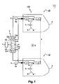
- FIG. 1 corresponds to a schematic representation of means lighting 100 integrating two optical sensors of an imaging system stereoscopic view of an obstacle detection device in accordance with a preferred embodiment of the invention.
- the stereoscopic imaging system is equipped with two sensors optics 1, 1 'such as cameras, connected to a processing unit of images 2 comprising a computer 21 for stereoscopy.
- Each camera 1, 1 realizes instantaneous snapshots and successive stages of the road scene unfolding in front of the vehicle. She then transmits these shots, or images, to means for example software that is a means of fine-tuning images between them inserted in the image processing unit 2 and for example split into two elements 22a, 22b.
- the images thus recaled are transmitted to the computer 21 which calculates the position of objects in the field of view and evaluates their relative movement with respect to the trajectory of the vehicle.
- control means 3 can also be associated with the function of lighting or signaling, for example to means of automatic switching of lamps.
- the lighting means 100 comprise means left lighting 10 and right lighting means 10 'which are by example of projectors with a DBL turn function.
- Each projector 10, 10 ' is conventionally provided with an optic 4, 4' (closing window of the projector and possibly other role plays optical lens) and a light source 5, 5 'mounted on a movable reflector 6, 6 'of the projector 10, 10'.
- One of the cameras called left camera 1 is secured to the reflector left mobile 6 and the other camera called right camera 1 'is attached to the right movable reflector 6 '.
- the cameras 1, 1 ' are mounted directly on the reflectors 6, 6 '.
- the projectors 10, 10 ' can be cleaned identically at the windshield, thanks to headlamp washers (not shown). Thus, left and right camera lenses 1, 1 'are not disturbed the possible soiling on the optics 4, 4 '.
- the obstacle detection device can be optimized, for example for a detection distance of less than or equal to thirty meters.
- Cameras 1, 1 ' are not directly linked mechanically between them in a monolithic structure. Stereoscopic imaging assume parallelism of vertical and horizontal orientation of both cameras 1, 1 'provided by mechanical synchronization means automatically create a virtual link between the left cameras and right 1, 1 '.
- the automatic mechanical synchronization means of the cameras include means for managing vertical pitch 9 and managing the horizontal setting of the cameras 23 which are associated with the settings the vertical orientation and the horizontal orientation of the projectors
- the left and right cameras 1, 1 ' will keep a field almost constant vision, conducive to simplifications of treatment of data and gains in response time and without redundancy of means.
- Each reflector 6, 6 ' is actuated by a motor system 7, 7' associated with a rotation device 8, 8 'of the ball-and-socket type. Also, the reflectors 6, 6 'are rotatable in the horizontal plane P and in the vertical plane (represented by the Z axis in FIG. 1) and each camera 1, 1 'follows the movements of the associated reflector 6, 6 '.
- the vertical pitch management means 9 for example split in two elements 9a, 9b, are conventional management means of the control of the reflectors 6, 6 'of the projectors DBL 10, 10'. These means 9 send to the motor systems 7, 7 'set signals horizontal angular displacements to be subjected to the right and left 6, 6 '.
- the image processing unit 2 comprises means, for example software, management of the horizontal setting 23 of the left and right cameras 1, 1 '. These means 23 are for example split into two elements 23a, 23b. Each element 23a, 23b is connected and drives an engine system separate 7, 7 'respectively by delivering to it setpoint signals appropriate.
- the horizontal setting means 23 may comprise microcomputers that determine the gap between a measured horizon line and the set skyline to bring it back.
- the measured horizon line is the horizon line determined for the road scene considered.
- the target horizon line is a line predetermined horizon during an initial adjustment stage of the headlamps 10, 10 '.
- the target horizon line is determined by the same as the measured horizon, but under ideal initials, for example when putting into circulation the vehicle or during a routine vehicle check.
- This set line is determined by a professional, for a vehicle whose base is flat.
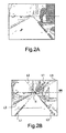
- FIGS. 2A and 2B show, respectively, a natural image and a processed image of an example of a road scene is drop down in front of a vehicle.
- FIG. 2A represents an image taken from the left camera 1 and called natural image, as opposed to the processed image shown on the Figure 2B, this in a classic case of relatively flat road.
- the figure 2B shows the same road scene as image 2A, but after treatment by the associated element 23a means for managing the horizontal setting 23.
- At least two of the natural images of the road scene taken by the left camera 1 are transmitted to the associated element 23a means of 23. These images can be two images successive. This last element 23a makes a comparison between these two natural images.
- This comparison is a subtraction of one of the images by report to the other.
- This subtraction removes the constant areas, that is, the areas that are identical on the first and on the second images.
- the image obtained by subtracting the two images natural resources makes it possible to show the zones that have moved, that is to say the areas and all items related to the speed of the vehicle.
- Element 23a then performs a thresholding of the image obtained by substraction. This thresholding consists of removing all the gray from the image and replace them with whites or blacks, depending on the grayscale initial. The processed image of FIG. 2B is then obtained.
- a single image is processed by means of a mathematical transform applied to each pixel of the image or to sets of pixels in the image.
- This mathematical transform can be, for example, the Hoegh transform.
- the processed image resulting from the image processing (s) is studied to search for leaking lines and points of convergence these fleeting lines. These fleeting lines meet on the horizon. We thus determines what is the measured horizon of the road scene, that is to say the actual horizon for the situation in which the vehicle is located, at the moment considered.
- the lines L1, L2 and L3 are referenced the processed image. These fleeting lines meet in a point of horizon H. On deduces, from this point H, the location of the horizon line of HC setpoint, which is horizontal and which passes through this point H.
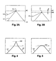
- Figure 3A represents the same road scene as that of the Figure 2B but in a schematic representation. This figure 3A is not an image actually obtained during image processing. It's a figure only intended to better understand the invention.
- This figure 3A shows the important elements noted in the image of Figure 2B and, in particular, the different lines allowing to apply the continuation of the process of the invention. These lines are the leaking lines L1, L2 and L3 that intersect at point of intersection H. Through this point H, pass the measured horizon line HM.
- Element 23a makes it possible to compare the measured horizon line HM with the predetermined HC target horizon line.
- the set line HC and the measured line HM are combined. It can be deduced that the setting of the left projector is correct and that no correction of the orientation of this projector is necessary.
- the deposit line is determined to be located on one of the frame lines of the camera. So the gap E is calculated in number of raster lines.
- the information relating to the gap E is then supplied to the system of motors 7 which changes the vertical orientation of the projector 10 by raising it until the measured horizon line is confused with the line of setpoint. In other words, the inclination of the projector 10 and, therefore, of the light source 5, until the gap E tends to zero.
- the difference E is converted into a control signal of the motor system 7 to return to the set point of the horizon line.
- checking the positioning of the skyline measured on the set line is done using the left camera 6, that is to say by visualizing, on images taken instantly by the camera, the two HM and HC skylines.
- FIG 4 there is shown the particular case of a road in the background of valley. This case is represented in a schematized way, as were the previous examples of FIGS. 3A and 3B.
- the particular case schematized in Figure 4 is the case where the vehicle is in the bottom of a valley and where he is getting ready to climb a hill or a mountain.
- the part, which is below the dotted line C shows the road which lies in the bottom of the valley and which forms the leaking lines L4 and L5.
- the leaking lines L4 and L5 are cut, that is to say that they form a non-flat angle with the lines leaking initials.
- This cut C of leaking lines represents the place where the road begins to climb, that is, where the road has a slope compared to the part of the road that was flat in the bottom of the valley.
- two lines of horizon measured A line with the part of leaking located under the cut C and a line HM with the part of leaking located above the cutoff C. It is this last horizon, that is to say, that measured in the part superior image, which is taken into account in the case of a background of valley.
- This measured HM horizon is determined exactly same way as in the case of Figures 2 and 3.
- FIG. 5 is a schematic representation of the case particular of a vehicle at the top of a hill.
- the vehicle is on a hill and is ready to approach a flat road or a road downhill.
- the leaking lines L6 and L7 of the coast road intersect at the C line.
- This measured HM horizon is determined exactly same way as in the case of Figures 2 and 3.
- FIG. 6 shows a particular situation in which can be a vehicle.
- This situation is one where another vehicle and in particular a relatively large vehicle of the type truck, is driving on the road in front of the vehicle in question.
- Figure 6 shows the image obtained after treatment, in such a situation.
- the truck has hindered the taking of images of the road scene.
- the image obtained after treatment includes only part of the lines leaking L8 and L9.
- this part of the leaking lines detected, located between the truck and the vehicle it is possible to extrapolate following these fleeting lines.
- These extrapolated lines are represented in dotted in Figure 6, in the extension of the leaking lines L8 and L9.
- the measured horizon line HM can then be determined from these extrapolated leaking lines, in the same way as previously explained. This achieves a realistic correction of the image.
- This extrapolation in the event of an obstacle can lead to reducing the accuracy of the projector's orientation.
- a light source locatable on a video image This process consists, in fact, in issuing a specific luminous pattern not visible to the naked eye for the driver, but detectable by the camera either by its high brightness or thanks to a particular modulation like a blink.
- This light source can be, for example, a source of laser beams.
- the source luminaire is mounted in the projector so as to be movable reflector. It emits a beam which contributes to the restitution of leaking lines.
- the orientation of the projector is adjusted function of an information taking into account, on the one hand, the gap E and, on the other hand, on the other hand, the shape of the specific design.
- This information can be obtained by geometric calculations or knowledge of a neural network having made his apprenticeship during sequences of visibility without obstacle.
- the specific drawing can be, in particular, a bundle of lines parallel, for example, by a diffraction grating or a conjugation of lenses. This case can be implemented in the presence of a obstacle or in difficult traffic conditions such as traffic dense.
- each line generator light is attached to the end of the associated reflector which is opposite to the camera.
- Each light line generator is directed forward close to the vehicle and oriented so that the lines of light are placed between the leaking lines L10 and L11.
- FIG. 7 shows an example of a processed image of a road scene, in the case where parallel lines are projected according to the above variant.
- This figure 7 shows the lines leaking L10 and L11 as well as the projected lines LP which, on the processed image, form elusive segments that contribute, with fleeting lines L10 and L11, to determine the measured horizon line.
- the precision of the determination of the horizon line is proportional to the number of lines parallel.
- these parallel lines are emitted to be close to the vehicle, for example a few meters in front of the vehicle, so not to be affected by the presence of previous vehicles.
- the image processing unit 2 gathering the means 21, 22, 23 may be partially or fully integrated into the vehicle or added to the vehicle.
- the invention applies equally well to fire projectors road, to FBL projectors, or to signal planners located for example at the rear of the vehicle.
Abstract
Description
- détection de piéton de toute taille, d'un véhicule dangereux,
- détection d'un animal traversant la route,
- détection de l'arrivée brutale d'un voiture venant à l'arrière et apparaissant dans la zone de sécurité par exemple pour un déclenchement des « warning » et dans le cadre de l'ARS (Advance Rear Lighting System en anglais),
- détection d'un objet (véhicule, poteau) pendant une manoeuvre (créneau, sortie de garage) afin de fournir une assistance,
- détection de pluie, brouillard, neige par la mesure de la transmission de l'atmosphère.
- des moyens de gestion du mouvement du véhicule, par exemple des actionneurs pour actions sur les freins ou sur la direction,
- des moyens pour l'anticipation de virage,
- des moyens de gestion de la position du véhicule par rapport aux bandes blanches soit pour assurer le suivi de voie par exemple sur autoroute.
- des moyens d'avertissement sonores du conducteur et/ou de l'extérieur, en cas de risque potentiel,
- des moyens d'avertissement visuels (afficheurs) du conducteur et/ou de l'extérieur, en cas de risque potentiel,
- des moyens de réduire l'éblouissement potentiel du conducteur,
- des moyens de commande d'un élément de sécurité active interne et/ou externe, tel qu'un airbag,
- des moyens de commutation automatique de lampes, par exemple dans le cadre de l'AFS (Adaptive Front Lighting System en anglais), dans le cadre d'un allumage jour-nuit, dans le cadre d'une commutation entre un faisceau code et un faisceau route, ou encore dans le cadre d'un éclairage optimisé pour éviter l'éblouissement des autres conducteurs.
- la figure 1 correspond à une représentation schématique de moyens d'éclairage de véhicule automobile intégrant deux capteurs optiques d'un système d'imagerie stéréoscopique d'un dispositif de détection d'obstacle conformément à un mode de réalisation préféré de l'invention ;
- la figure 2A représente un exemple d'image d'une scène de route située devant un véhicule dans un cas classique de route relativement plate ;
- la figure 2B représente l'image de la figure 2A après avoir été traitée ;
- les figures 3A et 3B représentent schématiquement deux cas d'éclairage sur la route des figures 2A et 2B ;
- la figure 4 montre une image traitée d'une scène de route dans le cas où un véhicule se trouve sur une route en fond de vallée ;
- la figure 5 montre une image traitée d'une scène de route traitée dans le cas où le véhicule se trouve au sommet d'une côte ;
- la figure 6 montre une image traitée d'une scène de route dans le cas où la prise de l'image a été gênée ;
- la figure 7 représente une image traitée d'une scène de route, dans le cas où sont projetées des lignes parallèles.
- des moyens de gestion du mouvement du véhicule,
- des moyens pour l'anticipation de virage et des moyens de gestion de la position du véhicule par rapport aux bandes blanches,
- des moyens d'avertissement sonore,
- des moyens de commande d'un élément de sécurité active interne (pour les conducteurs et/ou passagers) et/ou externe (pour l'obstacle piéton par exemple),
- et des moyens d'avertissement visuels.
- des moyens de traitement d'images aptes à effectuer un traitement sur une ou sur deux images successives transmises par la caméra gauche ou droite 1, 1',
- des moyens de détermination des lignes d'horizon d'une image résultant du traitement d'image(s), par exemple à l'aide des moyens de détermination de lignes fuyantes (ou de segments de lignes fuyantes de taille suffisante pour être extrapolé),
- et des moyens de détermination de la coïncidence de la ligne d'horizon avec une ligne de consigne qui est la même pour les deux caméras.
Claims (15)
- Dispositif de détection d'obstacle comportant un système d'imagerie stéréoscopique incluant deux capteurs optiques (1, 1') caractérisé en ce que les capteurs sont intégrés dans des moyens d'éclairage (100, 10, 10') et/ou de signalisation pour véhicule automobile.
- Dispositif de détection d'obstacle selon la revendication 1 caractérisé en ce que la distance entre les capteurs optiques (1, 1') est choisie supérieure à 50 cm et de préférence supérieure ou égale à 1 mètre.
- Dispositif de détection d'obstacle selon la revendication 1 ou 2 caractérisé en ce que les capteurs (1, 1') sont liés mécaniquement par une liaison virtuelle comprenant des moyens de synchronisation mécaniques (9, 23) et de préférence automatiques.
- Dispositif de détection d'obstacle selon l'une des revendications 1 à 3 caractérisé en ce que l'un des capteurs optiques (1) est intégré dans des moyens d'éclairage (10) et/ou de signalisation gauches et l'autre des capteurs optiques (1') est intégré dans des moyens d'éclairage (10') et/ou de signalisation droits.
- Dispositif de détection d'obstacle selon l'une des revendications 1 à 4 caractérisé en ce que l'un des capteurs optiques (1) est solidaire d'un réflecteur mobile (6) des moyens d'éclairage gauches (10) et l'autre des capteurs optiques (1') est solidaire d'un réflecteur mobile (6) des moyens d'éclairage droits (10').
- Dispositif de détection d'obstacle selon l'une des revendications 1 à 5 caractérisé en ce que le dispositif comporte des moyens de gestion du calage vertical (9) des capteurs optiques (1, 1'), de préférence automatiques.
- Dispositif de détection d'obstacle selon la revendication 6 caractérisé en ce que, lorsque les capteurs (1, 1') sont solidaires de réflecteurs mobiles en rotation dans le plan horizontal, des moyens de commande de la rotation (7, 7') dans le plan horizontal desdits réflecteurs sont pilotés par lesdits moyens de gestion du calage vertical (9).
- Dispositif de détection d'obstacle selon l'une des revendications 1 à 7 caractérisé en ce qu'il comprend des moyens de correction d'images (22).
- Dispositif de détection d'obstacle selon l'une des revendications 1 à 8 caractérisé en ce qu'il comprend des moyens de gestion du calage horizontal (23) des capteurs optiques (1, 1'), de préférence automatiques.
- Dispositif de détection d'obstacle selon la revendication 9 caractérisé en ce que les moyens de gestion du calage horizontal (23) comportent des moyens de détermination des lignes d'horizon d'images de scènes de route prises par les capteurs et des moyens de détermination de la coïncidence desdites lignes d'horizon avec une ligne de consigne prédéterminée.
- Dispositif de détection d'obstacle selon l'une des revendications 9 ou 10 caractérisé en ce que les moyens de détermination des lignes d'horizon comprennent des moyens de recherche d'au moins des segments extrapolables de lignes fuyantes des images et, de préférence, deux générateurs de lignes lumineuses, chacun associé à l'un distinct des capteurs (1, 1'), et orientés de façon à ce que les lignes lumineuses soient placées entre les lignes fuyantes des images.
- Dispositif de détection d'obstacle selon l'une des revendications 9 à 11 caractérisé en ce que, lorsque les capteurs (1, 1') sont solidaires de réflecteurs mobiles en rotation dans le plan vertical, des moyens de commande de la rotation (7, 7') dans le plan vertical desdits réflecteurs (6, 6') sont pilotés par lesdits moyens de gestion du calage horizontal (23).
- Dispositif de détection d'obstacle selon l'une des revendications 1 à 12 caractérisé en ce que les capteurs optiques (1, 1') sont choisis parmi des caméras et des systèmes à laser.
- Dispositif de détection d'obstacle selon l'une des revendications 1 à 13 caractérisé en ce qu'il comprend des moyens de commande (3) de l'un ou plusieurs des moyens suivants : des moyens de gestion du mouvement du véhicule, des moyens pour l'anticipation de virage et des moyens de gestion de la position du véhicule par rapport aux bandes blanches.
- Dispositif de détection d'obstacle selon l'une des revendications 1 à 14 caractérisé en ce qu'il comprend des moyens de commande (3) de l'un ou plusieurs des moyens suivants des moyens d'avertissement sonore, des moyens d'avertissement visuels, des moyens de réduction de l'éblouissement potentiel du conducteur, des moyens de commande d'un élément de sécurité active interne et/ou externe et des moyens de commutation automatique de lampes.
Applications Claiming Priority (2)
| Application Number | Priority Date | Filing Date | Title |
|---|---|---|---|
| FR0310718A FR2859860B1 (fr) | 2003-09-11 | 2003-09-11 | Dispositif de detection d'obstacle comportant un systeme d'imagerie stereoscopique incluant deux capteurs optiques |
| FR0310718 | 2003-09-11 |
Publications (1)
| Publication Number | Publication Date |
|---|---|
| EP1515293A1 true EP1515293A1 (fr) | 2005-03-16 |
Family
ID=34130797
Family Applications (1)
| Application Number | Title | Priority Date | Filing Date |
|---|---|---|---|
| EP04292151A Ceased EP1515293A1 (fr) | 2003-09-11 | 2004-09-07 | Dispositif de détection d'obstacle comportant un système d'imagerie stéréoscopique incluant deux capteurs optiques |
Country Status (2)
| Country | Link |
|---|---|
| EP (1) | EP1515293A1 (fr) |
| FR (1) | FR2859860B1 (fr) |
Cited By (16)
| Publication number | Priority date | Publication date | Assignee | Title |
|---|---|---|---|---|
| EP1724153A1 (fr) * | 2005-05-20 | 2006-11-22 | Valeo Vision | Dispositif de détection d'obstacles comportant un système d'imagerie pour véhicule automobile |
| EP1757485A1 (fr) * | 2005-08-24 | 2007-02-28 | Dr.Ing. h.c.F. Porsche Aktiengesellschaft | Procédé de commande de la portée de phares de véhicule |
| WO2007057274A1 (fr) * | 2005-11-18 | 2007-05-24 | Robert Bosch Gmbh | Module de phare a capteur de lumiere et de pluie integre |
| DE102006016071A1 (de) * | 2006-04-04 | 2007-10-18 | Dr.Ing.H.C. F. Porsche Ag | Steuerung der Leuchtweite von Scheinwerfern eines Kraftfahrzeuges |
| WO2014043240A1 (fr) * | 2012-09-11 | 2014-03-20 | Gentex Corporation | Système et procédé de détection d'un imageur bloqué |
| WO2015015494A1 (fr) | 2013-07-31 | 2015-02-05 | Katz Elen Josef | Système et procédé pour l'identification et l'évitement d'obstacles |
| CN105599667A (zh) * | 2014-11-19 | 2016-05-25 | 曼卡车和巴士股份公司 | 在车辆上,特别是在商用车辆上的大灯模块的组件 |
| CN105678221A (zh) * | 2015-12-29 | 2016-06-15 | 大连楼兰科技股份有限公司 | 一种雨雪天气的行人检测方法及系统 |
| CN107176098A (zh) * | 2017-07-10 | 2017-09-19 | 辽宁工业大学 | 一种内轮差盲区自动监测预警装置及控制方法 |
| EP2294380B1 (fr) * | 2008-07-03 | 2019-07-10 | ADC Automotive Distance Control Systems GmbH | Procédé de détection du désajustement d'un projecteur de véhicule à l'aide d'un appareil de prise de vue |
| EP3508406A4 (fr) * | 2016-08-31 | 2019-07-10 | Honda Motor Co., Ltd. | Véhicule de type à selle |
| WO2020109235A1 (fr) * | 2018-11-26 | 2020-06-04 | Zkw Group Gmbh | Système de vision pour véhicule avec imageur à étalonnage automatique |
| CN112009524A (zh) * | 2020-07-15 | 2020-12-01 | 北京埃福瑞科技有限公司 | 一种用于有轨电车障碍物检测的系统及方法 |
| CN113242813A (zh) * | 2018-12-12 | 2021-08-10 | 宁波吉利汽车研究开发有限公司 | 用于警告车辆驾驶员在车辆附近有对象的系统和方法 |
| US11104279B2 (en) | 2018-11-26 | 2021-08-31 | Magna Electronics Solutions Gmbh | Vehicle vision system with adaptive reversing light |
| CN115556664A (zh) * | 2022-09-16 | 2023-01-03 | 深圳市欧冶半导体有限公司 | 提升行车安全的智能前照灯冗余方法及系统 |
Citations (8)
| Publication number | Priority date | Publication date | Assignee | Title |
|---|---|---|---|---|
| JPH0840140A (ja) * | 1994-08-02 | 1996-02-13 | Niles Parts Co Ltd | 前照灯制御装置 |
| JP2000318513A (ja) * | 1999-05-17 | 2000-11-21 | Mitsubishi Electric Corp | 車両用障害物検出装置 |
| JP2001158284A (ja) * | 1999-11-30 | 2001-06-12 | Honda Access Corp | 照明装置,カメラ装置,センサー装置などの車両外面部に組み込む組込装置の取付構造 |
| JP2001260778A (ja) * | 2000-03-15 | 2001-09-26 | Auto Network Gijutsu Kenkyusho:Kk | 車両の障害物検知装置 |
| JP2003006620A (ja) * | 2001-06-25 | 2003-01-10 | Nec Corp | ステレオカメラによる障害物の認識方法およびその認識処理装置 |
| DE10131196A1 (de) * | 2001-06-28 | 2003-01-16 | Bosch Gmbh Robert | Vorrichtung zur Detektion von Gegenständen, Personen oder dergleichen |
| WO2003019233A1 (fr) * | 2001-08-20 | 2003-03-06 | Siemens Aktiengesellschaft | Dispositif de detection d'obstacles |
| US20030045984A1 (en) * | 2001-08-31 | 2003-03-06 | Yasutoshi Horii | Vehicle headlamp's optical axis control system |
-
2003
- 2003-09-11 FR FR0310718A patent/FR2859860B1/fr not_active Expired - Fee Related
-
2004
- 2004-09-07 EP EP04292151A patent/EP1515293A1/fr not_active Ceased
Patent Citations (8)
| Publication number | Priority date | Publication date | Assignee | Title |
|---|---|---|---|---|
| JPH0840140A (ja) * | 1994-08-02 | 1996-02-13 | Niles Parts Co Ltd | 前照灯制御装置 |
| JP2000318513A (ja) * | 1999-05-17 | 2000-11-21 | Mitsubishi Electric Corp | 車両用障害物検出装置 |
| JP2001158284A (ja) * | 1999-11-30 | 2001-06-12 | Honda Access Corp | 照明装置,カメラ装置,センサー装置などの車両外面部に組み込む組込装置の取付構造 |
| JP2001260778A (ja) * | 2000-03-15 | 2001-09-26 | Auto Network Gijutsu Kenkyusho:Kk | 車両の障害物検知装置 |
| JP2003006620A (ja) * | 2001-06-25 | 2003-01-10 | Nec Corp | ステレオカメラによる障害物の認識方法およびその認識処理装置 |
| DE10131196A1 (de) * | 2001-06-28 | 2003-01-16 | Bosch Gmbh Robert | Vorrichtung zur Detektion von Gegenständen, Personen oder dergleichen |
| WO2003019233A1 (fr) * | 2001-08-20 | 2003-03-06 | Siemens Aktiengesellschaft | Dispositif de detection d'obstacles |
| US20030045984A1 (en) * | 2001-08-31 | 2003-03-06 | Yasutoshi Horii | Vehicle headlamp's optical axis control system |
Non-Patent Citations (5)
| Title |
|---|
| PATENT ABSTRACTS OF JAPAN vol. 1996, no. 06 28 June 1996 (1996-06-28) * |
| PATENT ABSTRACTS OF JAPAN vol. 2000, no. 14 5 March 2001 (2001-03-05) * |
| PATENT ABSTRACTS OF JAPAN vol. 2000, no. 23 * |
| PATENT ABSTRACTS OF JAPAN vol. 2000, no. 26 1 July 2002 (2002-07-01) * |
| PATENT ABSTRACTS OF JAPAN vol. 2003, no. 05 12 May 2003 (2003-05-12) * |
Cited By (35)
| Publication number | Priority date | Publication date | Assignee | Title |
|---|---|---|---|---|
| FR2885860A1 (fr) * | 2005-05-20 | 2006-11-24 | Valeo Vision Sa | Dispositif de detection d'obstacles comportant un systeme d'imagerie pour vehicule automobile |
| US7693302B2 (en) | 2005-05-20 | 2010-04-06 | Valeo Vision | Device for detecting obstacles comprising an imaging system for motor vehicles |
| EP1724153A1 (fr) * | 2005-05-20 | 2006-11-22 | Valeo Vision | Dispositif de détection d'obstacles comportant un système d'imagerie pour véhicule automobile |
| US7447581B2 (en) | 2005-08-24 | 2008-11-04 | Dr. Ing. H.C. F. Porsche Aktiengesellschaft | Procedure for controlling the light width of a motor vehicle |
| EP1757485A1 (fr) * | 2005-08-24 | 2007-02-28 | Dr.Ing. h.c.F. Porsche Aktiengesellschaft | Procédé de commande de la portée de phares de véhicule |
| JP2009516278A (ja) * | 2005-11-18 | 2009-04-16 | ローベルト ボツシユ ゲゼルシヤフト ミツト ベシユレンクテル ハフツング | 光学式レインセンサが組み込まれているヘッドライトモジュール |
| WO2007057274A1 (fr) * | 2005-11-18 | 2007-05-24 | Robert Bosch Gmbh | Module de phare a capteur de lumiere et de pluie integre |
| JP4718614B2 (ja) * | 2005-11-18 | 2011-07-06 | ローベルト ボツシユ ゲゼルシヤフト ミツト ベシユレンクテル ハフツング | 光学式レインセンサが組み込まれているヘッドライトモジュール |
| DE102006016071A1 (de) * | 2006-04-04 | 2007-10-18 | Dr.Ing.H.C. F. Porsche Ag | Steuerung der Leuchtweite von Scheinwerfern eines Kraftfahrzeuges |
| US7930083B2 (en) | 2006-04-04 | 2011-04-19 | Dr. Ing. H.C. F. Porsche Aktiengesellschaft | Method of controlling beam projection of headlights of a motor vehicle |
| DE102006016071B4 (de) * | 2006-04-04 | 2021-03-25 | Dr. Ing. H.C. F. Porsche Aktiengesellschaft | Steuerung der Leuchtweite von Scheinwerfern eines Kraftfahrzeuges |
| EP2294380B1 (fr) * | 2008-07-03 | 2019-07-10 | ADC Automotive Distance Control Systems GmbH | Procédé de détection du désajustement d'un projecteur de véhicule à l'aide d'un appareil de prise de vue |
| WO2014043240A1 (fr) * | 2012-09-11 | 2014-03-20 | Gentex Corporation | Système et procédé de détection d'un imageur bloqué |
| US9199574B2 (en) | 2012-09-11 | 2015-12-01 | Gentex Corporation | System and method for detecting a blocked imager |
| EP3027482A4 (fr) * | 2013-07-31 | 2017-07-12 | Rail Vision Ltd | Système et procédé pour l'identification et l'évitement d'obstacles |
| US10654499B2 (en) | 2013-07-31 | 2020-05-19 | Rail Vision Ltd. | System and method for utilizing an infra-red sensor by a moving train |
| WO2015015494A1 (fr) | 2013-07-31 | 2015-02-05 | Katz Elen Josef | Système et procédé pour l'identification et l'évitement d'obstacles |
| CN108446643A (zh) * | 2013-07-31 | 2018-08-24 | 铁路视像有限公司 | 用于铁路障碍物识别的方法 |
| CN105599667A (zh) * | 2014-11-19 | 2016-05-25 | 曼卡车和巴士股份公司 | 在车辆上,特别是在商用车辆上的大灯模块的组件 |
| EP3023299A3 (fr) * | 2014-11-19 | 2016-12-07 | MAN Truck & Bus AG | Systeme d'un module de phare sur un vehicule, notamment sur un vehicule utilitaire |
| RU2700315C2 (ru) * | 2014-11-19 | 2019-09-16 | Ман Трак Унд Бас Аг | Система модуля фары на транспортном средстве, в частности на транспортном средстве промышленного назначения |
| CN105678221A (zh) * | 2015-12-29 | 2016-06-15 | 大连楼兰科技股份有限公司 | 一种雨雪天气的行人检测方法及系统 |
| EP3508406A4 (fr) * | 2016-08-31 | 2019-07-10 | Honda Motor Co., Ltd. | Véhicule de type à selle |
| US11279427B2 (en) | 2016-08-31 | 2022-03-22 | Honda Motor Co., Ltd. | Saddle-type vehicle |
| CN107176098A (zh) * | 2017-07-10 | 2017-09-19 | 辽宁工业大学 | 一种内轮差盲区自动监测预警装置及控制方法 |
| CN107176098B (zh) * | 2017-07-10 | 2023-07-07 | 辽宁工业大学 | 一种内轮差盲区自动监测预警装置及控制方法 |
| WO2020109235A1 (fr) * | 2018-11-26 | 2020-06-04 | Zkw Group Gmbh | Système de vision pour véhicule avec imageur à étalonnage automatique |
| CN113286726A (zh) * | 2018-11-26 | 2021-08-20 | Zkw集团有限责任公司 | 具有自校准成像器的车辆视觉系统 |
| US11104279B2 (en) | 2018-11-26 | 2021-08-31 | Magna Electronics Solutions Gmbh | Vehicle vision system with adaptive reversing light |
| US11667231B2 (en) | 2018-11-26 | 2023-06-06 | Magna Electronics Solutions Gmbh | Vehicle vision system with self-calibrating imager |
| CN113242813A (zh) * | 2018-12-12 | 2021-08-10 | 宁波吉利汽车研究开发有限公司 | 用于警告车辆驾驶员在车辆附近有对象的系统和方法 |
| CN112009524A (zh) * | 2020-07-15 | 2020-12-01 | 北京埃福瑞科技有限公司 | 一种用于有轨电车障碍物检测的系统及方法 |
| CN112009524B (zh) * | 2020-07-15 | 2022-06-07 | 北京埃福瑞科技有限公司 | 一种用于有轨电车障碍物检测的系统及方法 |
| CN115556664A (zh) * | 2022-09-16 | 2023-01-03 | 深圳市欧冶半导体有限公司 | 提升行车安全的智能前照灯冗余方法及系统 |
| CN115556664B (zh) * | 2022-09-16 | 2023-07-21 | 深圳市欧冶半导体有限公司 | 提升行车安全的智能前照灯冗余方法及系统 |
Also Published As
| Publication number | Publication date |
|---|---|
| FR2859860A1 (fr) | 2005-03-18 |
| FR2859860B1 (fr) | 2006-02-17 |
Similar Documents
| Publication | Publication Date | Title |
|---|---|---|
| EP1437258B1 (fr) | Système de commande de l'orientation en site d'un projecteur de véhicule et procédé de mise en oeuvre | |
| EP1437259B1 (fr) | Système de commande de l'orientation en site d'un projecteur de véhicule et procédé de mise en oeuvre | |
| EP1515293A1 (fr) | Dispositif de détection d'obstacle comportant un système d'imagerie stéréoscopique incluant deux capteurs optiques | |
| EP1553429B1 (fr) | Système et procédé de détection de conditions de circulation pour véhicule automobile | |
| CN104024827B (zh) | 图像处理装置、图像捕捉方法和车辆 | |
| EP1415856B1 (fr) | Procédé de commande des faisceaux lumineux émis par un dispositif d'éclairage d'un véhicule et système de mise en oeuvre de ce procédé | |
| EP1724153B1 (fr) | Dispositif d'éclairage ou de signalisation de véhicule automobile | |
| EP0455524B1 (fr) | Système d'éclairage et de visualisation pour véhicules | |
| CN111527016B (zh) | 用于控制自动驾驶载具的图像捕获设备遇到的光的程度的方法和系统 | |
| CN102447911A (zh) | 图像获取单元、其方法以及相关控制单元 | |
| FR2759043A1 (fr) | Installation pour regler la portee des projecteurs d'un vehicule | |
| EP1920970B1 (fr) | Système de correction dynamique de l'orientation d'une source lumineuse d'un véhicule et procédé associé | |
| EP0642950B1 (fr) | Dispositif de commande automatique de l'orientation des projecteurs d'un véhicule automobile en fonction des variations d'assiette de celui-ci | |
| FR2785434A1 (fr) | Procede d'aide a la conduite d'un vehicule et dispositif de mise en oeuvre | |
| EP2754950A1 (fr) | Torche d'éclairage pour véhicule automobile | |
| FR3055431B1 (fr) | Dispositif de projection d'une image pixelisee | |
| FR2705293A1 (fr) | Système d'aide à la vision dans un véhicule automobile. | |
| EP3074922B1 (fr) | Système et procédé de formation d'images nocturnes pour un véhicule automobile | |
| EP3860878A1 (fr) | Procédé de pilotage de modules de projection de faisceaux de lumiere pixellise pour vehicule | |
| FR3019266A1 (fr) | Systeme d'eclairage pour vehicule avec reglage automatise | |
| WO2022157339A1 (fr) | Système d'éclairage de véhicule automobile muni d'un module lumineux apte à émettre un faisceau lumineux pixélisé | |
| WO2022180253A1 (fr) | Procédé de contrôle d'un système d'éclairage d'un véhicule automobile | |
| WO2006048559A1 (fr) | Systeme de feux de croisement pour vehicules automobiles | |
| FR3058690B1 (fr) | Systeme d'eclairage assiste pour vehicule et procede de formation d'une image hybride | |
| FR3068667A1 (fr) | Procede d’activation automatique d’une fonction d’un vehicule automobile |
Legal Events
| Date | Code | Title | Description |
|---|---|---|---|
| PUAI | Public reference made under article 153(3) epc to a published international application that has entered the european phase |
Free format text: ORIGINAL CODE: 0009012 |
|
| AK | Designated contracting states |
Kind code of ref document: A1 Designated state(s): AT BE BG CH CY CZ DE DK EE ES FI FR GB GR HU IE IT LI LU MC NL PL PT RO SE SI SK TR |
|
| AX | Request for extension of the european patent |
Extension state: AL HR LT LV MK |
|
| 17P | Request for examination filed |
Effective date: 20050725 |
|
| AKX | Designation fees paid |
Designated state(s): AT BE BG CH CY CZ DE DK EE ES FI FR GB GR HU IE IT LI LU MC NL PL PT RO SE SI SK TR |
|
| 17Q | First examination report despatched |
Effective date: 20111216 |
|
| STAA | Information on the status of an ep patent application or granted ep patent |
Free format text: STATUS: THE APPLICATION HAS BEEN REFUSED |
|
| 18R | Application refused |
Effective date: 20180622 |
|
| RIC1 | Information provided on ipc code assigned before grant |
Ipc: G08G 1/16 20060101AFI20050117BHEP Ipc: B61L 23/04 20060101ALI20050117BHEP Ipc: G01S 13/93 20060101ALI20050117BHEP Ipc: B60Q 1/08 20060101ALI20050117BHEP Ipc: G06T 7/00 20170101ALI20050117BHEP |