EP1515203A1 - Procédé de fabrication et de montage de contacts éléctriques pour organes de commande de faibles dimensions, notamment pour l'horlogerie - Google Patents
Procédé de fabrication et de montage de contacts éléctriques pour organes de commande de faibles dimensions, notamment pour l'horlogerie Download PDFInfo
- Publication number
- EP1515203A1 EP1515203A1 EP03020320A EP03020320A EP1515203A1 EP 1515203 A1 EP1515203 A1 EP 1515203A1 EP 03020320 A EP03020320 A EP 03020320A EP 03020320 A EP03020320 A EP 03020320A EP 1515203 A1 EP1515203 A1 EP 1515203A1
- Authority
- EP
- European Patent Office
- Prior art keywords
- contact blades
- electrical contact
- electrical
- blades
- crown
- Prior art date
- Legal status (The legal status is an assumption and is not a legal conclusion. Google has not performed a legal analysis and makes no representation as to the accuracy of the status listed.)
- Granted
Links
- 238000000034 method Methods 0.000 title claims abstract description 24
- 238000004519 manufacturing process Methods 0.000 title claims description 20
- 239000004020 conductor Substances 0.000 claims abstract description 7
- 230000008569 process Effects 0.000 claims description 5
- 238000004026 adhesive bonding Methods 0.000 claims description 2
- 238000005520 cutting process Methods 0.000 claims description 2
- 238000002360 preparation method Methods 0.000 claims description 2
- 238000003466 welding Methods 0.000 claims description 2
- 239000011810 insulating material Substances 0.000 claims 1
- 238000007493 shaping process Methods 0.000 abstract 1
- 230000009471 action Effects 0.000 description 4
- 230000007935 neutral effect Effects 0.000 description 4
- 210000000056 organ Anatomy 0.000 description 4
- 239000011324 bead Substances 0.000 description 3
- RYGMFSIKBFXOCR-UHFFFAOYSA-N Copper Chemical compound [Cu] RYGMFSIKBFXOCR-UHFFFAOYSA-N 0.000 description 2
- 229910052802 copper Inorganic materials 0.000 description 2
- 239000010949 copper Substances 0.000 description 2
- 238000001514 detection method Methods 0.000 description 2
- 239000012777 electrically insulating material Substances 0.000 description 2
- 239000000463 material Substances 0.000 description 2
- 239000002184 metal Substances 0.000 description 2
- 229910052751 metal Inorganic materials 0.000 description 2
- 229910000831 Steel Inorganic materials 0.000 description 1
- 230000001419 dependent effect Effects 0.000 description 1
- 238000006073 displacement reaction Methods 0.000 description 1
- 229940082150 encore Drugs 0.000 description 1
- 238000003780 insertion Methods 0.000 description 1
- 230000037431 insertion Effects 0.000 description 1
- 238000009413 insulation Methods 0.000 description 1
- 230000000873 masking effect Effects 0.000 description 1
- 238000012986 modification Methods 0.000 description 1
- 230000004048 modification Effects 0.000 description 1
- 238000000465 moulding Methods 0.000 description 1
- 229920001690 polydopamine Polymers 0.000 description 1
- 230000000284 resting effect Effects 0.000 description 1
- 238000007789 sealing Methods 0.000 description 1
- 239000010959 steel Substances 0.000 description 1
- 239000002436 steel type Substances 0.000 description 1
Images




Classifications
-
- G—PHYSICS
- G04—HOROLOGY
- G04G—ELECTRONIC TIME-PIECES
- G04G17/00—Structural details; Housings
- G04G17/02—Component assemblies
-
- H—ELECTRICITY
- H01—ELECTRIC ELEMENTS
- H01H—ELECTRIC SWITCHES; RELAYS; SELECTORS; EMERGENCY PROTECTIVE DEVICES
- H01H25/00—Switches with compound movement of handle or other operating part
- H01H25/06—Operating part movable both angularly and rectilinearly, the rectilinear movement being along the axis of angular movement
-
- G—PHYSICS
- G04—HOROLOGY
- G04C—ELECTROMECHANICAL CLOCKS OR WATCHES
- G04C3/00—Electromechanical clocks or watches independent of other time-pieces and in which the movement is maintained by electric means
- G04C3/001—Electromechanical switches for setting or display
-
- G—PHYSICS
- G04—HOROLOGY
- G04C—ELECTROMECHANICAL CLOCKS OR WATCHES
- G04C3/00—Electromechanical clocks or watches independent of other time-pieces and in which the movement is maintained by electric means
- G04C3/001—Electromechanical switches for setting or display
- G04C3/007—Electromechanical contact-making and breaking devices acting as pulse generators for setting
-
- H—ELECTRICITY
- H01—ELECTRIC ELEMENTS
- H01H—ELECTRIC SWITCHES; RELAYS; SELECTORS; EMERGENCY PROTECTIVE DEVICES
- H01H11/00—Apparatus or processes specially adapted for the manufacture of electric switches
- H01H11/0056—Apparatus or processes specially adapted for the manufacture of electric switches comprising a successive blank-stamping, insert-moulding and severing operation
-
- H—ELECTRICITY
- H01—ELECTRIC ELEMENTS
- H01R—ELECTRICALLY-CONDUCTIVE CONNECTIONS; STRUCTURAL ASSOCIATIONS OF A PLURALITY OF MUTUALLY-INSULATED ELECTRICAL CONNECTING ELEMENTS; COUPLING DEVICES; CURRENT COLLECTORS
- H01R43/00—Apparatus or processes specially adapted for manufacturing, assembling, maintaining, or repairing of line connectors or current collectors or for joining electric conductors
- H01R43/16—Apparatus or processes specially adapted for manufacturing, assembling, maintaining, or repairing of line connectors or current collectors or for joining electric conductors for manufacturing contact members, e.g. by punching and by bending
-
- H—ELECTRICITY
- H01—ELECTRIC ELEMENTS
- H01H—ELECTRIC SWITCHES; RELAYS; SELECTORS; EMERGENCY PROTECTIVE DEVICES
- H01H15/00—Switches having rectilinearly-movable operating part or parts adapted for actuation in opposite directions, e.g. slide switch
- H01H15/02—Details
- H01H15/06—Movable parts; Contacts mounted thereon
- H01H15/10—Operating parts
- H01H15/102—Operating parts comprising cam devices
-
- H—ELECTRICITY
- H01—ELECTRIC ELEMENTS
- H01H—ELECTRIC SWITCHES; RELAYS; SELECTORS; EMERGENCY PROTECTIVE DEVICES
- H01H19/00—Switches operated by an operating part which is rotatable about a longitudinal axis thereof and which is acted upon directly by a solid body external to the switch, e.g. by a hand
- H01H19/005—Electromechanical pulse generators
-
- H—ELECTRICITY
- H01—ELECTRIC ELEMENTS
- H01H—ELECTRIC SWITCHES; RELAYS; SELECTORS; EMERGENCY PROTECTIVE DEVICES
- H01H2300/00—Orthogonal indexing scheme relating to electric switches, relays, selectors or emergency protective devices covered by H01H
- H01H2300/016—Application timepiece
-
- Y—GENERAL TAGGING OF NEW TECHNOLOGICAL DEVELOPMENTS; GENERAL TAGGING OF CROSS-SECTIONAL TECHNOLOGIES SPANNING OVER SEVERAL SECTIONS OF THE IPC; TECHNICAL SUBJECTS COVERED BY FORMER USPC CROSS-REFERENCE ART COLLECTIONS [XRACs] AND DIGESTS
- Y10—TECHNICAL SUBJECTS COVERED BY FORMER USPC
- Y10T—TECHNICAL SUBJECTS COVERED BY FORMER US CLASSIFICATION
- Y10T29/00—Metal working
- Y10T29/49—Method of mechanical manufacture
- Y10T29/49002—Electrical device making
-
- Y—GENERAL TAGGING OF NEW TECHNOLOGICAL DEVELOPMENTS; GENERAL TAGGING OF CROSS-SECTIONAL TECHNOLOGIES SPANNING OVER SEVERAL SECTIONS OF THE IPC; TECHNICAL SUBJECTS COVERED BY FORMER USPC CROSS-REFERENCE ART COLLECTIONS [XRACs] AND DIGESTS
- Y10—TECHNICAL SUBJECTS COVERED BY FORMER USPC
- Y10T—TECHNICAL SUBJECTS COVERED BY FORMER US CLASSIFICATION
- Y10T29/00—Metal working
- Y10T29/49—Method of mechanical manufacture
- Y10T29/49002—Electrical device making
- Y10T29/49105—Switch making
-
- Y—GENERAL TAGGING OF NEW TECHNOLOGICAL DEVELOPMENTS; GENERAL TAGGING OF CROSS-SECTIONAL TECHNOLOGIES SPANNING OVER SEVERAL SECTIONS OF THE IPC; TECHNICAL SUBJECTS COVERED BY FORMER USPC CROSS-REFERENCE ART COLLECTIONS [XRACs] AND DIGESTS
- Y10—TECHNICAL SUBJECTS COVERED BY FORMER USPC
- Y10T—TECHNICAL SUBJECTS COVERED BY FORMER US CLASSIFICATION
- Y10T29/00—Metal working
- Y10T29/49—Method of mechanical manufacture
- Y10T29/49002—Electrical device making
- Y10T29/49117—Conductor or circuit manufacturing
- Y10T29/49204—Contact or terminal manufacturing
-
- Y—GENERAL TAGGING OF NEW TECHNOLOGICAL DEVELOPMENTS; GENERAL TAGGING OF CROSS-SECTIONAL TECHNOLOGIES SPANNING OVER SEVERAL SECTIONS OF THE IPC; TECHNICAL SUBJECTS COVERED BY FORMER USPC CROSS-REFERENCE ART COLLECTIONS [XRACs] AND DIGESTS
- Y10—TECHNICAL SUBJECTS COVERED BY FORMER USPC
- Y10T—TECHNICAL SUBJECTS COVERED BY FORMER US CLASSIFICATION
- Y10T29/00—Metal working
- Y10T29/49—Method of mechanical manufacture
- Y10T29/49002—Electrical device making
- Y10T29/49117—Conductor or circuit manufacturing
- Y10T29/49204—Contact or terminal manufacturing
- Y10T29/49208—Contact or terminal manufacturing by assembling plural parts
-
- Y—GENERAL TAGGING OF NEW TECHNOLOGICAL DEVELOPMENTS; GENERAL TAGGING OF CROSS-SECTIONAL TECHNOLOGIES SPANNING OVER SEVERAL SECTIONS OF THE IPC; TECHNICAL SUBJECTS COVERED BY FORMER USPC CROSS-REFERENCE ART COLLECTIONS [XRACs] AND DIGESTS
- Y10—TECHNICAL SUBJECTS COVERED BY FORMER USPC
- Y10T—TECHNICAL SUBJECTS COVERED BY FORMER US CLASSIFICATION
- Y10T29/00—Metal working
- Y10T29/49—Method of mechanical manufacture
- Y10T29/49002—Electrical device making
- Y10T29/49117—Conductor or circuit manufacturing
- Y10T29/49204—Contact or terminal manufacturing
- Y10T29/49208—Contact or terminal manufacturing by assembling plural parts
- Y10T29/49218—Contact or terminal manufacturing by assembling plural parts with deforming
-
- Y—GENERAL TAGGING OF NEW TECHNOLOGICAL DEVELOPMENTS; GENERAL TAGGING OF CROSS-SECTIONAL TECHNOLOGIES SPANNING OVER SEVERAL SECTIONS OF THE IPC; TECHNICAL SUBJECTS COVERED BY FORMER USPC CROSS-REFERENCE ART COLLECTIONS [XRACs] AND DIGESTS
- Y10—TECHNICAL SUBJECTS COVERED BY FORMER USPC
- Y10T—TECHNICAL SUBJECTS COVERED BY FORMER US CLASSIFICATION
- Y10T29/00—Metal working
- Y10T29/49—Method of mechanical manufacture
- Y10T29/49002—Electrical device making
- Y10T29/49117—Conductor or circuit manufacturing
- Y10T29/49204—Contact or terminal manufacturing
- Y10T29/49208—Contact or terminal manufacturing by assembling plural parts
- Y10T29/49222—Contact or terminal manufacturing by assembling plural parts forming array of contacts or terminals
-
- Y—GENERAL TAGGING OF NEW TECHNOLOGICAL DEVELOPMENTS; GENERAL TAGGING OF CROSS-SECTIONAL TECHNOLOGIES SPANNING OVER SEVERAL SECTIONS OF THE IPC; TECHNICAL SUBJECTS COVERED BY FORMER USPC CROSS-REFERENCE ART COLLECTIONS [XRACs] AND DIGESTS
- Y10—TECHNICAL SUBJECTS COVERED BY FORMER USPC
- Y10T—TECHNICAL SUBJECTS COVERED BY FORMER US CLASSIFICATION
- Y10T29/00—Metal working
- Y10T29/49—Method of mechanical manufacture
- Y10T29/49579—Watch or clock making
-
- Y—GENERAL TAGGING OF NEW TECHNOLOGICAL DEVELOPMENTS; GENERAL TAGGING OF CROSS-SECTIONAL TECHNOLOGIES SPANNING OVER SEVERAL SECTIONS OF THE IPC; TECHNICAL SUBJECTS COVERED BY FORMER USPC CROSS-REFERENCE ART COLLECTIONS [XRACs] AND DIGESTS
- Y10—TECHNICAL SUBJECTS COVERED BY FORMER USPC
- Y10T—TECHNICAL SUBJECTS COVERED BY FORMER US CLASSIFICATION
- Y10T29/00—Metal working
- Y10T29/49—Method of mechanical manufacture
- Y10T29/49579—Watch or clock making
- Y10T29/49586—Watch or clock making having crown, stem, or pendent
Definitions
- the present invention relates to a method of manufacture and assembly of electrical contacts for small control members, in particular for control members used in watchmaking.
- the present invention particularly relates to such a method for producing a crown rod multifunctional timepiece or other electromechanical or electronic apparatus similar.
- electrical contacts of control devices are designed in the form of a movable part that can be actuated by the control member for selectively establish an electrical connection with another part, generally fixed, electrical contact.
- the moving part of the electrical contact is typically realized in the form of a contact blade cut from a plate of a material electrically conductive (usually a metal such as steel or copper) and folded to the desired shape. Each contact blade thus formed is then mounted and fixed to vicinity of the control member.
- This operation is for example carried out at the by hand or automatic assembly processes consisting essentially of the gripping by a manipulator of the contact blade (the contact blades being typically arranged in bulk or as a strip in a feeder) and its mounting by the manipulator on its final support with which the contact blade is made solidary.
- a general object of the present invention is to propose a solution making it easier to manufacture and install contacts electrical controls of small dimensions.
- the present invention aims in particular to simplify the manufacture and assembly of electrical contacts control organs used in watchmaking.
- the subject of the present invention is a method of manufacturing and mounting of electrical contacts for small control members whose characteristics are set forth in claim 1.
- the method thus comprises a first stage of stamping and preforming of a plate of an electrically conductive material to form a plate of intermediate base comprising a support structure and a plurality of electrical contact still mechanically linked to the support structure by a plurality of attachment points, each electrical contact blade comprising a base and a flexible extension connected to the base to form the movable portion of a contact electric actuated by a control member.
- This first step is followed by a step of positioning the intermediate base plate on a first electrically isolated support part of the electrical contact blades, and by a fixing step on the first support piece of a second support piece electrically isolated from the electrical contact blades so that each of the electric contact blades is held between the first and second pieces of support by its base.
- this method makes it possible to manufacture and mount with a more great simplicity of electric contact blades of small dimensions. Indeed, when positioning and fixing of the electrical contact blades, the latter are still linked together by the support structure. This support structure can thus be handled with electric contact blades with greater ease. On the other hand, the accuracy of the relative positioning of the various blades of electrical contact is ensured by the fact that the contact blades are still linked together during the fixing step.
- the stamping and preforming step includes the preparation of a first set of electrical contact blades for detection of rotations of the crown rod and a second set of electrical contact blades for the detection of axial positions of the crown rod.
- the stem-crown has an electrically insulated end for actuating the blades of electrical contact, this end having a first part with a non-constant radius forming a cam for actuating the first set of electric contact blades and a second part comprising several cylindrical portions of different diameters for actuating the second set of electrical contact blades.
- the first set of blades contact point advantageously comprises first and second blades of electrical contact placed on either side of the stem crown, the extensions hoses of the first and second electrical contact blades being oriented substantially perpendicular to the axis of the stem-crown and axially offset relative to the stem-crown so as to be able to translate the rotations of the stem crown in the form of electrical signals.
- the second set of blades electrical contact advantageously comprises first and second blades of electrical contact placed on either side of the stem crown, the extensions hoses of the first and second electrical contact blades being oriented substantially parallel to the axis of the crown rod and offset axially by relative to the stem-crown so as to be able to translate the axial positions of the stem-crown in the form of electrical signals.
- the figures illustrate an example of a particular implementation of the invention for the realization of a multifunctional crown rod of a timepiece or other electromechanical or similar electronic apparatus.
- the invention can however be implemented in the context of the manufacture and mounting electrical contacts for other types of control members, such pushbuttons or similar control devices operating one or several electrical contacts to translate the movement or position of the organ of ordered.
- the control member could be of a similar type to a two-axis joystick. It should therefore be made clear that the invention is not limited the only realization of multifunctional crown rods as described below.
- a particularly interesting application of the invention is the production of control units for timepieces, the invention could be applied in other areas, such as the manufacture of control portable electronic instruments (PDAs, phones cell phones, etc.).
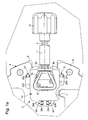
- FIG 1a is a plan view showing an overview of a crown rod Multifunction.
- multifunctional stem-crown is meant here an organ of control comprising a rod (designated by reference numeral 1 in the figures) that can be manipulated by the user through a crown (designated by reference numeral 10 in Figure 1a) integral with the rod 1 and whose direction of rotation and / or axial positions are translated into electrical signals through a plurality of electrical contacts actuated by the rod 1.
- These electrical contacts are arranged and arranged in the form of a compact module generally designated by the reference numeral 2 placed at the end of the rod 1 located opposite the crown 10.
- the rod 1 further comprises an annular groove 3 intended to accommodate a seal toric (not shown) provided for sealing between the rod 1 and the box (no represented) through which the rod 1 penetrates.
- the rod 1 is likely to occupy four positions distinct axial positions, namely a neutral position, two stable positions called “drawn” and an unstable position called “push”, and can also undergo rotations in clockwise and counter-clockwise.
- a neutral position two stable positions called “drawn”
- a pusher position two stable positions
- pusher an unstable position
- Figures 1a and 1b the rod 1 is illustrated in its extreme position pulled.
- the four axial positions and the direction of rotation of the rod 1 are translated into electrical signals through two sets of independent electrical contacts.
- the first set of electrical contacts comprises in particular two contact blades 21, 22 to translate the direction of rotation of the rod 1, each contact blade electrical 21, 22 delivering an electrical signal composed of an alternation of levels binary logic ("enabled” or “disabled” states) to distinguish between the two directions of rotation of the rod 1.
- the second set of electrical contacts comprises in particular two electric contact blades 23, 24 to translate the four positions axial of the rod 1, each electric contact blade 23, 24 delivering a signal binary logic type electrical which is a function of the axial position of the rod.
- a cover 7 made of an electrically insulating material (one piece advantageously made by molding a plastic) and which is made integral with a support plate generally designated by reference numeral 4.
- the face 7a upper cover 7 comprises a recess 70 of particular shape forming a housing for a spring element 9 open.
- This spring element 9 has a shape particular bend, known from the prior art, adapted to maintain the rod 1 in its three stable axial positions.
- This spring 9 is conventionally arranged to cooperate with three adjacent annular grooves formed on the body of the rod 1 and separated by beads. These annular grooves and beads are not referenced but appear clearly in Figure 1b.
- the spring 9 thus comprises two free ends 9a, 9b (oriented substantially perpendicular to the plane illustrations of Figures 1a and 1b) which extend inside the module 2, from and other of the rod 1. During an axial displacement of the rod 1, the free ends 9a and 9b spring 9 spread by sliding on the beads before closing on one of the annular grooves of the stem 1.
- the aforementioned support plate 4 here consists of two parts superimposed.
- a first lower part (or base plate) 5 is made in one electrically conductive material and is intended to be carried to a potential determined electrical power, for example the electrical potential forming the mass of a electronic module with which the control member must cooperate.
- a second upper part 6 is made of an electrically insulating material and is interposed between the base plate 5 and the various electrical contact blades 21 to 24 above.
- the support plate 4 can be considered as a support piece electrically insulated from the electrical contact blades 21 to 24. This support piece 4 can obviously take various forms.
- Figure 1b allows to better highlight the shape and configuration particular electric contact blades 21 to 24.
- the cover 7 and the spring 9 have not been shown to discover the four contact blades 21 to 24.
- the free ends 9a, 9b of the spring are shown in section to illustrate their arrangement with respect to the annular grooves of the rod 1.
- each of the electrical contact blades 21 to 24 is interposed between the support plate 4, on the one hand, and the cover 7, on the other hand go.
- each of the electrical contact blades has a portion forming base (denoted by the numerical reference of the concerned blade followed by the index a) sandwiched between the support plate 4 and the cover 7.
- Each of the electric contact blades 21 to 24 further comprises a first flexible extension (designated by the numerical reference of the blade concerned followed by the index b) connected to the base of the blade and which is likely to move freely inside the hood 7 under the action of the rod 1.
- This first flexible extension of each electric contact blade forms, strictly speaking, the moving part of each of the four electrical contacts.
- each of the blades of electrical contact 21 to 24 furthermore comprises an additional extension (designated by the numerical reference of the concerned slide followed by the index c) which is accessible from the outside of the hood 7.
- Each of these additional extensions 21c to 24c effectively forms the output terminal of each of the four electrical contacts, that is to say a terminal on which an electrical signal is delivered representative of the state (closed / open) of the corresponding electrical contact.
- These additional extensions 21c to 24c may advantageously have a shape terminal "U" (apparent in particular in Figures 2 and 3b) in the optics of being inserted into corresponding metallised holes in a wafer of printed circuit board (not shown) to which the control device is to be connected electrically.
- the electric contact blades 21 to 24 are still present in this example of the terminations 21d, 22d, 23d, 24d, respectively, leading to 7.
- These terminations 21d to 24d have no real utility from the point from the point of view of the electrical operation of the four contacts. As will be seen below, these terminations are the result of the implementation of the method of manufacture and assembly of electrical contacts according to the invention.
- the flexible extensions 21b to 24b electrical contact blades 21 to 24 are each arranged to be brought into contact with the base plate 5 under the action of the rod 1 in order to establish an electrical connection with this base plate.
- the base plate is brought to a potential determined electric, for example an electrical potential forming mass.
- the electric potential of this base plate 5 is then brought to the blade of corresponding contact and this state can be detected on the output terminal 21 d, 22d, 23d, 24d of the corresponding electrical contact.
- the end at least of the rod 1 which cooperates with the four electrical contact blades 21 to 24 is isolated electrically, here by an insulating sheath 30, the body of the rod 1 thus not being direct electrical contact blades 21 to 24.
- This insulating sheath 30 has a first portion 31 with a non-constant radius forming a cam (for example a part of rectangular section or elliptical section) for actuation of the first set of blades of electrical contact 21, 22 and a second portion 32 essentially comprising two cylindrical portions 32a, 32b of different diameters for actuating the second set of electric contact blades 23, 24.
- the first 21 and second 22 electrical contact blades of the first game are placed on either side of the rod 1, the flexible extensions 21b, 22b of these contact blades 21, 22 being oriented substantially perpendicular to the axis of the rod 1 and axially offset relative to the rod 1 so as to be able to translate the rotations of the rod 1 in the form of electrical signals.
- the extensions 21b, 22b are therefore oriented in opposite directions.
- the extensions 21b, 22b are by elsewhere bent at a point designated by the reference numeral 210, resp. 220, (cf. in particular Figures 2 and 3b) so as to be directed out of the plane where the blades are supported, in the direction of the axis of the rod 1 (the rod 1 resting at a certain distance above the electric contact blades).
- the plate support 4 is devoid of insulation, an opening 61 being provided at this point in the insulating layer 6 to expose a portion of the base plate 5.
- Note still two through holes 41, 42 are formed in the support plate 4 (through the base plate 5 and the insulating layer 6) where are formed the ends 21c, 21d and 22c, 22d of the blades 21, 22.
- the cam portion 31 of the sheath 30 actuates successively the two flexible extensions 21b, 22b of the contact blades 21, 22, causing a slight downward movement of the points 210, 220 where the flexible extensions 21 b, 22b are bent.
- These points 210, 220 are then brought into contact with the plate of base 5 through the opening 61 formed in the insulating layer 6.
- two bosses 51, 52 are arranged opposite points 210, 220 where the extensions 21b, 22b are bent (these bosses 51, 52 are indicated in lines interrupted in Figure 1 (b).
- the first 23 and second 24 electrical contact blades of the second set are placed on either side of rod 1, this time in the vicinity of the end of the rod 1 and the portion 32 of the sheath 30.
- the flexible extensions 23b, 24b of these blades 23, 24 are oriented substantially parallel to the axis of the rod 1 and again axially offset by relative to this rod 1 so as to translate the axial positions of the rod 1 in the form of electrical signals.
- Part of each flexible extension 23b, 24b is arranged to cooperate with the end 32 of the sheath 30 placed on the rod, then that another neighboring part of each flexible extension 23b, 24b is arranged to cooperate with a contact pad 53, resp.
- the flexible extensions 23b, 24b are configured and prestressed to come into contact laterally with the contact pads 53, 54 as shown in Figure 1b. This contact is maintained as long as rod 1 is not brought into a position where its end exerts an action to spread the blade corresponding.
- the two blades 23, 24 are in contact with the contact pads 53, 54.
- the stable axial position intermediate (intermediate pulled position)
- the blade 23 is spaced from the contact pad 53.
- the last stable axial position neutral position
- the blades 23, 24 are spaced contact pads 53, 54.
- the blade 23 enters temporarily in contact with the stud 53 to be discarded again after return to the neutral position, this return being ensured by the restoring force of the spring 9.
- the proposed process proceeds in the manner next.
- This process begins with the stamping and preforming of a plate of an electrically conductive material to form a base plate intermediate comprising a support structure and a plurality of electrical contact still mechanically linked to the support structure by a plurality of attachment points (see Figure 2), each electrical contact blade comprising a base and a flexible extension connected to the base to form the part mobile of an electrical contact operable by the control member.
- a positioning step see FIGS. 3a and 3b
- a fixing step see FIGS.
- the first stage of stamping and preforming is preferably carried out to produce a band comprising a plurality of identical sets of electric contact blades.
- FIG. 2 shows indeed a band 200 in electrically conductive material (for example a metal of the steel type or copper) comprising several identical sets of blades 21 to 24 for producing the electrical contacts of the aforementioned multifunctional stem-crown (several games similar are thus made on the strip 200, only two being illustrated in FIG. Figure 2).
- This band 200 is obtained according to conventional stamping methods.
- Several orifices 250 are provided on the strip 200 to allow its handling and / or its positioning.
- each of the electric contact blades 21 to 24 is mechanically linked to a support structure 25 to form the band 200, the extensions 21d to 24d aforementioned forming points of attachment between the blades 21 to 24 and the structure of support 25.
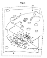
- FIG. 3a shows a perspective view of the cover 7 already mentioned, this FIG. 3a showing the rear face 7b of the cover 7.
- the four pins 75 are intended for allow the attachment of the cover 7 to the support plate 4 through holes of assembly 45 as will be seen below, while the pins 76, 77 are intended for ensure proper positioning of the cover 7 on the support plate 4.
- the cover 7 advantageously still has a set of impressions 71 to 74 corresponding to the general shape of the bases 21a to 24a of the four contact blades 21 to 24. These fingerprints promote a good hold of the various blades to mounted state.
- openings (not referenced) are also arranged to allow the passage of flexible extensions 21b to 24b blades electrical contact 21 to 24 inside the cover 7. It should be noted that the impressions could be carried out in one or other of the support pieces.
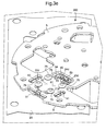
- FIG. 3b shows a next step of the method where the strip 25 comprising the blades 21 to 24 is positioned on the cover 7. It can thus see the bases 21 b to 24b blades embedded in the footprints 71 to 74 corresponding.
- the insulating layer 6 and the base plate 5 are then positioned on the strip to form the plate support 4 (FIGS. 3c and 3d).
- the tenons 75, 76, 77 of the cover 7 are housed in the mounting orifices 45, 46, 47 corresponding and that the openings 41, 42, 43 formed in the wafer support 4 provide access to the attachment points 21d to 24d of the contact blades Electric 21 to 24.
- the ends 75 of the tenons are then plastically deformed to make integral the cover 7 and the support plate 4 and maintain the various contact blades 21 to 24.
- the cover 7 could be made integral with the support plate 4 by other means (e.g. welding, gluing, clipping, screwing, etc.).
- the electrical contact blades 21 to 24 can then be detached from the support structure 25 to be rendered independent and electrically isolated from each other.
- this is advantageously achieved by using a tool (not shown) to break the various fastening points 21d to 24d of the blades through the orifices 41, 42 and 43 provided to facilitate this operation.
- the section of the contact blades can be reduced locally to favor the cutting of the blade along a determined line.
- the various electrical contacts of the control member are thus made. he all that remains is to mount the control unit strictly speaking (in the occurrence, the rod 1 provided with its crown 10 as well as the spring 9 of axial positioning of the rod 1) and to make the electrical connections between the output terminals of the electrical contacts and the appropriate electronic module.
- the rod 1 and the ring 10 are typically mounted at an ultimate stage of manufacture, in this case after assembly of the movement of the timepiece and insertion in its box.
Landscapes
- Physics & Mathematics (AREA)
- General Physics & Mathematics (AREA)
- Engineering & Computer Science (AREA)
- Manufacturing & Machinery (AREA)
- Electric Clocks (AREA)
- Manufacturing Of Electrical Connectors (AREA)
- Manufacture Of Switches (AREA)
Abstract
Description
- la figure 1a est une vue en plan d'ensemble d'une tige-couronne multifonction comprenant un jeu de quatre contacts électriques fabriqués et montés selon un mode de mise en oeuvre de l'invention ;
- la figure 1 b est une vue en plan agrandie de la figure 1a où les éléments masquant les contacts électriques ont été supprimés pour faire apparaítre les lames de contact électrique actionnées par la tige-couronne ;
- la figure 2 est une vue en perspective des lames de contact électrique de la tige-couronne multifonction de la figure 1, illustrées dans une configuration avant montage où elles sont encore solidaires d'une structure de support conformée avantageusement en bande, cette bande comportant plusieurs jeux de lames de contact électrique identiques ;
- les figures 3a à 3f illustrent chronologiquement une succession d'étapes mises en oeuvre en vue de la fabrication et du montage des contacts électriques pour la réalisation de la tige-couronne multifonction de la figure 1 a.
Claims (10)
- Procédé de fabrication et de montage de contacts électriques pour organes de commande de faibles dimensions, notamment pour organes de commande utilisés en horlogerie, caractérisé en ce qu'il comporte les étapes suivantes :a) étampage et préformage d'une plaque d'un matériau électriquement conducteur pour former une plaque de base intermédiaire (200) comprenant une structure de support (25) et une pluralité de lames de contact électrique (21 à 24) encore liées mécaniquement à ladite structure de support (25) par une pluralité de points d'attache (21d à 24d), chaque lame de contact électrique comprenant une base (21 a à 24a) et une extension flexible (21 b à 24b) reliée à ladite base pour former la partie mobile d'un contact électrique actionnable par un organe de commande (1, 10) ;b) positionnement de la plaque de base intermédiaire (200) sur une première pièce de support (7) isolée électriquement desdites lames de contact électrique (21 à 24);c) fixation sur ladite première pièce de support (7) d'une seconde pièce de support (4) isolée électriquement desdites lames de contact électrique (21 à 24) de sorte que chacune desdites lames de contact électrique (21 à 24) est maintenue entre lesdites première (7) et seconde (4) pièces de support par sa base (21a à 24a) ; etd) rupture de ladite pluralité de points d'attache (21d à 24d) reliant la pluralité de lames de contact électrique (21 à 24) à ladite structure de support (25) de sorte que toutes les lames de contact électrique (21 à 24) sont rendues indépendantes et isolées électriquement les unes des autres.
- Procédé selon la revendication 1, caractérisé en que ladite première ou seconde pièce de support (7, 4) comporte des orifices (41, 42, 43) ménagés pour faciliter la rupture de ladite pluralité de points d'attache (21d à 24d).
- Procédé selon la revendication 1 ou 2, caractérisé en ce que ladite étape de fixation de la seconde pièce de support (4) sur la première pièce de support (7) inclut notamment le soudage, le collage, le clipsage, le vissage ou le rivetage desdites première et seconde pièces de support.
- Procédé selon l'une quelconque des revendications précédentes, caractérisé en ce que ladite seconde pièce de support (4) comporte une base (5) réalisée en un matériau électriquement conducteur recouverte d'un matériau isolant (6), ladite base (5) étant destinée à être amenée à un potentiel électrique déterminé pour jouer le rôle d'une zone de contact commune à chacune desdites lames de contact électrique (21 à 24) et avec laquelle chacune des extensions flexibles (21 b à 24b) desdites lames de contact électrique peut être amenée en contact pour établir une liaison électrique, chacune desdites lames de contact électrique (21 à 24) comportant en outre une extension additionnelle (21d à 24d) formant un terminal de sortie pour chaque contact électrique.
- Procédé selon l'une quelconque des revendications précédentes, caractérisé en ce que ladite première ou seconde pièce de support (7, 4) comporte une pluralité d'empreintes (71 à 74) dans lesquelles viennent se noyer lesdites bases (21a à 24a) des lames de contact électrique (21 à 24) lors de l'étape de fixation.
- Procédé selon l'une quelconque des revendications précédentes, caractérisé en ce que la section desdites lames de contact électrique (21 à 24) est localement réduite au niveau desdits points d'attaches (21 d à 24d) pour faciliter le sectionnement des lames de contact électrique (21 à 24) lors de l'étape de rupture.
- Procédé selon l'une quelconque des revendications précédentes, caractérisé en ce que ladite étape d'étampage et de préformage inclut la préparation d'une bande (200) comprenant une pluralité de jeux identiques de lames de contact électrique (21 à 24).
- Procédé selon l'une quelconque des revendications précédentes, pour la réalisation d'une tige-couronne multifonction (1, 10) de pièce d'horlogerie, caractérisé en ce que ladite étape d'étampage et de préformage inclut la préparation d'un premier jeu de lames de contact électrique (21, 22) pour la détection de rotations de ladite tige-couronne et d'un second jeu de lames de contact électrique (23, 24) pour la détection de positions axiales de ladite tige-couronne.
- Procédé selon la revendication 8, caractérisé en ce que ladite tige-couronne (1, 10) comporte une extrémité (30) électriquement isolée pour actionner lesdites lames de contact électrique (21 à 24), ladite extrémité (30) comportant une première partie (31) à rayon non constant formant came pour l'actionnement dudit premier jeu de lames de contact électrique (21, 22) et une seconde partie (32) comprenant plusieurs portions cylindriques (32a, 32b) de diamètres différents pour l'actionnement dudit second jeu de lames de contact électrique (23, 24).
- Procédé selon la revendication 9, caractérisé en ce que ledit premier jeu de lames de contact électrique comporte des première (21) et seconde (22) lames de contact électrique placées de part et d'autre de la tige-couronne (1, 10), les extensions flexibles (21 b, 22b) desdites première et seconde lames de contact électrique (21, 22) étant orientées sensiblement perpendiculairement à l'axe de la tige-couronne et décalées axialement par rapport à la tige-couronne de manière à pouvoir traduire les rotations de ladite tige-couronne sous forme de signaux électriques,
et en ce que ledit second jeu de lames de contact électrique comporte des troisième (23) et quatrième (24) lames de contact électrique placées de part et d'autre de la tige-couronne (1, 10), les extensions flexibles (23b, 24b) desdites troisième et quatrième lames de contact électrique (23, 24) étant orientées sensiblement parallèlement à l'axe de la tige-couronne et décalées axialement par rapport à la tige-couronne de manière à pouvoir traduire les positions axiales de ladite tige-couronne sous forme de signaux électriques.
Priority Applications (9)
| Application Number | Priority Date | Filing Date | Title |
|---|---|---|---|
| DE60332728T DE60332728D1 (de) | 2003-09-09 | 2003-09-09 | Verfahren zur Produktion und zur Montage von elektrischen Kontakten für kleine Schalter, die insbesondere in Uhrmacherei benutzt werden |
| EP03020320A EP1515203B1 (fr) | 2003-09-09 | 2003-09-09 | Procédé de fabrication et de montage de contacts électriques pour organes de commande de faibles dimensions, notamment pour l'horlogerie |
| US10/923,791 US7302758B2 (en) | 2003-09-09 | 2004-08-24 | Manufacturing and mounting method of electrical contacts for control members of small dimensions, in particular for the horological field |
| TW093125592A TWI372951B (en) | 2003-09-09 | 2004-08-26 | Manufacturing and mounting method of electrical contacts for control members of small dimensions, in particular for the horological field |
| SG200405612A SG110191A1 (en) | 2003-09-09 | 2004-08-30 | Manufacture and mounting method of electrical contacts for control members of small dimensions, in particular for the horological field |
| KR1020040069760A KR100998403B1 (ko) | 2003-09-09 | 2004-09-02 | 시계분야의 작은 크기의 제어부재를 위한 전기 접점의제조 및 부착 방법 |
| CN2004100791108A CN1595573B (zh) | 2003-09-09 | 2004-09-08 | 钟表领域的小尺寸控制件的电接触件的制造和安装方法 |
| JP2004262042A JP4575091B2 (ja) | 2003-09-09 | 2004-09-09 | 小さい寸法の制御部材、特に時計分野のための制御部材用電気接点の製造と取り付け方法 |
| HK05107427.3A HK1075129B (en) | 2003-09-09 | 2005-08-24 | Manufacturing and mounting method of electrical contacts for control members of small dimensions for the horological field |
Applications Claiming Priority (1)
| Application Number | Priority Date | Filing Date | Title |
|---|---|---|---|
| EP03020320A EP1515203B1 (fr) | 2003-09-09 | 2003-09-09 | Procédé de fabrication et de montage de contacts électriques pour organes de commande de faibles dimensions, notamment pour l'horlogerie |
Publications (2)
| Publication Number | Publication Date |
|---|---|
| EP1515203A1 true EP1515203A1 (fr) | 2005-03-16 |
| EP1515203B1 EP1515203B1 (fr) | 2010-05-26 |
Family
ID=34130165
Family Applications (1)
| Application Number | Title | Priority Date | Filing Date |
|---|---|---|---|
| EP03020320A Expired - Lifetime EP1515203B1 (fr) | 2003-09-09 | 2003-09-09 | Procédé de fabrication et de montage de contacts électriques pour organes de commande de faibles dimensions, notamment pour l'horlogerie |
Country Status (8)
| Country | Link |
|---|---|
| US (1) | US7302758B2 (fr) |
| EP (1) | EP1515203B1 (fr) |
| JP (1) | JP4575091B2 (fr) |
| KR (1) | KR100998403B1 (fr) |
| CN (1) | CN1595573B (fr) |
| DE (1) | DE60332728D1 (fr) |
| SG (1) | SG110191A1 (fr) |
| TW (1) | TWI372951B (fr) |
Cited By (1)
| Publication number | Priority date | Publication date | Assignee | Title |
|---|---|---|---|---|
| EP3506025A1 (fr) * | 2017-12-27 | 2019-07-03 | ETA SA Manufacture Horlogère Suisse | Dispositif de commande d'au moins une fonction électronique d'un objet portable |
Families Citing this family (7)
| Publication number | Priority date | Publication date | Assignee | Title |
|---|---|---|---|---|
| JP2007071748A (ja) * | 2005-09-08 | 2007-03-22 | Ricoh Elemex Corp | 携帯機器の外部操作ユニット、および携帯機器 |
| EP2072008A3 (fr) * | 2007-12-19 | 2013-04-17 | Beppo Hilfiker | Dispositif destiné à la commande d'un appareil électronique multifonction |
| US8710958B2 (en) * | 2008-07-10 | 2014-04-29 | Abbott Laboratories | Containers having radio frequency identification tags and method of applying radio frequency identification tags to containers |
| FI124328B (fi) * | 2008-12-31 | 2014-06-30 | Suunto Oy | Kaksitoiminen säätöelin rannetietokoneelle tai vastaavalle ja menetelmä rannetietokoneen tai vastaavan päätelaitteen säätämiseksi |
| EP2605087B1 (fr) * | 2011-12-13 | 2017-07-26 | ETA SA Manufacture Horlogère Suisse | Ensemble modulaire d'horlogerie à modules fonctionnels |
| EP3418813A1 (fr) * | 2017-06-23 | 2018-12-26 | ETA SA Manufacture Horlogère Suisse | Dispositif de commande a couronne-poussoir pour un objet portable de petites dimensions |
| CN110706956B (zh) * | 2019-11-04 | 2021-09-14 | 深圳市港源微键技术有限公司 | 一种轻触开关底座及其制作方法 |
Citations (6)
| Publication number | Priority date | Publication date | Assignee | Title |
|---|---|---|---|---|
| DE3611224A1 (de) * | 1986-04-04 | 1987-10-08 | Siemens Ag | Herstellungsverfahren eines kombinationsteils aus kunststoff mit einem einlegeteil |
| US4944691A (en) * | 1988-08-15 | 1990-07-31 | Cooper Industries, Inc. | Holder for a removable circuit element |
| US6146010A (en) * | 1999-03-08 | 2000-11-14 | Timex Corporation | Combined crown and pusher electro mechanism |
| US6203190B1 (en) * | 1999-06-07 | 2001-03-20 | Timex Corporation | Crown switching mechanism |
| US20020061686A1 (en) * | 2000-11-21 | 2002-05-23 | Ma Xue Dong | Method for forming an electrical connector and an electrical connector obtained thereby |
| US6422740B1 (en) * | 1999-09-01 | 2002-07-23 | Montres Rolex S. A. | Wristwatch |
Family Cites Families (10)
| Publication number | Priority date | Publication date | Assignee | Title |
|---|---|---|---|---|
| US3391456A (en) * | 1965-04-30 | 1968-07-09 | Sylvania Electric Prod | Multiple segment array making |
| JPS5631429U (fr) * | 1979-08-20 | 1981-03-27 | ||
| US4500579A (en) * | 1982-09-29 | 1985-02-19 | Norden Alexander | Sticks of parts and their use |
| JP2625481B2 (ja) * | 1988-03-14 | 1997-07-02 | アルプス電気株式会社 | スイツチ用ウエハの製造方法 |
| US5010214A (en) * | 1988-08-11 | 1991-04-23 | Atsuo Yamazaki | Rotary switch |
| US5305291A (en) * | 1993-09-22 | 1994-04-19 | Timex Corporation | Alarm setting and actuating mechanism for analog timepiece |
| US6595788B2 (en) * | 1999-10-14 | 2003-07-22 | Berg Technology, Inc. | Electrical connector with continuous strip contacts |
| CN1164015C (zh) * | 2000-12-07 | 2004-08-25 | 富士康(昆山)电脑接插件有限公司 | 电连接器及其端子芯座之制造方法 |
| JP4506052B2 (ja) * | 2001-08-09 | 2010-07-21 | 住友電装株式会社 | コネクタ |
| EP1480240A1 (fr) | 2003-05-22 | 2004-11-24 | ETA SA Manufacture Horlogère Suisse | Dipositif de commande rotatif pour appareil électronique |
-
2003
- 2003-09-09 DE DE60332728T patent/DE60332728D1/de not_active Expired - Lifetime
- 2003-09-09 EP EP03020320A patent/EP1515203B1/fr not_active Expired - Lifetime
-
2004
- 2004-08-24 US US10/923,791 patent/US7302758B2/en not_active Expired - Lifetime
- 2004-08-26 TW TW093125592A patent/TWI372951B/zh not_active IP Right Cessation
- 2004-08-30 SG SG200405612A patent/SG110191A1/en unknown
- 2004-09-02 KR KR1020040069760A patent/KR100998403B1/ko not_active Expired - Fee Related
- 2004-09-08 CN CN2004100791108A patent/CN1595573B/zh not_active Expired - Lifetime
- 2004-09-09 JP JP2004262042A patent/JP4575091B2/ja not_active Expired - Lifetime
Patent Citations (6)
| Publication number | Priority date | Publication date | Assignee | Title |
|---|---|---|---|---|
| DE3611224A1 (de) * | 1986-04-04 | 1987-10-08 | Siemens Ag | Herstellungsverfahren eines kombinationsteils aus kunststoff mit einem einlegeteil |
| US4944691A (en) * | 1988-08-15 | 1990-07-31 | Cooper Industries, Inc. | Holder for a removable circuit element |
| US6146010A (en) * | 1999-03-08 | 2000-11-14 | Timex Corporation | Combined crown and pusher electro mechanism |
| US6203190B1 (en) * | 1999-06-07 | 2001-03-20 | Timex Corporation | Crown switching mechanism |
| US6422740B1 (en) * | 1999-09-01 | 2002-07-23 | Montres Rolex S. A. | Wristwatch |
| US20020061686A1 (en) * | 2000-11-21 | 2002-05-23 | Ma Xue Dong | Method for forming an electrical connector and an electrical connector obtained thereby |
Cited By (5)
| Publication number | Priority date | Publication date | Assignee | Title |
|---|---|---|---|---|
| EP3506025A1 (fr) * | 2017-12-27 | 2019-07-03 | ETA SA Manufacture Horlogère Suisse | Dispositif de commande d'au moins une fonction électronique d'un objet portable |
| WO2019129492A1 (fr) * | 2017-12-27 | 2019-07-04 | Eta Sa Manufacture Horlogère Suisse | Dispositif de commande d'au moins une fonction électronique d'un objet portable |
| CN111556984A (zh) * | 2017-12-27 | 2020-08-18 | Eta瑞士钟表制造股份有限公司 | 便携式物体的至少一种电子功能的控制装置 |
| CN111556984B (zh) * | 2017-12-27 | 2022-06-21 | Eta瑞士钟表制造股份有限公司 | 便携式物体的至少一种电子功能的控制装置 |
| US11480928B2 (en) | 2017-12-27 | 2022-10-25 | Eta Sa Manufacture Horlogere Suisse | Device for controlling at least one electronic function of a portable object |
Also Published As
| Publication number | Publication date |
|---|---|
| CN1595573A (zh) | 2005-03-16 |
| HK1075129A1 (zh) | 2005-12-02 |
| TWI372951B (en) | 2012-09-21 |
| EP1515203B1 (fr) | 2010-05-26 |
| KR20050026336A (ko) | 2005-03-15 |
| JP4575091B2 (ja) | 2010-11-04 |
| JP2005084052A (ja) | 2005-03-31 |
| US20050050718A1 (en) | 2005-03-10 |
| DE60332728D1 (de) | 2010-07-08 |
| TW200512551A (en) | 2005-04-01 |
| US7302758B2 (en) | 2007-12-04 |
| KR100998403B1 (ko) | 2010-12-03 |
| SG110191A1 (en) | 2005-04-28 |
| CN1595573B (zh) | 2010-06-09 |
Similar Documents
| Publication | Publication Date | Title |
|---|---|---|
| EP1604085B1 (fr) | Boitier de cle | |
| EP3399532B1 (fr) | Dispositif d'arrêt d'urgence | |
| FR2754934A1 (fr) | Corps de contact mobile de commutateur de panneau et commutateur de panneau faisant appel a ce corps de contact mobile | |
| EP3457222B1 (fr) | Boite de montre comportant des cornes mobiles | |
| EP1515203B1 (fr) | Procédé de fabrication et de montage de contacts électriques pour organes de commande de faibles dimensions, notamment pour l'horlogerie | |
| EP0186804B1 (fr) | Dispositif électronique perfectionné destiné à être porté au poignet | |
| EP1519457B1 (fr) | Adaptateur pour instrument électronique portable et système de transmission entre ces deux éléments | |
| EP0024364A1 (fr) | Dispositif de maintien d'une pile dans une montre-bracelet électronique | |
| FR2856191A1 (fr) | Dispositif de commande a tambour et a voies de commutation multiples, et appareil electronique equipe de tels dispositifs | |
| FR2969367A1 (fr) | Appareil de coupure electrique | |
| FR2460536A1 (fr) | Interrupteur multiple selectif, notamment pour vehicules automobiles | |
| EP1139060B1 (fr) | Initiateur pyrotechnique pouvant être équipé d'un composant électrique ou électronique et/ou d'un connecteur | |
| FR2775798A1 (fr) | Boite de montre munie de moyens de commande | |
| EP1435633B1 (fr) | Dispositif de commande à positions axiales multiples pour appareil électronique | |
| EP0954051A1 (fr) | Antenne à fente, notamment pour pièce d'horlogerie | |
| FR2784148A1 (fr) | Dispositif d'accouplement entre un bouton de commande et un mecanisme | |
| FR2846468A1 (fr) | Organe de commande a bouton de manipulation rotatif autour de plusieurs axes | |
| EP1558973B1 (fr) | Dispositif de commande pour poussoir, notamment de piece d'horlogerie | |
| FR2993700A1 (fr) | "commutateur electrique a effet tactile a bruit reduit et procede d'attenuation du bruit d'un commutateur a effet tactile" | |
| EP1109084B1 (fr) | Moyens pour recharger l'accumulateur d'une montre | |
| EP0489654B1 (fr) | Ensemble de commutation pour véhicules automobiles | |
| CH713298A2 (fr) | Objet portable comportant un dispositif de connexion en champ proche. | |
| EP3651173A1 (fr) | Ensemble de commutation à solution d'accrochage sécurisé pour dispositif d'arrêt d'urgence | |
| WO2008062015A1 (fr) | Module de commutation electrique avec composants electroniques de type cms | |
| EP0720250B1 (fr) | Antenne pour véhicule automobile et ensemble adaptateur actif d'impédance pour une telle antenne |
Legal Events
| Date | Code | Title | Description |
|---|---|---|---|
| PUAI | Public reference made under article 153(3) epc to a published international application that has entered the european phase |
Free format text: ORIGINAL CODE: 0009012 |
|
| AK | Designated contracting states |
Kind code of ref document: A1 Designated state(s): AT BE BG CH CY CZ DE DK EE ES FI FR GB GR HU IE IT LI LU MC NL PT RO SE SI SK TR |
|
| AX | Request for extension of the european patent |
Extension state: AL LT LV MK |
|
| RIN1 | Information on inventor provided before grant (corrected) |
Inventor name: KAELIN, LAURENT Inventor name: WYSSBROD, BAPTIST Inventor name: HUNZIKER, YANNICK |
|
| 17P | Request for examination filed |
Effective date: 20050916 |
|
| AKX | Designation fees paid |
Designated state(s): CH DE FR LI |
|
| RTI1 | Title (correction) |
Free format text: MANUFACTURING AND ASSEMBLY METHOD ELECTRICAL CONTACTS FOR SMALL SIZED SWITCHES, IN PARTICULAR USED IN WATCH MAKING |
|
| GRAP | Despatch of communication of intention to grant a patent |
Free format text: ORIGINAL CODE: EPIDOSNIGR1 |
|
| GRAS | Grant fee paid |
Free format text: ORIGINAL CODE: EPIDOSNIGR3 |
|
| GRAA | (expected) grant |
Free format text: ORIGINAL CODE: 0009210 |
|
| AK | Designated contracting states |
Kind code of ref document: B1 Designated state(s): CH DE FR LI |
|
| REG | Reference to a national code |
Ref country code: CH Ref legal event code: EP Ref country code: CH Ref legal event code: NV Representative=s name: ICB INGENIEURS CONSEILS EN BREVETS SA |
|
| REF | Corresponds to: |
Ref document number: 60332728 Country of ref document: DE Date of ref document: 20100708 Kind code of ref document: P |
|
| PLBE | No opposition filed within time limit |
Free format text: ORIGINAL CODE: 0009261 |
|
| STAA | Information on the status of an ep patent application or granted ep patent |
Free format text: STATUS: NO OPPOSITION FILED WITHIN TIME LIMIT |
|
| 26N | No opposition filed |
Effective date: 20110301 |
|
| REG | Reference to a national code |
Ref country code: DE Ref legal event code: R097 Ref document number: 60332728 Country of ref document: DE Effective date: 20110228 |
|
| REG | Reference to a national code |
Ref country code: FR Ref legal event code: PLFP Year of fee payment: 13 |
|
| REG | Reference to a national code |
Ref country code: FR Ref legal event code: PLFP Year of fee payment: 14 |
|
| REG | Reference to a national code |
Ref country code: FR Ref legal event code: PLFP Year of fee payment: 15 |
|
| REG | Reference to a national code |
Ref country code: FR Ref legal event code: PLFP Year of fee payment: 16 |
|
| PGFP | Annual fee paid to national office [announced via postgrant information from national office to epo] |
Ref country code: DE Payment date: 20220616 Year of fee payment: 20 |
|
| PGFP | Annual fee paid to national office [announced via postgrant information from national office to epo] |
Ref country code: FR Payment date: 20220818 Year of fee payment: 20 |
|
| PGFP | Annual fee paid to national office [announced via postgrant information from national office to epo] |
Ref country code: CH Payment date: 20221001 Year of fee payment: 20 |
|
| P01 | Opt-out of the competence of the unified patent court (upc) registered |
Effective date: 20230701 |
|
| REG | Reference to a national code |
Ref country code: DE Ref legal event code: R071 Ref document number: 60332728 Country of ref document: DE |
|
| REG | Reference to a national code |
Ref country code: CH Ref legal event code: PL |