EP1515094A2 - Heizplatte zum elektrischen Heizen von Gebäuderäumen - Google Patents
Heizplatte zum elektrischen Heizen von Gebäuderäumen Download PDFInfo
- Publication number
- EP1515094A2 EP1515094A2 EP04019287A EP04019287A EP1515094A2 EP 1515094 A2 EP1515094 A2 EP 1515094A2 EP 04019287 A EP04019287 A EP 04019287A EP 04019287 A EP04019287 A EP 04019287A EP 1515094 A2 EP1515094 A2 EP 1515094A2
- Authority
- EP
- European Patent Office
- Prior art keywords
- heating
- base plate
- heating plate
- plate
- plates
- Prior art date
- Legal status (The legal status is an assumption and is not a legal conclusion. Google has not performed a legal analysis and makes no representation as to the accuracy of the status listed.)
- Withdrawn
Links
Images

Classifications
-
- H—ELECTRICITY
- H05—ELECTRIC TECHNIQUES NOT OTHERWISE PROVIDED FOR
- H05B—ELECTRIC HEATING; ELECTRIC LIGHT SOURCES NOT OTHERWISE PROVIDED FOR; CIRCUIT ARRANGEMENTS FOR ELECTRIC LIGHT SOURCES, IN GENERAL
- H05B3/00—Ohmic-resistance heating
- H05B3/20—Heating elements having extended surface area substantially in a two-dimensional [2D] plane, e.g. plate-heater
- H05B3/22—Heating elements having extended surface area substantially in a two-dimensional [2D] plane, e.g. plate-heater non-flexible
- H05B3/26—Heating elements having extended surface area substantially in a two-dimensional [2D] plane, e.g. plate-heater non-flexible heating conductor mounted on insulating base
- H05B3/265—Heating elements having extended surface area substantially in a two-dimensional [2D] plane, e.g. plate-heater non-flexible heating conductor mounted on insulating base the insulating base being an inorganic material, e.g. ceramic
-
- F—MECHANICAL ENGINEERING; LIGHTING; HEATING; WEAPONS; BLASTING
- F24—HEATING; RANGES; VENTILATING
- F24D—DOMESTIC- OR SPACE-HEATING SYSTEMS, e.g. CENTRAL HEATING SYSTEMS; DOMESTIC HOT-WATER SUPPLY SYSTEMS; ELEMENTS OR COMPONENTS THEREFOR
- F24D13/00—Electric heating systems
- F24D13/02—Electric heating systems solely using resistance heating, e.g. underfloor heating
- F24D13/022—Electric heating systems solely using resistance heating, e.g. underfloor heating resistances incorporated in construction elements
-
- H—ELECTRICITY
- H05—ELECTRIC TECHNIQUES NOT OTHERWISE PROVIDED FOR
- H05B—ELECTRIC HEATING; ELECTRIC LIGHT SOURCES NOT OTHERWISE PROVIDED FOR; CIRCUIT ARRANGEMENTS FOR ELECTRIC LIGHT SOURCES, IN GENERAL
- H05B3/00—Ohmic-resistance heating
- H05B3/20—Heating elements having extended surface area substantially in a two-dimensional [2D] plane, e.g. plate-heater
- H05B3/34—Heating elements having extended surface area substantially in a two-dimensional [2D] plane, e.g. plate-heater flexible, e.g. heating nets or webs
-
- H—ELECTRICITY
- H05—ELECTRIC TECHNIQUES NOT OTHERWISE PROVIDED FOR
- H05B—ELECTRIC HEATING; ELECTRIC LIGHT SOURCES NOT OTHERWISE PROVIDED FOR; CIRCUIT ARRANGEMENTS FOR ELECTRIC LIGHT SOURCES, IN GENERAL
- H05B2203/00—Aspects relating to Ohmic resistive heating covered by group H05B3/00
- H05B2203/011—Heaters using laterally extending conductive material as connecting means
-
- H—ELECTRICITY
- H05—ELECTRIC TECHNIQUES NOT OTHERWISE PROVIDED FOR
- H05B—ELECTRIC HEATING; ELECTRIC LIGHT SOURCES NOT OTHERWISE PROVIDED FOR; CIRCUIT ARRANGEMENTS FOR ELECTRIC LIGHT SOURCES, IN GENERAL
- H05B2203/00—Aspects relating to Ohmic resistive heating covered by group H05B3/00
- H05B2203/013—Heaters using resistive films or coatings
-
- H—ELECTRICITY
- H05—ELECTRIC TECHNIQUES NOT OTHERWISE PROVIDED FOR
- H05B—ELECTRIC HEATING; ELECTRIC LIGHT SOURCES NOT OTHERWISE PROVIDED FOR; CIRCUIT ARRANGEMENTS FOR ELECTRIC LIGHT SOURCES, IN GENERAL
- H05B2203/00—Aspects relating to Ohmic resistive heating covered by group H05B3/00
- H05B2203/034—Heater using resistive elements made of short fibbers of conductive material
-
- Y—GENERAL TAGGING OF NEW TECHNOLOGICAL DEVELOPMENTS; GENERAL TAGGING OF CROSS-SECTIONAL TECHNOLOGIES SPANNING OVER SEVERAL SECTIONS OF THE IPC; TECHNICAL SUBJECTS COVERED BY FORMER USPC CROSS-REFERENCE ART COLLECTIONS [XRACs] AND DIGESTS
- Y02—TECHNOLOGIES OR APPLICATIONS FOR MITIGATION OR ADAPTATION AGAINST CLIMATE CHANGE
- Y02B—CLIMATE CHANGE MITIGATION TECHNOLOGIES RELATED TO BUILDINGS, e.g. HOUSING, HOUSE APPLIANCES OR RELATED END-USER APPLICATIONS
- Y02B30/00—Energy efficient heating, ventilation or air conditioning [HVAC]
Definitions
- the invention relates to a heating plate for the electrical heating of building spaces, characterized, that it has a base plate made of mineral material and having internal pores; and that a connectable to the mains, electric heating mat is mounted on a flat side of the base plate.
- the heating plate according to the invention has due to the material structure of Base plate a heat-insulating effect.
- the heating plate gives off its heat large area and largely as radiant heat from, so that in the Room in which the heating plate is provided, a comfortable, even Room climate results.
- the heating plate is a very compact, visually extremely inconspicuous Heating element. By selecting the size of the installed hot plate and / or by choosing the number of installed hot plates is very simply make an installation according to the desired heating demand.
- the heating plate is extremely easy to install, preferably by Attachment to a room wall with a so-called. System adhesive and by electrical Connect.
- the base plate represents the mechanical one Supporting structure of the heating mat; this mechanical support structure is - measured in size - light and also has - as already mentioned - heat-insulating Effect.
- the base plate on The reason of their material structure has a moisture-balancing effect.
- the base plate absorbs moisture on and gives the moisture distributed over time back to the surrounding Air as soon as the air is receptive to this.
- This moisture balancing Effect is indeed because of the attached heating mat in many cases only weakened, but tangible. But there are also cases where the moisture balancing effect quite quite present is, e.g. if you think of the situation that the heating mat is much smaller than the relevant flat side of the base plate is.
- the inventive Form heating plate as a double-sided heating plate. As an an example May one imagine a room divider that is only part of the height of a room, or the railing-like boundary of a gallery.
- the heating plate according to the invention not only for attachment is usable on a room wall or for installation freely in a room, but that by means of the heating plate according to the invention also Bodenheitzung and ceiling heating can realize.
- a preferred embodiment of the invention is - possibly respective - Flat side of the base plate on which one or more heating mats are mounted are at least 75%, preferably at least 90%, with the heating mat (s) covered. It is therefore preferable to use the size of the flat side of the Base plate as far as possible for heat dissipation.
- the heating mat is preferably designed to operate on each Place their area has substantially the same heat generation.
- a particularly preferred embodiment of the heating plate has a heating mat auf, as the electrically conductive in operation, heat-generating component Having carbon fibers.
- the carbon fibers make a total of a sheet where there is nowhere small area elements without heat generation gives.
- the sheet of carbon fiber may in particular be a fabric or a fleece or scrim made of carbon fibers; Such structures are made the production of fiber-reinforced plastic components known. It must not be that the carbon fibers are the sole, electrically conductive component of the Heating mat are. There may be one or more, additional, electrically conductive Components are added, especially soot.
- the heating mat is particularly preferred to embed the heating mat as a plastic mat with Carbon fibers (optional addition of other, electrically conductive component) provided.
- a plastic mat can be in the manufacture of the heating plate easy to handle.
- the heating mat is on its side facing away from the base plate covered, more preferably covered by a filler.
- Another preferred cover would be a wallpaper.
- the cover makes the Heating mat invisible, and you can not see at all, that you have a heating element instead of a room wall in front of him.
- the Heating mat by means of the mentioned putty (or other putty) attach to the base plate. In this way you can practically in a single operation mounting the heating mat and covering the Carry out the heating mat. Working with a putty is also then very handy considering the distances between adjacent heating mats or the margins between the edges of the heating mat and the edge of the would like to fill out the heating plate.
- the heating plate is rectangular with a length of 50 to 150 cm, especially 80 to 120 cm in one direction and with a length of 40 to 120 cm, more preferably 60 to 90 cm, in the other direction. baseplates in this size range can be easily produced and handled.
- the base plate (especially preferably only on one side) with a single heating mat to equip (the most preferably almost the entire surface of the flat side of the base plate occupies). If a manufacturer has a production program of several hotplates In this case he would have different heating mats Process size. On the other hand, there are manufacturing processes, where it is more practical, at least for the heating plates larger format to work side by side with several heating mats. This can be on it In addition to running a heater mats only one format (or very much less different formats) and still processed a larger number different heating plate formats can deliver.
- the base plate of the heating plate 15 to 70 mm, particularly preferred 20 to 40 mm, thick is preferred.
- This thickness range represents an optimal compromise from the point of view of adequate mechanical strength, easy handling when mounting in the building and sensible thermal insulation effect represents.
- the base plate substantially Sand, mineral binder, optionally at least one porous aggregate, and optionally a porosifying agent in the starting composition.
- a non-cemental lime binder is preferred.
- As an aggregate especially pumice, puffed perlite, expanded clay, Blown mica, expanded glass, foamed polystyrene. Come as a porosity agent especially suitable surfactants, aluminum powder, peroxo compounds. But there are certainly manufacturing processes in which the pores in the Base plate by evaporation of the contained in the starting composition Waters are generated and those without a separate porosity agent get along. Panels conforming to the above specification of composition meet are known. Except the mentioned components can other ingredients may be included in a smaller amount.
- the base plate has a specific gravity of less than 250 kg / m 3 .
- Low specific weight means good workability in construction, low price per unit area of the base plate and good thermal insulation effect.
- the heating plate should have a reasonable mechanical strength, which limits too much lowering of the specific weight of the base plate limits.
- the heating plate according to the invention is designed so that it has a heat generation of 100 to 300 W / m 2 , particularly preferably 140 to 250 W / m 2 , in operation per unit area of its flat side.
- Such heat generation densities - depending on the prevailing air temperature in the room - to pleasant surface temperatures of the heat-emitting flat side of the hot plate during operation.
- it can be achieved that with a small number (if you are dealing with a room that has a usual size for living space) or a manageable number (if you are dealing with a much larger room) of hotplates a meaningful heating result achieved.
- Another object of the invention is a room of a building, characterized, in that it has on the inside of at least one wall at least one heating plate as disclosed in the present application.
- the space has a plurality of heating plates according to the invention, especially prefers several heating plates on at least one wall above the other and / or next to each other.
- it is sufficient heating plates only on a wall, e.g. on an exterior wall of the building.
- it is in the interest of uniform heat input in the room is more reasonable, several walls with hotplates too Mistake.
- the situation that the room only provided with a single hot plate is likely to be a rather rare situation.
- Several heating plates can, But they do not have to be positioned close to each other and / or one above the other be.
- the space at the Inside at least one wall at least one attachment plate on, the off mineral material and having inner pores, more preferably material is essentially constructed as the base plate of heating plate according to the invention.
- the attachment plate can (or the attachment plates can be installed or attached to the same wall as the hot plate (s) another wall (or walls) of the room. In the former case, the Attachment plates usually mounted in such area of the wall where no Heating plates are attached.
- the attachment plates are used for thermal insulation and the temporal moisture balance, as initially associated with the base plate of the heating plate according to the invention described.
- the inventive Heating plate (s) with the front plate (s), as described in the above Paragraph is described (are), can be optimally combined (can).
- the base plates for the heating plates according to the invention from the same production as the attachment plates.
- the heating plates slightly thicker because of the respective applied heating mat, which one with combined placement of heating plates and attachment plates on one Wall e.g. through a slightly thicker layer of system adhesive when mounting compensate for the relevant attachment plate.
- Another possibility is to make the base plates for the heating plates so much thinner, that comes in handy for each with heating mat completed heating plates the same thickness as the front panels results.
- the delivery formats the attachment plates at least partly the same as the delivery formats the heating plates.
- the attachment plates can be cut very easily, e.g. by means of a motor saw. As a result, one can fill in the gaps that are for a given wall length or ceiling height and use of the available formats the heating plates yield, easily with cut attachment plate pieces fill up.
- the hot plates according to the invention and the described attachment plates preferably by means of a so-called.
- Fix system adhesive to the room wall There are system adhesives that are more mortar-like with the adhesion-enhancing additives. But there is also system adhesives that have a high content of plastic and practical no mineral binder included.
- After attaching the plates to the Wall can be e.g. Fill the joints between the plates and then to paint the wall.
- An alternative is the sticking of a wallpaper, optionally without prior filling of the joints.
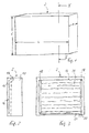
- the drawn in Fig. 1 heating plate 2 has the overall shape of a flat Cuboid with a length 4 of 1000 mm, a width 6 of 750 mm and a Thickness 8 of 30 mm.
- the heating plate 2 made a base plate 10 with a thickness of 24 mm and a heating mat 12, the in Fig. 2 pointing to the left flat side 14 of the base plate 10 at this is attached by means of a filler 16 exists.
- the mentioned flat side 14, i. the interface between the base plate 10 and the putty 16, is shown in broken line.
- the filler 16 covered the left in Fig. 2 facing surface of the heating mat 12, so that there is an im essential level end surface of the heating plate 2 is formed and the heating mat 12 is not visible.
- the heating mat 12 is in the viewing direction of Fig. 3, i. on one of its two flat sides, essentially rectangular and only slightly smaller than the flat side 14 of the base plate 10.
- the heating mat 12 has a bordering edge 18 of an electrically good conductive material, e.g. Copper foil, on.
- Each bordering edge 18 is with a insulated conductor 20 is connected, and the two current conductors 20 are connected to a Edge of the heating plate 2 led out. By means of these two conductors 20 leaves the heating plate 2 connect to a power grid.
- Carbon fiber fabric 21 extending between the two skirting boards 18 extends.
- a single heating mat 12 can also several heating mats 12 with little or greater distance next to each other be mounted on the flat side 14 of the base plate 10. You can electrically connected in parallel or in series. It is best if also in this case, only a single pair of conductors 20 from the heating plate 10 leads away.
- FIG. 4 shows a "corner cutout" of a room 22 of a building.
- the first wall 26 is entirely with on its inside clad panels attached; it is e.g. around an outside wall of the Space 22.
- the second wall 28 is not clad with panels; It is about e.g. around a wall with windows or around an inner wall of the room 22.
- first wall 26 On the first wall 26 can be seen a lowermost, first row of heating plates 2, which are positioned close together. You can see one above second row of plates 30. These are plates that materially so are formed as the base plates 10 of the heating plates 2 and in general Part of the description have been referred to as header plates. at In this embodiment, the plates 30 also have a thickness of 30 mm, so are slightly thicker than the base plates 10 of the heating plates. 2 Finally, one sees a third row of plates 30 positioned above Heating plates 2, the attachment plates 30 and not drawn plate sections to fill in the gaps, the entire first wall 26 clad from the left right and from bottom to top.
- Fig. 4 On the basis of Fig. 4 is clearly visible how to get by means of the invention retrofit the room 22 with a heater or modernize the heating technology can and at the same time in terms of thermal insulation and moisture regulation can bring to a better state, and with a comparatively small use of remodeling work, low pollution, little intervention in neighboring rooms and the like. It only need the Hot plates 2 are attached and electrically connected and the attachment plates 30 are attached. Then it is overpainted or overpainted. The space 22 has only minimally diminished and is in its appearance remained unchanged.
- the inner wall cladding from the plates 2 and Of course, 30 also includes any cracks in the first wall 26 (e.g., old ones) Half timbered houses!) Windproof.
- Vorsatzplatten 30 can be provided, in the wall areas between or next to the windows or doors.
Landscapes
- Engineering & Computer Science (AREA)
- Chemical & Material Sciences (AREA)
- Physics & Mathematics (AREA)
- Thermal Sciences (AREA)
- Combustion & Propulsion (AREA)
- Mechanical Engineering (AREA)
- General Engineering & Computer Science (AREA)
- Ceramic Engineering (AREA)
- Surface Heating Bodies (AREA)
- Central Heating Systems (AREA)
- Resistance Heating (AREA)
Abstract
dass sie eine Grundplatte (10) aufweist, die aus mineralischem Material besteht und innere Poren aufweist;
und dass eine an das Stromnetz anschließbare, elektrische Heizmatte (12) auf einer Flachseite (14) der Grundplatte (10) angebracht ist.
Description
dadurch gekennzeichnet,
dass sie eine Grundplatte aufweist, die aus mineralischem Material besteht und innere Poren aufweist;
und dass eine an das Stromnetz anschließbare, elektrische Heizmatte auf einer Flachseite der Grundplatte angebracht ist.
dadurch gekennzeichnet,
dass er an der Innenseite mindestens einer Wand mindestens eine Heizplatte, wie sie in der vorliegenden Anmeldung offenbart ist, aufweist.
Claims (19)
- Heizplatte zum elektrischen Heizen von Gebäuderäumen (22),
dadurch gekennzeichnet, dass sie eine Grundplatte (10) aufweist, die aus mineralischem Material besteht und innere Poren aufweist;
und dass eine an das Stromnetz anschließbare, elektrische Heizmatte (12) auf einer Flachseite (14) der Grundplatte (10) angebracht ist. - Heizplatte nach Anspruch 1,
dadurch gekennzeichnet, dass nur auf einer Flachseite (14) der Grundplatte (10) eine oder mehrere Heizmatten (12) angebracht sind. - Heizplatte nach Anspruch 1 oder 2,
dadurch gekennzeichnet, dass die - ggf. jeweilige - Flachseite (14) der Grundplatte (10), auf der eine oder mehrere Heizmatten (12) angebracht sind, zu mindestens 75%, vorzugsweise mindestens 90%, mit der (den) Heizmatte(n) (12) bedeckt ist. - Heizplatte nach einem der Ansprüche 1 bis 3,
dadurch gekennzeichnet, dass die Heizmatte (12) so ausgebildet ist, dass sie im Betrieb an jeder Stelle ihrer Fläche im wesentlichen gleiche Wärmeerzeugung hat. - Heizplatte nach einem der Ansprüche 1 bis 4,
dadurch gekennzeichnet, dass die Heizmatte (12) als im Betrieb elektrisch leitender, Wärme erzeugender Bestandteil Kohlefasern aufweist. - Heizplatte nach Anspruch 5,
dadurch gekennzeichnet, dass die Heizmatte (12) eine Kunststoffmatte mit eingebetteten Kohlefasern ist. - Heizplatte nach einem der Ansprüche 1 bis 6,
dadurch gekennzeichnet, dass die Heizmatte (12) auf ihrer der Grundplatte (10) abgewandten Seite überdeckt ist. - Heizplatte nach Anspruch 7,
dadurch gekennzeichnet, dass die Heizmatte (12) mit einer Spachtelmasse überdeckt ist. - Heizplatte nach einem der Ansprüche 1 bis 8,
dadurch gekennzeichnet, dass die Heizmatte mittels einer Spachtelmasse (16) an der Grundplatte (10) angebracht ist. - Heizplatte nach einem der Ansprüche 1 bis 9,
dadurch gekennzeichnet, dass sie rechteckig ist mit einer Länge von 50 bis 150 cm, vorzugsweise 80 bis 120 cm, in der einen Richtung und mit einer Länge von 40 bis 120 cm, vorzugsweise 60 bis 90 cm, in der anderen Richtung. - Heizplatte nach einem der Ansprüche 1 bis 10,
dadurch gekennzeichnet, dass ihre Grundplatte (10) 15 bis 70 mm, vorzugsweise 20 bis 40 mm, dick ist. - Heizplatte nach einem der Ansprüche 1 bis 11,
dadurch gekennzeichnet, dass ihre Grundplatte (10) im wesentlichen aus Sand, mineralischem Bindemittel, optional mindestens einem porösen Zuschlagstoff, und optional einem Porosierungsmittel in der Ausgangszusammensetzung besteht. - Heizplatte nach einem der Ansprüche 1 bis 12,
dadurch gekennzeichnet, dass ihre Grundplatte (10) ein spezifisches Gewicht von unter 250 kg/m3 hat. - Heizplatte nach einem der Ansprüche 1 bis 13,
dadurch gekennzeichnet, dass sie so ausgelegt ist, dass sie im Betrieb pro Flächeneinheit ihrer Flachseite (14) eine Wärmeerzeugung von 100 bis 300 W/m2, vorzugsweise 140 bis 250 W/m2, hat. - Raum eines Gebäudes,
dadurch gekennzeichnet, dass er an der Innenseite mindestens einer Wand (26) mindestens eine Heizplatte (2) gemäß einem der Ansprüche 1 bis 14 aufweist. - Raum nach Anspruch 15,
dadurch gekennzeichnet, dass er mehrere Heizplatten (2) gemäß einem der Ansprüche 1 bis 14 aufweist, vorzugsweise an mindestens einer Wand (26) mehrere Heizplatten (2) nebeneinander und/oder übereinander. - Raum nach Anspruch 15 oder 16,
dadurch gekennzeichnet, dass er an der Innenseite mindestens einer Wand (26) mindestens eine Vorsatzplatte (30) aufweist, die aus mineralischem Material besteht und innere Poren aufweist, vorzugsweise materialmäßig im wesentlichen so aufgebaut ist wie die Grundplatte (10) der Heizplatte (2) gemäß einem der Ansprüche 1 bis 14. - Raum nach Anspruch 17,
dadurch gekennzeichnet, dass er an der Innenseite mindestens einer Wand (26) sowohl mehrere Heizplatten (2) gemäß einem der Ansprüche 1 bis 14 als auch mehrere dieser Vorsatzplatten (30) aufweist. - Raum nach Anspruch 18,
dadurch gekennzeichnet, dass er in einem unteren Bereich der Höhe der Wand (26) mehrere dieser Heizplatten (2) und in einem oberen Bereich der Höhe der Wand (26) mehrere dieser Vorsatzplatten (30) aufweist.
Applications Claiming Priority (2)
| Application Number | Priority Date | Filing Date | Title |
|---|---|---|---|
| DE20314061U DE20314061U1 (de) | 2003-09-10 | 2003-09-10 | Heizplatte zum elektrischen Heizen von Gebäuderäumen |
| DE20314061U | 2003-09-10 |
Publications (2)
| Publication Number | Publication Date |
|---|---|
| EP1515094A2 true EP1515094A2 (de) | 2005-03-16 |
| EP1515094A3 EP1515094A3 (de) | 2012-09-05 |
Family
ID=29594871
Family Applications (1)
| Application Number | Title | Priority Date | Filing Date |
|---|---|---|---|
| EP04019287A Withdrawn EP1515094A3 (de) | 2003-09-10 | 2004-08-13 | Heizplatte zum elektrischen Heizen von Gebäuderäumen |
Country Status (2)
| Country | Link |
|---|---|
| EP (1) | EP1515094A3 (de) |
| DE (1) | DE20314061U1 (de) |
Cited By (5)
| Publication number | Priority date | Publication date | Assignee | Title |
|---|---|---|---|---|
| WO2006114257A1 (de) * | 2005-04-27 | 2006-11-02 | Moletherm Holding Ag | Wandaufbau für einen gebäudeinnenraum mit einem elektrisch betreibbaren flächenheizelement und verlegemodul |
| EP2827069A3 (de) * | 2013-07-17 | 2015-03-18 | Blanke Gmbh & Co. Kg | Kombiniertes Entkopplungs- und Heizungssystem |
| US10841980B2 (en) | 2015-10-19 | 2020-11-17 | Laminaheat Holding Ltd. | Laminar heating elements with customized or non-uniform resistance and/or irregular shapes and processes for manufacture |
| US10925119B2 (en) | 2015-01-12 | 2021-02-16 | Laminaheat Holding Ltd. | Fabric heating element |
| USD911038S1 (en) | 2019-10-11 | 2021-02-23 | Laminaheat Holding Ltd. | Heating element sheet having perforations |
Families Citing this family (2)
| Publication number | Priority date | Publication date | Assignee | Title |
|---|---|---|---|---|
| DE202011005414U1 (de) | 2011-04-19 | 2012-07-20 | Olga Schell | Hilfsvorrichtung zur Verlegung von Boden- oder Wandbelägen |
| EP3796749A1 (de) * | 2019-09-19 | 2021-03-24 | BodyPhoton GmbH | Heizelement |
Family Cites Families (10)
| Publication number | Priority date | Publication date | Assignee | Title |
|---|---|---|---|---|
| GB1034723A (en) * | 1964-03-11 | 1966-07-06 | Edgar Gregson | Improvements in tiles for flooring |
| US3627988A (en) * | 1969-04-01 | 1971-12-14 | Electrotex Dev Ltd | Electrical heating elements |
| DE2151626B2 (de) * | 1971-10-16 | 1975-10-23 | Reuter Maschinen- Und Werkzeugbau Gmbh, 2844 Lemfoerde | Verfahren zur Herstellung eines starren, durch Elektrizität aufheizbaren Flächenheizelementes |
| DE2409703A1 (de) * | 1974-02-28 | 1975-09-11 | Didier Werke Ag | Verbundelement fuer flaechen- und insbesondere decken-elektroheizungen |
| GB2202418A (en) * | 1987-03-13 | 1988-09-21 | Vulcan Refractories Limited | Porous ceramic support for electric heating element |
| FR2681753A1 (fr) * | 1991-09-25 | 1993-03-26 | Scb Sarl | Element extra plat de chauffage et son procede de fabrication. |
| GB9220888D0 (en) * | 1992-10-05 | 1992-11-18 | Ingram Rex A | Improvements to heating/cooling systems |
| DE9217626U1 (de) * | 1992-12-30 | 1993-04-08 | Keiper GmbH, 6204 Taunusstein | Strahlungsheizelement |
| DE19652614A1 (de) * | 1996-12-18 | 1998-06-25 | Heinrich Schuermann | Elektrisches Niedertemperatur - Heizungssystem für Innenräume |
| DE29916723U1 (de) * | 1999-09-23 | 1999-12-23 | Wolf, Roman, 56182 Urbar | Modulplatte für elektrische Flächenheizung von Fußböden oder Wänden |
-
2003
- 2003-09-10 DE DE20314061U patent/DE20314061U1/de not_active Expired - Lifetime
-
2004
- 2004-08-13 EP EP04019287A patent/EP1515094A3/de not_active Withdrawn
Cited By (5)
| Publication number | Priority date | Publication date | Assignee | Title |
|---|---|---|---|---|
| WO2006114257A1 (de) * | 2005-04-27 | 2006-11-02 | Moletherm Holding Ag | Wandaufbau für einen gebäudeinnenraum mit einem elektrisch betreibbaren flächenheizelement und verlegemodul |
| EP2827069A3 (de) * | 2013-07-17 | 2015-03-18 | Blanke Gmbh & Co. Kg | Kombiniertes Entkopplungs- und Heizungssystem |
| US10925119B2 (en) | 2015-01-12 | 2021-02-16 | Laminaheat Holding Ltd. | Fabric heating element |
| US10841980B2 (en) | 2015-10-19 | 2020-11-17 | Laminaheat Holding Ltd. | Laminar heating elements with customized or non-uniform resistance and/or irregular shapes and processes for manufacture |
| USD911038S1 (en) | 2019-10-11 | 2021-02-23 | Laminaheat Holding Ltd. | Heating element sheet having perforations |
Also Published As
| Publication number | Publication date |
|---|---|
| EP1515094A3 (de) | 2012-09-05 |
| DE20314061U1 (de) | 2003-11-20 |
Similar Documents
| Publication | Publication Date | Title |
|---|---|---|
| EP3532681B1 (de) | Multifunktionale deckenkonstruktion | |
| DE202008009579U1 (de) | Heizeinrichtung | |
| DE1912020A1 (de) | Bauelement fuer Strahlungs-,Heiz-,Kuehlungs- und/oder Konditionierungs-Einrichtungen | |
| AT520237A2 (de) | Elektrische Flächenheizung und Baukörper mit einer solchen Flächenheizung | |
| DE10019315A1 (de) | Plattenartiges Bauteil (Sandwich-Platte) | |
| EP0927323B1 (de) | Kühldecke, elemente für kühldecke und kühlrohrmatte zur anwendung bei einer kühldecke | |
| DE29916723U1 (de) | Modulplatte für elektrische Flächenheizung von Fußböden oder Wänden | |
| EP1515094A2 (de) | Heizplatte zum elektrischen Heizen von Gebäuderäumen | |
| AT14858U1 (de) | Modulares Bodenbelagselement und Bodenheizungssystem, dass aus mehreren solcher Elemente gebildet ist | |
| EP2404005B1 (de) | Deckenelement | |
| EP0990856B1 (de) | Anordnung zur Klimatisierung von Räumen | |
| EP3892062B1 (de) | Geschützte infrarot-wandflächenheizung mit flexiblem heizgewebe | |
| WO2018100058A1 (de) | Wandelement | |
| DE19636944A1 (de) | Kühldecke, Elemente für Kühldecke und Kühlrohrmatte zur Anwendung bei einer Kühldecke | |
| EP1729069A1 (de) | Fussbodenaufbau mit einer elektrischen Fussbodenheizung und Heizmodul | |
| EP2706159B1 (de) | Verfahren zur verminderung oder zum unterbinden von feuchte- und/oder schimmelbildung bzw. -schaden in wärmegedämmten bereichen sowie vor feuchte- und/oder schimmelbildung bzw. -schaden geschützte gebäude und gebäudeteile | |
| AT413291B (de) | Dämmsystem für gebäudedecken | |
| DE69609322T2 (de) | Konstruktionselement und führungskanal für ein rauchgasrohr | |
| EP3887728B1 (de) | Modulares plattenelement zum erstellen einer wandheizung und system zum modularen erstellen einer wand aus wandheizungselementen | |
| DE10320240A1 (de) | Verfahren zum Trocknen von feuchten Wänden von Gebäuden und Heizmatte hierfür | |
| AT519367B1 (de) | Wand für ein gebäude | |
| EP0976886B1 (de) | Bau-Element zur Dacheindeckung und/oder Fassadenverkleidung sowie Verfahren zu dessen Herstellung | |
| AT525621B1 (de) | Flächenheizpaneel | |
| DE3634413C1 (en) | Floor, ceiling or wall heating system | |
| DE19502238A1 (de) | Hochwärmedämmend ausgerüsteter Boden-, Decken- oder Wandaufbau |
Legal Events
| Date | Code | Title | Description |
|---|---|---|---|
| PUAI | Public reference made under article 153(3) epc to a published international application that has entered the european phase |
Free format text: ORIGINAL CODE: 0009012 |
|
| AK | Designated contracting states |
Kind code of ref document: A2 Designated state(s): AT BE BG CH CY CZ DE DK EE ES FI FR GB GR HU IE IT LI LU MC NL PL PT RO SE SI SK TR |
|
| AX | Request for extension of the european patent |
Extension state: AL HR LT LV MK |
|
| PUAL | Search report despatched |
Free format text: ORIGINAL CODE: 0009013 |
|
| AK | Designated contracting states |
Kind code of ref document: A3 Designated state(s): AT BE BG CH CY CZ DE DK EE ES FI FR GB GR HU IE IT LI LU MC NL PL PT RO SE SI SK TR |
|
| AX | Request for extension of the european patent |
Extension state: AL HR LT LV MK |
|
| RIC1 | Information provided on ipc code assigned before grant |
Ipc: F24D 13/02 20060101AFI20120731BHEP |
|
| AKY | No designation fees paid | ||
| REG | Reference to a national code |
Ref country code: DE Ref legal event code: R108 |
|
| REG | Reference to a national code |
Ref country code: DE Ref legal event code: R108 Effective date: 20130508 |
|
| STAA | Information on the status of an ep patent application or granted ep patent |
Free format text: STATUS: THE APPLICATION IS DEEMED TO BE WITHDRAWN |
|
| 18D | Application deemed to be withdrawn |
Effective date: 20130306 |