EP1514919B1 - Behälter zur Kultivierung von Geweben - Google Patents
Behälter zur Kultivierung von Geweben Download PDFInfo
- Publication number
- EP1514919B1 EP1514919B1 EP04020246A EP04020246A EP1514919B1 EP 1514919 B1 EP1514919 B1 EP 1514919B1 EP 04020246 A EP04020246 A EP 04020246A EP 04020246 A EP04020246 A EP 04020246A EP 1514919 B1 EP1514919 B1 EP 1514919B1
- Authority
- EP
- European Patent Office
- Prior art keywords
- tissue culture
- septum
- culture vessel
- vessel
- aperture
- Prior art date
- Legal status (The legal status is an assumption and is not a legal conclusion. Google has not performed a legal analysis and makes no representation as to the accuracy of the status listed.)
- Expired - Lifetime
Links
- 239000012528 membrane Substances 0.000 claims abstract description 30
- 238000004891 communication Methods 0.000 claims abstract description 5
- 239000007788 liquid Substances 0.000 claims description 13
- 239000013536 elastomeric material Substances 0.000 claims description 5
- 238000007789 sealing Methods 0.000 description 15
- 239000001963 growth medium Substances 0.000 description 7
- 230000007704 transition Effects 0.000 description 5
- 239000000463 material Substances 0.000 description 3
- 238000000034 method Methods 0.000 description 3
- 244000005700 microbiome Species 0.000 description 3
- 238000003306 harvesting Methods 0.000 description 2
- 239000011159 matrix material Substances 0.000 description 2
- 238000006213 oxygenation reaction Methods 0.000 description 2
- 238000012360 testing method Methods 0.000 description 2
- 229920001817 Agar Polymers 0.000 description 1
- 239000004793 Polystyrene Substances 0.000 description 1
- 239000000853 adhesive Substances 0.000 description 1
- 230000001070 adhesive effect Effects 0.000 description 1
- 239000008272 agar Substances 0.000 description 1
- 238000004458 analytical method Methods 0.000 description 1
- 230000000712 assembly Effects 0.000 description 1
- 238000000429 assembly Methods 0.000 description 1
- 238000004113 cell culture Methods 0.000 description 1
- 238000000151 deposition Methods 0.000 description 1
- 230000005484 gravity Effects 0.000 description 1
- 238000009533 lab test Methods 0.000 description 1
- 239000004033 plastic Substances 0.000 description 1
- 229920002223 polystyrene Polymers 0.000 description 1
- 239000007787 solid Substances 0.000 description 1
- 238000003466 welding Methods 0.000 description 1
Images


Classifications
-
- C—CHEMISTRY; METALLURGY
- C12—BIOCHEMISTRY; BEER; SPIRITS; WINE; VINEGAR; MICROBIOLOGY; ENZYMOLOGY; MUTATION OR GENETIC ENGINEERING
- C12M—APPARATUS FOR ENZYMOLOGY OR MICROBIOLOGY; APPARATUS FOR CULTURING MICROORGANISMS FOR PRODUCING BIOMASS, FOR GROWING CELLS OR FOR OBTAINING FERMENTATION OR METABOLIC PRODUCTS, i.e. BIOREACTORS OR FERMENTERS
- C12M23/00—Constructional details, e.g. recesses, hinges
- C12M23/02—Form or structure of the vessel
- C12M23/08—Flask, bottle or test tube
-
- C—CHEMISTRY; METALLURGY
- C12—BIOCHEMISTRY; BEER; SPIRITS; WINE; VINEGAR; MICROBIOLOGY; ENZYMOLOGY; MUTATION OR GENETIC ENGINEERING
- C12M—APPARATUS FOR ENZYMOLOGY OR MICROBIOLOGY; APPARATUS FOR CULTURING MICROORGANISMS FOR PRODUCING BIOMASS, FOR GROWING CELLS OR FOR OBTAINING FERMENTATION OR METABOLIC PRODUCTS, i.e. BIOREACTORS OR FERMENTERS
- C12M23/00—Constructional details, e.g. recesses, hinges
- C12M23/24—Gas permeable parts
-
- C—CHEMISTRY; METALLURGY
- C12—BIOCHEMISTRY; BEER; SPIRITS; WINE; VINEGAR; MICROBIOLOGY; ENZYMOLOGY; MUTATION OR GENETIC ENGINEERING
- C12M—APPARATUS FOR ENZYMOLOGY OR MICROBIOLOGY; APPARATUS FOR CULTURING MICROORGANISMS FOR PRODUCING BIOMASS, FOR GROWING CELLS OR FOR OBTAINING FERMENTATION OR METABOLIC PRODUCTS, i.e. BIOREACTORS OR FERMENTERS
- C12M37/00—Means for sterilizing, maintaining sterile conditions or avoiding chemical or biological contamination
- C12M37/02—Filters
Definitions
- the invention relates generally to tissue culture vessels. More particularly, the invention relates to vessels for growing cells, microorganisms and tissue in a culture medium and then conveniently accessing materials in the vessel.
- Tissue culture vessels are used widely in laboratories for many purposes. For example, tissue culture vessels are used to culture microorganisms or tissues in a culture medium or agar. The microorganisms or tissues are permitted to grow under controlled conditions. The tissues then may be accessed periodically and tested.
- May tissue culture vessels are of generally prismatic shape with a plurality of upstanding sidewalls extending between opposed top and bottom walls.
- the sidewalls generally are constructed so that the length and width of the vessel exceed the height.
- the bottom wall of the vessel defines a fairly large surface area relative to the volume of the vessel.
- a tubular neck typically is formed at one of the sidewalls of the vessel to provide access to the interior.
- the outer surface of the neck may be formed with an array of threads for threadedly receiving a cap.
- Tissue culture vessels typically are employed by removing the cap from the neck of the vessel and depositing a selected amount of a liquid growth medium in the vessel. Cells or tissue then are inserted into the vessel through the opening in the neck and the cap is replaced on the neck.
- Several such vessels typically are arranged in a fairly dense array and at a controlled location in a laboratory. The vessels may be accessed periodically to assess the growth of the cells or tissue in the vessel. The access to the interior of the vessel may be achieved by removing the cap from the neck of the vessel and inserting a scrapper, swab or pipette through the neck sufficiently for accessing the tissue in the growth media. This procedure is effective but very inefficient and not well suited to automated laboratory equipment.
- U.S. Patent No. 4,334,028 shows a tissue culture vessel with a frangible zone formed in the top wall of the vessel.
- the frangible zone is defined by a region of reduced thickness that may be cut or broken to access the interior of the vessel.
- An area of the top wall near the frangible zone defines a hinge.
- the frangible zone effectively defines a trap door that can be rotated about the hinge to access the interior of the vessel.
- U.S. Patent No. 5,047,347 shows a vessel with a gas permeable membrane incorporated into a wall of the vessel or a portion of the closure. A cover is hingedly mounted near the gas permeable membrane for selectively covering the membrane.
- the hinged cover for the membrane shown in U.S. Patent No. 5,047,347 is not well suited for use with automated laboratory testing equipment.
- Laboratory equipment is available for collecting small amounts of liquid with a robotic device.
- multi-well plate assemblies are employed in laboratories and have an array of small wells arranged in a rectangular matrix.
- a typical multi-well plate may include 96 wells arranged in an 8x12 rectangular matrix.
- Laboratory equipment also includes robotic pipette devices for automatically entering access ports of the multi-well plate assembly for removing small amounts of liquid in the respective wells. The robotic device then moves the array of pipettes to another location so that the small amount of liquid collected on the respective pipettes can be analyzed.
- tissue culture vessels are not well suited for use with robotic devices, and hence are used primarily with less efficient manual procedures for growing and harvesting tissue cultures.
- tissue culture vessel of the present invention is defined by claim 1.
- a hollow neck extends from one of the sidewalls and provides communication with the interior of the vessel. Exterior portions of the neck may include cap attachment structures, such as an array of threads. Thus, a cap may be attached removably to the neck for closing the interior of the vessel.
- One of the walls of the vessel spaced from the neck is formed with at least one aperture sealing septum extends across the aperture.
- the self-sealing septum is formed from a resealable elastomeric material and may have a slit extending at least partly through the elastomeric material.
- the septum may be formed with a cross-cut defining a generally X-shaped pair of cuts each of which extends at least partly through the septum.
- the septum could be configured to be accessed by a pipette tip or other pointed implement for accessing liquid and cells in the vessel.
- the vessel may further include a second aperture covered by a membrane that permits a flow of gas across the membrane without permitting liquid to flow across the membrane.
- the membrane preferably is disposed on a surface of the vessel that will remain dry, and hence permits gas exchange, oxygenation or humidity control in the vessel.
- the top and bottom walls of the vessel may define major surface areas as compared to areas defined by any of the sidewalls. Additionally the bottom wall may include footprint alignment features for positioning the vessel in a specified location and orientation to permit access by a robotic device. For example, the bottom surface may have structural features for fixing and orienting the vessel relative to alignment tiles on a robot deck. The robot then can be programmed to access the vessel at the self-sealing septum for automatically testing or harvesting the tissue or cells being grown in the vessel.
- the bottom wall of the vessel can be configured to define a trough in which liquid growth medium will collect due to forces of gravity.
- the trough defined in the bottom wall of the vessel may be registered with the self-sealing septum.
- the self-sealing septum may be configured to permit a single pipette or other collection device to pass through the septum and into an area of the vessel at which liquid media will collect.
- the self-sealing septum may permit a plurality of pipettes or other collection devices to pass simultaneously through the self-sealing septum.
- the self-sealing septum may be elongated and may have an elongate slit or a linear array of cross-cuts.
- the trough defined by the bottom wall of the vessel may extend substantially along an axis defined by the elongate self-sealing septum.
- the self-sealing septum and/or the membrane may be incorporated into one or more caps mounted in the apertures in the wall of the vessel.
- the self-sealing septum and the membrane can be mounted in the same cap.
- the vessel can be configured to be stored on one of the small side surfaces.
- the major surfaces define sides aligned substantially vertically.
- the self-sealing septum and the membrane may be provided in a side surface substantially opposite the surface on which the vessel will be supported.
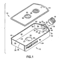
- FIG. 1 is an exploded perspective view of a culture vessel in accordance with the invention.
- FIG. 2 is a perspective view, partly in section, of the vessel of FIG. 1 in the fully assembled condition.
- FIG. 3 is a top plan view of the vessel.
- FIG. 4 is s cross-sectional view taken along line 4-4 in FIG. 3.
- FIG. 5 is a top plan view similar to FIG. 3, but showing a cover with an alternate septum.
- FIG. 6 is an exploded perspective view of an alternate vessel in accordance with the invention.
- FIG. 7 is a top plan view of a vessel similar to the vessel shown in FIG. 6, but showing an alternate septum.
- FIG. 8 is an exploded view of a cap and vessel according to a further embodiment.
- FIG. 9 is a perspective view of an alternate cap.
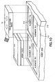
- FIG. 10 is an exploded perspective view of the tissue culture vessel in proximity to a robot deck.
- Tissue culture vessel 10 is a generally hexagonal container with a base 12 , a cover 14 and a cap 16 .
- Base 12 is formed unitarily from a plastic material, and preferably a polystyrene.
- Base 12 includes a substantially planar rectangular bottom wall 18 with a back end 20, first and second sides 22 and 24 and a front end 26 .
- a substantially conically generated trough 27 extends down at a location on bottom wall 18 substantially centrally between back and front ends 20 and 26 and substantially centrally between sides 22 and 24.
- a substantially planar isosceles trapezoidal ramp 28 extends unitarily from front end 26 of bottom wall 18 and is aligned to bottom wall 18 at an obtuse angle of about 150°. Hence, the plane of trapezoidal ramp 28 defines an incline of about 30° when bottom wall 18 is supported on a horizontal surface.
- Front end 26 of bottom wall 18 defines the longer of two parallel bases for trapezoidal ramp 28 .
- Ramp 28 further includes a shorter parallel base end 30 and first and second equal sides 32 and 34 that converge from end 26 toward end 30.
- Bottom supports 35 extend down from bottom wall 18 , as shown in FIG. 4. Bottom ends of the bottom supports 35 define a plane extending substantially parallel to planar portions of bottom wall 18 . The plane defined by the bottom ends of the bottom supports 35 is coplanar with or lower than the bottom of bottom trough 27. Bottom supports 35 also define an outer periphery substantially in the shape of a rectangle.
- Base 12 of vessel 10 includes a substantially rectangular back wall 36 that projects orthogonally from bottom wall 18 at a location adjacent back end 20 of bottom wall 18 .
- Back wall 36 includes a top edge 38 aligned substantially parallel to bottom wall 18 .
- Base 12 also includes first and second substantially parallel rectangular sidewalls 42 and 44 that extend orthogonally from bottom wall 18 at locations adjacent first and second sides 22 and 24 respectively.
- First and second sidewalls 42 and 44 include top edges 46 and 48 respectively that are parallel to bottom wall 18 and substantially coplanar with top edge 38 of back wall 36.
- Sidewalls 42 and 44 have front ends 50 and 52 substantially aligned with opposed sides of front end 26 of bottom wall 18 .
- Base 12 further includes first and second substantially planar transition walls 54 and 56 that converge toward one another from front ends 50 and 52 of first and second sidewalls 42 and 44 respectively.
- First transition wall 54 is substantially trapezoidal and has a top edge 62 that is substantially in the plane defined by top edges 38, 46 and 48.
- Second transition wall 56 also is substantially trapezoidal and includes a top edge 68 substantially in the plane defined by top edges 38, 46, 48 and 62.
- Base 12 of vessel 10 further includes a substantially planar front wall 70 aligned substantially orthogonal to the plane defined by bottom wall 18 .
- Front wall 70 is substantially rectangular and has first and second sides coincident with the front ends of first and second transition walls 54 and 56 respectively.
- Front wall 70 further includes a top edge 74 that extends between top edges 62 and 68 of first and second transition walls 54 and 56 .
- Top edge 74 lies in the plane defined by top edges 38, 46, 48, 62 and 68.
- Base 12 of vessel 10 further includes a generally tubular neck 78 that extends forwardly from front wall 70 .
- Neck 78 includes an open rear end 80 at front wall 70 that communicates with the region of base 12 above bottom wall 18 and ramp 28 .
- Neck 78 further includes a front end 82 and a tubular passage 84 extending between rear end 80 and front end 82 .
- Portions of neck 78 adjacent front end 82 are substantially cylindrically generated and exterior regions of neck 78 adjacent front end 82 include an array of external threads for threaded engagement of cap 16 .
- Cover 14 of vessel 10 is substantially planar and defines a hexagon with a shape that permits cover 14 to rest on top edges 38, 46, 48, 62, 68, and 74 of base 12 or to nest slightly with the vertical walls of base 12 .
- Cover 14 may be secured in position on base 12 by appropriate application of adhesive or by a known bonding technique, such as ultrasonic welding.
- Cover 14 includes a septum aperture 88 at a location aligned with conically generated trough 35 in bottom wall 18, as shown in FIG. 4.
- a self-sealing septum 90 is secured in septum aperture 88.
- Septum 90 is formed from an elastomeric material and is provided with a longitudinal slit 92 aligned substantially along a diameter of aperture 88. Slit 92 may extend entirely through septum 90 or partly through septum 90 and will enable an access device, such as a pipette to be passed through septum 90 for collecting a tissue culture. However, the elastomeric material of septum 90 will reseal upon removal of the access device.
- Cover 14 also is formed with a membrane aperture 94 and a membrane 96 is mounted securely in membrane aperture 94, as shown in FIG. 4.
- Membrane 96 is formed from a material that will permit gas exchange or oxygenation across the otherwise substantially impervious walls of vessel 10 .
- Membrane 96 preferably is sealed initially by a removable sealing layer 98. Sealing layer 98 can be kept in place for those situations where gas exchange is not desired or can be removed at an appropriate time for situations where gas exchange is desired.
- FIG. 5 shows a vessel 10a that is substantially identical to vessel 10 described and illustrated in FIGS. 1-5.
- vessel 10a includes a base 12 identical to the base 12 of vessel 10 and a cap 16 identical to the cap of vessel 10.
- Vessel 10a further includes a cover 14 that is substantially identical to the cover of vessel 10.
- septum aperture 88 of cover 14 is provided with a septum 90a with a cross-cut 92a as shown in FIG. 6.
- Cross-cut 92a may provide a more preferable access for certain types of access devices.
- Culture vessel 10b include a base 12b, a cover 14b and a cap 16.
- Base 12b is very similar to base 12 of culture vessel 10 described and illustrated above.
- bottom wall 18b is provided with an elongate trough 27b that extends substantially continuously between side edges 22b and 24b. All other aspects of base 12b are identical to base 12 , and are not described again.
- Cover 14b is very similar to cover 14 .
- cover 14b includes an elongate generally elliptoid septum aperture 88b and a correspondingly configured septum 90b.
- Septum 90b is provided with an elongate resealable slot 92b disposed and aligned to register substantially with elongate trough 27b in bottom wall 18b.
- Slot 92b enables a plurality of access devices, such as pipettes to be passed simultaneously through slot 92b for obtaining a plurality of tissue or cell cultures simultaneously. Slot 92b then will reseal simultaneously for access again at a later stage. All other aspects of culture vessel 10b are substantially identical to culture vessel 10.
- culture vessel 10c includes a base and a cap substantially identical to the culture vessel 10b.
- the culture vessel in FIG. 7 further includes a cover 14c substantially identical to the cover 14b described and illustrated with respect to FIGS. 6.
- cover 14c includes a septum 90c with a plurality of spaced apart cross-cuts 92c.
- Each cross-cut 92c may be substantially identical to the cross-cuts 92a illustrated in FIG. 5.
- Cross-cuts 92c may facilitate access for certain types of access devices, while enabling simultaneous access by a plurality of such devices.
- FIG. 8 shows a culture vessel 10d similar to culture vessel 10 described and illustrated above.
- culture vessel 10d includes a base 12 and a cap 16 substantially identical to the corresponding parts of the culture vessel 10 described and illustrated with respect to FIGS. 1-5.
- culture vessel 10d has a cover 14d with only one aperture 88d and a threaded cap 100 is mounted in aperture 88d.
- a septum 102 and a membrane 104 are mounted in cap 100.
- Septum 102 and membrane 104 each are substantially semi-circular. However other shapes can be provided, such as a circular septum 102a and an annular membrane 104a, as shown in FIG. 9. These designs enable the type of septum (e.g., straight cut or cross-cut) to be changed for a particular application.
- the type of membrane can be changed for a particular application.
- a solid cap can be engaged in aperture 88d for those situations where no septum or no membrane is desired.
- a cap with only a split septum or only a membrane can be employed.
- culture vessel 10 is well suited for use with automotive robotic devices for accessing the interior of the culture vessel and obtaining samples of cell or tissue cultures.
- culture vessel 10 can be used with a robot deck 110 that has a plurality of rectangular alignment tile recesses 112. Bottom supports 35 of culture vessel 10 are dimensioned to nest in alignment tile 112 to provide a specific arrangement of X,Y coordinates for culture vessel 10 .
Landscapes
- Health & Medical Sciences (AREA)
- Life Sciences & Earth Sciences (AREA)
- Wood Science & Technology (AREA)
- Organic Chemistry (AREA)
- Engineering & Computer Science (AREA)
- Bioinformatics & Cheminformatics (AREA)
- Chemical & Material Sciences (AREA)
- Zoology (AREA)
- Biomedical Technology (AREA)
- Sustainable Development (AREA)
- Microbiology (AREA)
- Biotechnology (AREA)
- Biochemistry (AREA)
- General Engineering & Computer Science (AREA)
- General Health & Medical Sciences (AREA)
- Genetics & Genomics (AREA)
- Clinical Laboratory Science (AREA)
- Molecular Biology (AREA)
- Apparatus Associated With Microorganisms And Enzymes (AREA)
- Packging For Living Organisms, Food Or Medicinal Products That Are Sensitive To Environmental Conditiond (AREA)
Claims (16)
- Gewebekulturbehälter mit einer Basis (12), die eine Bodenwand (18) und mehrere von der Bodenwand nach oben abstehende Seitenwände (36,42,44,70) aufweist, und mit einem Deckel (14), der sich über den Seitenwänden und der Bodenwand (18) gegenüberliegend erstreckt,
dadurch gekennzeichnet, dass
der Deckel (14) mit mindestens einer Durchgangsöffnung und einem sich über der Öffnung erstreckenden Septum (90) versehen ist, um einer medizinischen Vorrichtung den Zugriff auf Innenbereiche des Behälters zu ermöglichen, wobei das Septum aus einem elastomeren Material ausgebildet ist, das nach dem mittels der medizinischen Vorrichtung erfolgenden Zugriff wiederabdichtbar ist. - Gewebekulturbehälter nach Anspruch 1, mit einem hohlen Hals (82), der an einer (70) der Seitenwände ausgebildet ist und eine Verbindung mit Innenbereichen des Behälters ermöglicht, um ein Flüssigmedium in den Behälter hinein oder aus diesem heraus zu gießen, und einem fest an dem Hals angeordneten Verschluss (16) zum selektiven Schließen des Halses.
- Gewebekulturbehälter nach Anspruch 2, bei dem in dem Septum (90) mindestens ein Schlitz (92,92a,92b,92c) ausgebildet ist, der sich mindestens teilweise durch das Septum erstreckt.
- Gewebekulturbehälter nach Anspruch 3, bei dem der mindestens eine Schlitz mindestens zwei Schlitze aufweist, die einander derart schneiden, dass sie einen kreuzförmigen Schnitt in dem Septum bilden.
- Gewebekulturbehälter nach Anspruch 1, bei dem die in dem Deckel ausgebildete Öffnung (88) im Wesentlichen kreisförmig ist.
- Gewebekulturbehälter nach Anspruch 5, bei dem in der Bodenwand (18) der Basis (12) eine der Öffnung des Deckels im Wesentlichen gegenüberliegende Mulde (27) ausgebildet ist, um Flüssigmedium an einer unterhalb des Septums gelegenen Stelle zu sammeln.
- Gewebekulturbehälter nach Anspruch 1, bei dem die Öffnung (88b) eine längliche Öffnung ist.
- Gewebekulturbehälter nach Anspruch 7, bei dem in der Bodenwand (18b) der Basis (12b) eine längliche Mulde (27b) ausgebildet ist, die mit der in dem Deckel vorgesehenen länglichen Öffnung (88b) im Wesentlichen ausgerichtet ist, um in der Mulde Flüssigmedium an Stellen zu sammeln, die mit dem Septum im Wesentlichen ausgerichtet sind.
- Gewebekulturbehälter nach Anspruch 7, bei dem das Septum (90b) mindestens einen zumindest teilweise durch das Septum verlaufenden Schlitz aufweist, um einer medizinischen Vorrichtung den Zugriff zu erleichtern.
- Gewebekulturbehälter nach Anspruch 9, bei dem der mindestens eine Schlitz mehrere Paare einander schneidender Schlitze (92c) an voneinander beabstandeten Stellen entlang des Septums aufweist.
- Gewebekulturbehälter nach Anspruch 1, bei dem das Septum (102, 102a) in einer Kappe (100,100a) gesichert ist und bei dem die Kappe an der in dem Deckel ausgebildeten Öffnung (88d) befestigt ist.
- Gewebekulturbehälter nach Anspruch 11, bei dem an einer (70) der Seitenwände der Basis (12) ein hohler Hals (78) ausgebildet ist, um ein Flüssigmedium in den Behälter hinein oder aus diesem heraus zu gießen.
- Gewebekulturbehälter nach Anspruch 12, ferner mit einem lösbar an dem Hals befestigten Verschluss (16).
- Gewebekulturbehälter nach Anspruch 1, bei dem der Deckel (14) ferner eine Membran (96) zur Ermöglichung von Gasverbindung zwischen dem Inneren des Behälters und der Umgebung aufweist.
- Gewebekulturbehälter nach Anspruch 14, bei dem die Öffnung (88) eine Septumöffnung ist und bei dem der Deckel (14) ferner eine Membranöffnung aufweist, wobei die Membran (96) an der Membranöffnung befestigt ist.
- Gewebekulturbehälter nach Anspruch 1, ferner mit einer Kappe (100, 100a), die an der in dem Deckel (14d) ausgebildeten Öffnung (88d) befestigt ist, wobei das Septum (102,102a) in einem Teil der Kappe angeordnet ist und wobei an einem zweiten Teil der Kappe eine Membran (104,104a) ausgebildet ist, um eine Gasverbindung mit Innenbereichen des Gewebekulturbehälters zu ermöglichen.
Applications Claiming Priority (4)
| Application Number | Priority Date | Filing Date | Title |
|---|---|---|---|
| US50149503P | 2003-09-09 | 2003-09-09 | |
| US501495P | 2003-09-09 | ||
| US922679 | 2004-08-19 | ||
| US10/922,679 US20050074873A1 (en) | 2003-09-09 | 2004-08-19 | Tissue culture vessel |
Publications (2)
| Publication Number | Publication Date |
|---|---|
| EP1514919A1 EP1514919A1 (de) | 2005-03-16 |
| EP1514919B1 true EP1514919B1 (de) | 2007-12-05 |
Family
ID=34139066
Family Applications (1)
| Application Number | Title | Priority Date | Filing Date |
|---|---|---|---|
| EP04020246A Expired - Lifetime EP1514919B1 (de) | 2003-09-09 | 2004-08-26 | Behälter zur Kultivierung von Geweben |
Country Status (5)
| Country | Link |
|---|---|
| US (1) | US20050074873A1 (de) |
| EP (1) | EP1514919B1 (de) |
| JP (1) | JP4714443B2 (de) |
| AT (1) | ATE380237T1 (de) |
| DE (1) | DE602004010474T2 (de) |
Families Citing this family (46)
| Publication number | Priority date | Publication date | Assignee | Title |
|---|---|---|---|---|
| US7078228B2 (en) | 2003-12-31 | 2006-07-18 | Corning Incorporated | Cell cultivating flask |
| JP2008541763A (ja) * | 2005-06-01 | 2008-11-27 | アイアールエム・リミテッド・ライアビリティ・カンパニー | 自動処理のための細胞培養フラスコ、システム及び方法 |
| US20090148941A1 (en) * | 2007-07-30 | 2009-06-11 | Peter Florez | Disposable mini-bioreactor device and method |
| ES2447875T3 (es) | 2007-10-02 | 2014-03-13 | Theranos, Inc. | Dispositivos modulares para punto de cuidados y usos de los mismos |
| CN101978041B (zh) * | 2008-01-25 | 2014-07-30 | 康宁股份有限公司 | 通道受限制的多层细胞培养系统 |
| DE602008002545D1 (de) * | 2008-02-01 | 2010-10-28 | Eppendorf Ag | Kulturplatte mit Klappe zur seitlichen Belüftung |
| US8177082B2 (en) * | 2008-04-18 | 2012-05-15 | Corning Incorporated | Flexible membrane valve for cell culture vessel |
| US8778669B2 (en) | 2009-07-22 | 2014-07-15 | Corning Incorporated | Multilayer tissue culture vessel |
| USD679829S1 (en) | 2010-06-18 | 2013-04-09 | Emd Millipore Corporation | Multilayer cell culture flask |
| USD673292S1 (en) * | 2010-06-18 | 2012-12-25 | Emd Millipore Corporation | Multilayer cell culture flask |
| EP4024029A3 (de) | 2011-01-21 | 2022-09-14 | Labrador Diagnostics LLC | Systeme und verfahren zur maximierung der verwendung einer probe |
| US20140120546A1 (en) * | 2011-06-14 | 2014-05-01 | 3M Innovative Properties Company | Method of processing a sample for analysis |
| US9664702B2 (en) | 2011-09-25 | 2017-05-30 | Theranos, Inc. | Fluid handling apparatus and configurations |
| US9632102B2 (en) | 2011-09-25 | 2017-04-25 | Theranos, Inc. | Systems and methods for multi-purpose analysis |
| US20140170735A1 (en) | 2011-09-25 | 2014-06-19 | Elizabeth A. Holmes | Systems and methods for multi-analysis |
| US9619627B2 (en) | 2011-09-25 | 2017-04-11 | Theranos, Inc. | Systems and methods for collecting and transmitting assay results |
| US8475739B2 (en) | 2011-09-25 | 2013-07-02 | Theranos, Inc. | Systems and methods for fluid handling |
| US9268915B2 (en) | 2011-09-25 | 2016-02-23 | Theranos, Inc. | Systems and methods for diagnosis or treatment |
| US8840838B2 (en) | 2011-09-25 | 2014-09-23 | Theranos, Inc. | Centrifuge configurations |
| US9810704B2 (en) | 2013-02-18 | 2017-11-07 | Theranos, Inc. | Systems and methods for multi-analysis |
| US9250229B2 (en) | 2011-09-25 | 2016-02-02 | Theranos, Inc. | Systems and methods for multi-analysis |
| US10012664B2 (en) | 2011-09-25 | 2018-07-03 | Theranos Ip Company, Llc | Systems and methods for fluid and component handling |
| USD668774S1 (en) * | 2011-10-26 | 2012-10-09 | Becton, Dickinson And Company | Flask with off-center cap orientation |
| USD668772S1 (en) * | 2011-10-26 | 2012-10-09 | Becton, Dickinson And Company | Tilting flask |
| USD668777S1 (en) * | 2011-10-26 | 2012-10-09 | Becton, Dickinson And Company | Diamond shaped flask |
| USD668773S1 (en) * | 2011-10-26 | 2012-10-09 | Becton, Dickinson And Company | Rhombus shaped flask |
| USD668775S1 (en) * | 2011-10-26 | 2012-10-09 | Becton, Dickinson And Company | Octagon shaped flask |
| USD668776S1 (en) * | 2011-10-26 | 2012-10-09 | Becton, Dickinson And Company | Canteen shaped flask |
| US9005550B2 (en) | 2012-10-29 | 2015-04-14 | Corning Incorporated | Multi-layered cell culture vessel with manifold grips |
| DE102013201069A1 (de) | 2013-01-23 | 2014-07-24 | Hamilton Bonaduz Ag | Zellkulturanlage zur Kultivierung adhärenter Zellen sowie Fluid-Versorgungsschnittstelle und Zellkulturbehälter für eine derartige Zellkulturanlage |
| US9790465B2 (en) | 2013-04-30 | 2017-10-17 | Corning Incorporated | Spheroid cell culture well article and methods thereof |
| US10422806B1 (en) | 2013-07-25 | 2019-09-24 | Theranos Ip Company, Llc | Methods for improving assays of biological samples |
| US10519414B2 (en) * | 2013-10-16 | 2019-12-31 | Medikan Inc | Apparatus and method for continuous cell culture |
| WO2016069930A1 (en) | 2014-10-29 | 2016-05-06 | Corning Incorporated | Microwell design and fabrication for generation of cell culture aggregates |
| EP3212759A1 (de) | 2014-10-29 | 2017-09-06 | Corning Incorporated | Zellkultureinsatz |
| JP2016123336A (ja) * | 2014-12-26 | 2016-07-11 | 大日本印刷株式会社 | 細胞培養容器 |
| USD821603S1 (en) * | 2015-06-02 | 2018-06-26 | Tpp Techno Plastic Products Ag | Culture bottle |
| JP2018033387A (ja) * | 2016-08-31 | 2018-03-08 | 株式会社アステック | 細胞培養容器 |
| EP3652290B1 (de) | 2017-07-14 | 2022-05-04 | Corning Incorporated | 3d-zellkulturgefässe für manuellen oder automatischen medienaustausch |
| US11857970B2 (en) | 2017-07-14 | 2024-01-02 | Corning Incorporated | Cell culture vessel |
| JP7197557B2 (ja) * | 2017-07-14 | 2022-12-27 | コーニング インコーポレイテッド | 多孔性支持体を有する細胞培養槽 |
| JP7202080B2 (ja) * | 2018-05-30 | 2023-01-11 | テルモ株式会社 | 細胞処理方法、デバイスおよびシステム |
| WO2020013847A1 (en) | 2018-07-13 | 2020-01-16 | Corning Incorporated | Microcavity dishes with sidewall including liquid medium delivery surface |
| WO2020013845A1 (en) | 2018-07-13 | 2020-01-16 | Corning Incorporated | Cell culture vessels with stabilizer devices |
| CN111065725B (zh) | 2018-07-13 | 2024-03-29 | 康宁股份有限公司 | 包括具有互联的壁的微板的流体装置 |
| CN117203316A (zh) * | 2021-01-11 | 2023-12-08 | Jcr制药股份有限公司 | 细胞培养器以及并列过滤器连接器 |
Family Cites Families (24)
| Publication number | Priority date | Publication date | Assignee | Title |
|---|---|---|---|---|
| US3950227A (en) * | 1970-12-21 | 1976-04-13 | St. John's University | Batch method of establishing and maintaining a controlled aerobic environment for a microbial culture |
| US4301841A (en) * | 1979-10-22 | 1981-11-24 | Kiyoshi Sandow | Multipurpose container |
| JPH044560Y2 (de) * | 1984-10-18 | 1992-02-10 | ||
| US5047347A (en) * | 1987-08-17 | 1991-09-10 | Cline Martin J | Gas permeable culture flask and method for culturing mammalian cells |
| US4839292B1 (en) * | 1987-09-11 | 1994-09-13 | Joseph G Cremonese | Cell culture flask utilizing membrane barrier |
| EP0337677A3 (de) * | 1988-04-11 | 1990-04-04 | Costar Corporation | Entlüftungskappe |
| JPH02127199U (de) * | 1989-03-28 | 1990-10-19 | ||
| US5272084A (en) * | 1991-12-18 | 1993-12-21 | Corning Incorporated | Cell culture vessels having interior ridges and method for cultivating cells in same |
| US5693537A (en) * | 1994-06-28 | 1997-12-02 | Wilson; John R. | Compartmentalized tissue culture flask |
| DE69534132T2 (de) * | 1994-06-28 | 2005-09-29 | Wilson Wolf Corp., New Brighton | Zellkulturflasche mit mehreren kammern |
| CA2175626C (en) * | 1995-05-18 | 1999-08-03 | Timothy A. Stevens | Tissue culture flask |
| WO1996039533A1 (en) * | 1995-06-05 | 1996-12-12 | Akzo Nobel N.V. | Device and method for detecting microorganisms |
| US5801054A (en) * | 1996-09-19 | 1998-09-01 | The United States Of America As Represented By The Secretary Of The Air Force | Cell culture vessel with self-maintained atmosphere |
| US5863792A (en) * | 1997-03-19 | 1999-01-26 | Becton Dickson And Company | Culture vessel assembly |
| GB9803362D0 (en) * | 1998-02-17 | 1998-04-15 | Cellon Sa | A cell culture vessel |
| EP1183187A4 (de) * | 1998-10-21 | 2004-03-17 | Wei K Hsu | Sterilisierbares zuchtsystem mit getrennt anbringbaren mikrofiltrationsmembran |
| US6455310B1 (en) * | 1999-03-23 | 2002-09-24 | Biocrystal Ltd. | Cell culture apparatus and method for culturing cells |
| US6410309B1 (en) * | 1999-03-23 | 2002-06-25 | Biocrystal Ltd | Cell culture apparatus and methods of use |
| US6569675B2 (en) * | 2000-06-16 | 2003-05-27 | Corning Incorporated | Cell cultivating flask and method for using the cell cultivating flask |
| US20020039785A1 (en) * | 2000-10-04 | 2002-04-04 | Schroeder Kirk S. | Cell-culture vessel |
| US6673595B2 (en) * | 2001-08-27 | 2004-01-06 | Biocrystal, Ltd | Automated cell management system for growth and manipulation of cultured cells |
| US6730510B2 (en) * | 2002-07-02 | 2004-05-04 | Organogenesis, Inc. | Culture dish and bioreactor system |
| US20040029266A1 (en) * | 2002-08-09 | 2004-02-12 | Emilio Barbera-Guillem | Cell and tissue culture device |
| DE60224673T2 (de) * | 2002-10-04 | 2009-01-15 | Becton Dickinson And Co. | Kulturflasche |
-
2004
- 2004-08-19 US US10/922,679 patent/US20050074873A1/en not_active Abandoned
- 2004-08-26 EP EP04020246A patent/EP1514919B1/de not_active Expired - Lifetime
- 2004-08-26 DE DE602004010474T patent/DE602004010474T2/de not_active Expired - Lifetime
- 2004-08-26 AT AT04020246T patent/ATE380237T1/de active
- 2004-08-27 JP JP2004248904A patent/JP4714443B2/ja not_active Expired - Fee Related
Also Published As
| Publication number | Publication date |
|---|---|
| US20050074873A1 (en) | 2005-04-07 |
| DE602004010474D1 (de) | 2008-01-17 |
| JP4714443B2 (ja) | 2011-06-29 |
| DE602004010474T2 (de) | 2008-11-20 |
| ATE380237T1 (de) | 2007-12-15 |
| JP2005080660A (ja) | 2005-03-31 |
| EP1514919A1 (de) | 2005-03-16 |
Similar Documents
| Publication | Publication Date | Title |
|---|---|---|
| EP1514919B1 (de) | Behälter zur Kultivierung von Geweben | |
| US5554536A (en) | Biological analysis device having improved contamination prevention | |
| DE69325567T2 (de) | Kulturgefäss | |
| US6811752B2 (en) | Device having microchambers and microfluidics | |
| US7820433B2 (en) | Culture dish for culturing biological cells | |
| US9751084B2 (en) | Biological culture assembly | |
| EP2473283B1 (de) | Tiefbrunnenplattensystem mit Deckel | |
| ES2259085T3 (es) | Aparato de ensayo multipocillo. | |
| EP0591436B1 (de) | Vorrichtung zur kultivierung und manipulierung von zellen | |
| US7854896B2 (en) | Closed system storage plates | |
| CN111151175B (zh) | 多孔分离设备和试剂递送装置 | |
| ES2294244T3 (es) | Microplaca con cubierta inferior de bandeja protectora. | |
| EP3689467A1 (de) | Einspaltiges mikroplattensystem und träger zur analyse biologischer proben | |
| JP2573795B2 (ja) | 生体外で組織培養物を成長させる装置 | |
| AU2003244195A1 (en) | Multi-well device | |
| US11788043B2 (en) | Cell culture plate, assembly and methods of use | |
| US7309603B2 (en) | Multiwell plate lid with vents | |
| US20040141895A1 (en) | Protein crystallography hanging drop multiwell plate | |
| US6284531B1 (en) | Multi-compartment device for cultivating microorganisms | |
| WO2010124663A2 (en) | Method for adding, removing or exchange a liquid medium in culturing biological cells and culture device | |
| HK1237709A1 (en) | Multi-well separation apparatus and reagent delivery device |
Legal Events
| Date | Code | Title | Description |
|---|---|---|---|
| PUAI | Public reference made under article 153(3) epc to a published international application that has entered the european phase |
Free format text: ORIGINAL CODE: 0009012 |
|
| AK | Designated contracting states |
Kind code of ref document: A1 Designated state(s): AT BE BG CH CY CZ DE DK EE ES FI FR GB GR HU IE IT LI LU MC NL PL PT RO SE SI SK TR |
|
| AX | Request for extension of the european patent |
Extension state: AL HR LT LV MK |
|
| 17P | Request for examination filed |
Effective date: 20050906 |
|
| AKX | Designation fees paid |
Designated state(s): AT BE BG CH CY CZ DE DK EE ES FI FR GB GR HU IE IT LI LU MC NL PL PT RO SE SI SK TR |
|
| 17Q | First examination report despatched |
Effective date: 20060804 |
|
| GRAP | Despatch of communication of intention to grant a patent |
Free format text: ORIGINAL CODE: EPIDOSNIGR1 |
|
| GRAS | Grant fee paid |
Free format text: ORIGINAL CODE: EPIDOSNIGR3 |
|
| GRAA | (expected) grant |
Free format text: ORIGINAL CODE: 0009210 |
|
| AK | Designated contracting states |
Kind code of ref document: B1 Designated state(s): AT BE BG CH CY CZ DE DK EE ES FI FR GB GR HU IE IT LI LU MC NL PL PT RO SE SI SK TR |
|
| REG | Reference to a national code |
Ref country code: IE Ref legal event code: FG4D |
|
| REG | Reference to a national code |
Ref country code: CH Ref legal event code: EP |
|
| REF | Corresponds to: |
Ref document number: 602004010474 Country of ref document: DE Date of ref document: 20080117 Kind code of ref document: P |
|
| REG | Reference to a national code |
Ref country code: CH Ref legal event code: NV Representative=s name: ISLER & PEDRAZZINI AG |
|
| PG25 | Lapsed in a contracting state [announced via postgrant information from national office to epo] |
Ref country code: SE Free format text: LAPSE BECAUSE OF FAILURE TO SUBMIT A TRANSLATION OF THE DESCRIPTION OR TO PAY THE FEE WITHIN THE PRESCRIBED TIME-LIMIT Effective date: 20080305 Ref country code: ES Free format text: LAPSE BECAUSE OF FAILURE TO SUBMIT A TRANSLATION OF THE DESCRIPTION OR TO PAY THE FEE WITHIN THE PRESCRIBED TIME-LIMIT Effective date: 20080316 Ref country code: NL Free format text: LAPSE BECAUSE OF FAILURE TO SUBMIT A TRANSLATION OF THE DESCRIPTION OR TO PAY THE FEE WITHIN THE PRESCRIBED TIME-LIMIT Effective date: 20071205 |
|
| PG25 | Lapsed in a contracting state [announced via postgrant information from national office to epo] |
Ref country code: PL Free format text: LAPSE BECAUSE OF FAILURE TO SUBMIT A TRANSLATION OF THE DESCRIPTION OR TO PAY THE FEE WITHIN THE PRESCRIBED TIME-LIMIT Effective date: 20071205 Ref country code: FI Free format text: LAPSE BECAUSE OF FAILURE TO SUBMIT A TRANSLATION OF THE DESCRIPTION OR TO PAY THE FEE WITHIN THE PRESCRIBED TIME-LIMIT Effective date: 20071205 Ref country code: SI Free format text: LAPSE BECAUSE OF FAILURE TO SUBMIT A TRANSLATION OF THE DESCRIPTION OR TO PAY THE FEE WITHIN THE PRESCRIBED TIME-LIMIT Effective date: 20071205 |
|
| NLV1 | Nl: lapsed or annulled due to failure to fulfill the requirements of art. 29p and 29m of the patents act | ||
| PG25 | Lapsed in a contracting state [announced via postgrant information from national office to epo] |
Ref country code: CZ Free format text: LAPSE BECAUSE OF FAILURE TO SUBMIT A TRANSLATION OF THE DESCRIPTION OR TO PAY THE FEE WITHIN THE PRESCRIBED TIME-LIMIT Effective date: 20071205 |
|
| PG25 | Lapsed in a contracting state [announced via postgrant information from national office to epo] |
Ref country code: BE Free format text: LAPSE BECAUSE OF FAILURE TO SUBMIT A TRANSLATION OF THE DESCRIPTION OR TO PAY THE FEE WITHIN THE PRESCRIBED TIME-LIMIT Effective date: 20071205 Ref country code: RO Free format text: LAPSE BECAUSE OF FAILURE TO SUBMIT A TRANSLATION OF THE DESCRIPTION OR TO PAY THE FEE WITHIN THE PRESCRIBED TIME-LIMIT Effective date: 20071205 Ref country code: SK Free format text: LAPSE BECAUSE OF FAILURE TO SUBMIT A TRANSLATION OF THE DESCRIPTION OR TO PAY THE FEE WITHIN THE PRESCRIBED TIME-LIMIT Effective date: 20071205 |
|
| PG25 | Lapsed in a contracting state [announced via postgrant information from national office to epo] |
Ref country code: PT Free format text: LAPSE BECAUSE OF FAILURE TO SUBMIT A TRANSLATION OF THE DESCRIPTION OR TO PAY THE FEE WITHIN THE PRESCRIBED TIME-LIMIT Effective date: 20080505 |
|
| EN | Fr: translation not filed | ||
| PLBE | No opposition filed within time limit |
Free format text: ORIGINAL CODE: 0009261 |
|
| STAA | Information on the status of an ep patent application or granted ep patent |
Free format text: STATUS: NO OPPOSITION FILED WITHIN TIME LIMIT |
|
| PG25 | Lapsed in a contracting state [announced via postgrant information from national office to epo] |
Ref country code: DK Free format text: LAPSE BECAUSE OF FAILURE TO SUBMIT A TRANSLATION OF THE DESCRIPTION OR TO PAY THE FEE WITHIN THE PRESCRIBED TIME-LIMIT Effective date: 20071205 |
|
| 26N | No opposition filed |
Effective date: 20080908 |
|
| PG25 | Lapsed in a contracting state [announced via postgrant information from national office to epo] |
Ref country code: GR Free format text: LAPSE BECAUSE OF FAILURE TO SUBMIT A TRANSLATION OF THE DESCRIPTION OR TO PAY THE FEE WITHIN THE PRESCRIBED TIME-LIMIT Effective date: 20080306 |
|
| PG25 | Lapsed in a contracting state [announced via postgrant information from national office to epo] |
Ref country code: MC Free format text: LAPSE BECAUSE OF NON-PAYMENT OF DUE FEES Effective date: 20080831 |
|
| PG25 | Lapsed in a contracting state [announced via postgrant information from national office to epo] |
Ref country code: BG Free format text: LAPSE BECAUSE OF FAILURE TO SUBMIT A TRANSLATION OF THE DESCRIPTION OR TO PAY THE FEE WITHIN THE PRESCRIBED TIME-LIMIT Effective date: 20080305 Ref country code: EE Free format text: LAPSE BECAUSE OF FAILURE TO SUBMIT A TRANSLATION OF THE DESCRIPTION OR TO PAY THE FEE WITHIN THE PRESCRIBED TIME-LIMIT Effective date: 20071205 Ref country code: FR Free format text: LAPSE BECAUSE OF FAILURE TO SUBMIT A TRANSLATION OF THE DESCRIPTION OR TO PAY THE FEE WITHIN THE PRESCRIBED TIME-LIMIT Effective date: 20081003 |
|
| PG25 | Lapsed in a contracting state [announced via postgrant information from national office to epo] |
Ref country code: IE Free format text: LAPSE BECAUSE OF NON-PAYMENT OF DUE FEES Effective date: 20080826 Ref country code: CY Free format text: LAPSE BECAUSE OF FAILURE TO SUBMIT A TRANSLATION OF THE DESCRIPTION OR TO PAY THE FEE WITHIN THE PRESCRIBED TIME-LIMIT Effective date: 20071205 |
|
| PG25 | Lapsed in a contracting state [announced via postgrant information from national office to epo] |
Ref country code: HU Free format text: LAPSE BECAUSE OF FAILURE TO SUBMIT A TRANSLATION OF THE DESCRIPTION OR TO PAY THE FEE WITHIN THE PRESCRIBED TIME-LIMIT Effective date: 20080606 Ref country code: LU Free format text: LAPSE BECAUSE OF NON-PAYMENT OF DUE FEES Effective date: 20080826 |
|
| PG25 | Lapsed in a contracting state [announced via postgrant information from national office to epo] |
Ref country code: TR Free format text: LAPSE BECAUSE OF FAILURE TO SUBMIT A TRANSLATION OF THE DESCRIPTION OR TO PAY THE FEE WITHIN THE PRESCRIBED TIME-LIMIT Effective date: 20071205 |
|
| REG | Reference to a national code |
Ref country code: DE Ref legal event code: R082 Ref document number: 602004010474 Country of ref document: DE Representative=s name: VON KREISLER SELTING WERNER, DE |
|
| REG | Reference to a national code |
Ref country code: DE Ref legal event code: R081 Ref document number: 602004010474 Country of ref document: DE Owner name: CORNING INCORPORATED, US Free format text: FORMER OWNER: BECTON DICKINSON AND CO., FRANKLIN LAKES, US Effective date: 20130128 Ref country code: DE Ref legal event code: R082 Ref document number: 602004010474 Country of ref document: DE Representative=s name: VON KREISLER SELTING WERNER, DE Effective date: 20130128 Ref country code: DE Ref legal event code: R081 Ref document number: 602004010474 Country of ref document: DE Owner name: CORNING INCORPORATED, CORNING, US Free format text: FORMER OWNER: BECTON DICKINSON AND CO., FRANKLIN LAKES, N.J., US Effective date: 20130128 Ref country code: DE Ref legal event code: R082 Ref document number: 602004010474 Country of ref document: DE Representative=s name: VON KREISLER SELTING WERNER - PARTNERSCHAFT VO, DE Effective date: 20130128 |
|
| REG | Reference to a national code |
Ref country code: GB Ref legal event code: 732E Free format text: REGISTERED BETWEEN 20130321 AND 20130327 |
|
| REG | Reference to a national code |
Ref country code: CH Ref legal event code: PUE Owner name: CORNING INCORPORATED, US Free format text: FORMER OWNER: BECTON, DICKINSON AND COMPANY, US |
|
| PGFP | Annual fee paid to national office [announced via postgrant information from national office to epo] |
Ref country code: CH Payment date: 20130828 Year of fee payment: 10 Ref country code: DE Payment date: 20130828 Year of fee payment: 10 Ref country code: AT Payment date: 20130801 Year of fee payment: 10 |
|
| PGFP | Annual fee paid to national office [announced via postgrant information from national office to epo] |
Ref country code: GB Payment date: 20130827 Year of fee payment: 10 |
|
| PGFP | Annual fee paid to national office [announced via postgrant information from national office to epo] |
Ref country code: IT Payment date: 20130822 Year of fee payment: 10 |
|
| REG | Reference to a national code |
Ref country code: DE Ref legal event code: R119 Ref document number: 602004010474 Country of ref document: DE |
|
| REG | Reference to a national code |
Ref country code: CH Ref legal event code: PL |
|
| REG | Reference to a national code |
Ref country code: AT Ref legal event code: MM01 Ref document number: 380237 Country of ref document: AT Kind code of ref document: T Effective date: 20140826 |
|
| GBPC | Gb: european patent ceased through non-payment of renewal fee |
Effective date: 20140826 |
|
| PG25 | Lapsed in a contracting state [announced via postgrant information from national office to epo] |
Ref country code: LI Free format text: LAPSE BECAUSE OF NON-PAYMENT OF DUE FEES Effective date: 20140831 Ref country code: IT Free format text: LAPSE BECAUSE OF NON-PAYMENT OF DUE FEES Effective date: 20140826 Ref country code: CH Free format text: LAPSE BECAUSE OF NON-PAYMENT OF DUE FEES Effective date: 20140831 |
|
| REG | Reference to a national code |
Ref country code: DE Ref legal event code: R119 Ref document number: 602004010474 Country of ref document: DE Effective date: 20150303 |
|
| PG25 | Lapsed in a contracting state [announced via postgrant information from national office to epo] |
Ref country code: AT Free format text: LAPSE BECAUSE OF NON-PAYMENT OF DUE FEES Effective date: 20140826 |
|
| PG25 | Lapsed in a contracting state [announced via postgrant information from national office to epo] |
Ref country code: GB Free format text: LAPSE BECAUSE OF NON-PAYMENT OF DUE FEES Effective date: 20140826 Ref country code: DE Free format text: LAPSE BECAUSE OF NON-PAYMENT OF DUE FEES Effective date: 20150303 |