EP1514368B1 - Analyseur de signaux et procede pour afficher des puissances de canaux code avec diversite a l'emission orthogonale - Google Patents
Analyseur de signaux et procede pour afficher des puissances de canaux code avec diversite a l'emission orthogonale Download PDFInfo
- Publication number
- EP1514368B1 EP1514368B1 EP03727416A EP03727416A EP1514368B1 EP 1514368 B1 EP1514368 B1 EP 1514368B1 EP 03727416 A EP03727416 A EP 03727416A EP 03727416 A EP03727416 A EP 03727416A EP 1514368 B1 EP1514368 B1 EP 1514368B1
- Authority
- EP
- European Patent Office
- Prior art keywords
- code
- ant2
- ant1
- channels
- antenna
- Prior art date
- Legal status (The legal status is an assumption and is not a legal conclusion. Google has not performed a legal analysis and makes no representation as to the accuracy of the status listed.)
- Expired - Lifetime
Links
- 238000000034 method Methods 0.000 title claims description 8
- 101150092978 Slc25a4 gene Proteins 0.000 claims description 43
- 101150041689 SLC25A5 gene Proteins 0.000 claims description 38
- 238000011156 evaluation Methods 0.000 claims description 8
- 108010003272 Hyaluronate lyase Proteins 0.000 description 5
- 230000008901 benefit Effects 0.000 description 2
- 238000010586 diagram Methods 0.000 description 2
- 238000005259 measurement Methods 0.000 description 2
- 230000001174 ascending effect Effects 0.000 description 1
- 230000005540 biological transmission Effects 0.000 description 1
- 238000011161 development Methods 0.000 description 1
- 230000018109 developmental process Effects 0.000 description 1
- 238000013507 mapping Methods 0.000 description 1
- 239000011159 matrix material Substances 0.000 description 1
Images

Classifications
-
- H—ELECTRICITY
- H04—ELECTRIC COMMUNICATION TECHNIQUE
- H04B—TRANSMISSION
- H04B17/00—Monitoring; Testing
- H04B17/30—Monitoring; Testing of propagation channels
- H04B17/309—Measuring or estimating channel quality parameters
- H04B17/318—Received signal strength
- H04B17/327—Received signal code power [RSCP]
-
- H—ELECTRICITY
- H04—ELECTRIC COMMUNICATION TECHNIQUE
- H04B—TRANSMISSION
- H04B7/00—Radio transmission systems, i.e. using radiation field
- H04B7/02—Diversity systems; Multi-antenna system, i.e. transmission or reception using multiple antennas
- H04B7/04—Diversity systems; Multi-antenna system, i.e. transmission or reception using multiple antennas using two or more spaced independent antennas
- H04B7/06—Diversity systems; Multi-antenna system, i.e. transmission or reception using multiple antennas using two or more spaced independent antennas at the transmitting station
- H04B7/0613—Diversity systems; Multi-antenna system, i.e. transmission or reception using multiple antennas using two or more spaced independent antennas at the transmitting station using simultaneous transmission
- H04B7/0667—Diversity systems; Multi-antenna system, i.e. transmission or reception using multiple antennas using two or more spaced independent antennas at the transmitting station using simultaneous transmission of delayed versions of same signal
-
- H—ELECTRICITY
- H04—ELECTRIC COMMUNICATION TECHNIQUE
- H04B—TRANSMISSION
- H04B7/00—Radio transmission systems, i.e. using radiation field
- H04B7/02—Diversity systems; Multi-antenna system, i.e. transmission or reception using multiple antennas
- H04B7/04—Diversity systems; Multi-antenna system, i.e. transmission or reception using multiple antennas using two or more spaced independent antennas
- H04B7/06—Diversity systems; Multi-antenna system, i.e. transmission or reception using multiple antennas using two or more spaced independent antennas at the transmitting station
- H04B7/0613—Diversity systems; Multi-antenna system, i.e. transmission or reception using multiple antennas using two or more spaced independent antennas at the transmitting station using simultaneous transmission
- H04B7/0678—Diversity systems; Multi-antenna system, i.e. transmission or reception using multiple antennas using two or more spaced independent antennas at the transmitting station using simultaneous transmission using different spreading codes between antennas
Definitions
- the invention relates to a signal analyzer and a method for displaying powers of code channels of a CDMA (code Division Multiple A ccess) signal.
- CDMA code Division Multiple A ccess
- a signal analyzer and a method for displaying performances of code channels to provide for CDMA signals with Transmit Diversity is the performance of the code channels for each one antenna are completely displayed.
- the object is achieved by the method according to claim 1 and the signal analyzer according to claim 3 solved.
- orthogonal transmit diversity the signal of a active code channel distributed to at least two antennas. For this purpose, two orthogonal codes are generated, which are the next higher code class are to be taken. The lower one Code channel number is then assigned to antenna 1, the higher code channel number antenna 2.
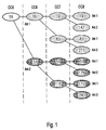
- a section of a code tree is schematic shown.
- the individual Code classes which are labeled CC5 for code class 5, CC6 for code class 6, etc. are.
- the code channel with the number 19 of the code class CC5 be active.
- the actually in Code class CC5 active channel 19 is therefore in the Code class CC6 as code channel 19 on antenna Ant1 and as Code channel 51 is sent to antenna Ant2.
- the education law of the code channel numbers is as follows:
- the code channel number for antenna Ant1 is the basic code channel number.
- the code channel number for antenna Ant2 is the base code channel number plus base spreading factor.
- an antenna accurate representation includes for antenna Ant2 the code channels 51, 179, 115 and 243, which result from the code branch, the code class CC6 in the code channel 51 has its origin.
- FIG. 2 is schematically the assignment for the selected Example of FIG. 1 shown.
- the performances of the code channels are shown in FIG. as it results directly from the measurement in code class CC8 result.
- For antenna Ant2 is additionally for better comprehension Code channel number, as in code class CC8 of FIG. 1 is shown, applied.
- each belonging to the antenna Ant1 Code channels is shown, according to the invention actually the antenna Assigned to Ant1.
- the gray in the upper half of Fig. 2 represented code channels that actually the antenna Ant2 assign are, according to the invention accordingly in the lower half right at the Antenna Ant2 displayed correctly.
- Fig. 3 is a block diagram is shown, a Signal analyzer 1 according to the invention, with the Help, for example, the signal of a base station. 2 to be analyzed.
- the signal analyzer 1 comprises a Evaluation device 3 and a display device 4.
- a CDMA signal 5 is via an input terminal 6 the Signal analyzer 1 supplied.
- the CDMA signal 5 via a Switch 8, which is connected to the signal analyzer 1 is, received.
- the direct connection line, over which the signal 5 is transmitted could also be a Antenna at the input terminal 6, which the from the Base station 2 via the antennas Ant1, Ant2 radiated CDMA signal 5, or a combiner receiving the Summed signal generated by antenna Ant1 and antenna Ant2, be connected.
- the power for the Code channels of that code class determines which the Next to the code class to be displayed is the for example, determined by an operator. in the As described above, this would be the code class CC8 for the code class CC7 to be displayed.
- the evaluation device 3 is a picture of the measured power generated by the code channels, where off Finally, this figure shows the code channels which the corresponding antenna Ant1 or antenna Ant2 assign are to be determined.
- the thus determined achievements of the code channels for the Antenna Ant1 or for the antenna Ant2 are then fed via a connection 9 of the display device 4.
- On the display device 4 is then preferably a Bar chart showing the services of the Code channels to the code class to be displayed, in present case of the code class CC7, wherein the Display device 4 preferably only antenna Ant1 or antenna Ant2 represents.
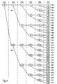
- Fig. 4 is for an active code channel 2 of Code class 2, the resulting code tree shown. Due to the orthogonal transmit diversity, the active code channel 2 of the code class CC2 via an antenna Ant1 and an antenna Ant2 sent, the antenna Ant1 contains the code channel 2 of the code class CC3 and the Antenna 2 is the code channel 6 of the code class CC3. At a Representation of the measured power of the individual code channels would accordingly for the antenna Ant1 respectively to show the performance of the code channels which of the code channel 2 of the code class CC3 go out. In the Fig. 4, this is the entire top half of the illustrated Code tree.
- the Performance of the individual code channels in the code class CC7 be measured. This results from the assignment the individual code channel numbers to antenna Ant1 or Antenna Ant2 that only every second code channel number of the Code class CC7 is assigned to the antenna Ant1.
- the channels are sorted according to the invention that on the X-axis ascending code channel numbers are arranged.
- code class CC7 the channel numbers 0 to 127 exist, where the code channel numbers 0 to 63 of the antenna Ant1 are assigned and the code channel number 64 to 127 of the Antenna Ant2.
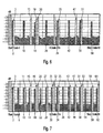
- the resulting representation on the display device 4 of the signal analyzer 1 is in Fig. 6, wherein it is assumed that for the Antenna Ant2 each only noise power is measurable. Without Implementation of the code channel interchange according to the invention is therefore only for the code channels 2, 10, 18, 26, 34, 42, 50 and 58, which are shown dark in FIG. 6, a power of an active code channel measurable.
- the code branch of the antenna Ant1 from FIG. 4 results on the other hand, that services included in the code channels 66, 74, 82, 90, etc. are measurable, also the antenna Ant1 are assigned.
- FIG. 7 results on the display device 4, the originally the Antenna Ant2 associated code channels 66, 74, 82, etc. now mapped into the range of lower code channel numbers were antenna-correct for the antenna Ant1 being represented.
- Fig. 7 are therefore services for the code channels 2, 6, 10, 14, 18, 22, 26 and so on detect.
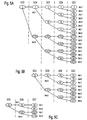
- FIGS. 5A, 5B and 5C show further details Code trees for the active code channel 3 of the code class CC3, the code code 15 active code channel CC4 and the active code channel 20 of the code class CC5 shown.
- the in each case in the code class CC7 measured powers for Antenna Ant1 are in accordance with the above in detail explained example of Fig. 4 in Fig. 6 also shown. For better distinction, they are shown code channels 3, 15, 19, 20, etc. light gray shown.
- Fig. 7 again shows an antenna correctly Representation of all measured with respect to an antenna Ant1 Services in the code channels.
- the antenna Ant2 each inactive is. In practice, however, is usually also antenna Ant2 to Contribute data transmission.
- resulting power of the antenna Ant2 not through the performance of the antenna Ant1 in the code channel exchange is overwritten, is previously one corresponding storage of originating from antenna Ant2 Services required.
- Such storage can z. B. by the image of the performance of each code channels before the code exchange into one Memory can be achieved.
Landscapes
- Engineering & Computer Science (AREA)
- Quality & Reliability (AREA)
- Physics & Mathematics (AREA)
- Electromagnetism (AREA)
- Computer Networks & Wireless Communication (AREA)
- Signal Processing (AREA)
- Mobile Radio Communication Systems (AREA)
Claims (5)
- Procédé pour afficher les puissances des canaux de codage d'un signal en mode d'accès multiple par répartition en code, AMRC (Code Division Multiple Access, CDMA), qui est émis en diversité de transmission orthogonale (Orthogonal Transmit Diversity, OTD), moyennant quoi le signal est émis par l'intermédiaire d'au moins une parmi au moins deux antennes (Ant1, Ant2), comportant les étapes de procédé qui suivent, consistant à:recevoir le signal AMRC;définir une classe de codage (CC6, CC7) pour la représentation de la puissance des canaux de codage individuels;déterminer les puissances des canaux de codage individuels (19, 147, 83, ...) dans la classe de codage immédiatement supérieure (CC7, CC8) en relation avec la classe de codage (CC6, CC7) définie;associer les puissances des canaux de codage individuels (19, 147, 83, ...) à l'antenne correspondante (Ant1, Ant2) en fonction de la diversité de transmission orthogonale dans la classe de codage (CC6, CC7) définie;exécuter une substitution des canaux de codage conformément à l'association effective des antennes (Ant1, Ant2) en relation avec les classes de codage (CC2, CC3, CC4, CC5) des canaux de codage effectivement actifs (2, 3, 15, 20); etreprésenter les puissances des canaux de codage substitués en rapport avec au moins une antenne (Ant1, Ant2).
- Procédé selon la revendication 1,
caractérisé en ce que, en vue de la représentation de la puissance des canaux de codage effectivement actifs (2, 3, 15, 20), la puissance des branches de codage relevant des canaux de codage (2, 3, 15, 20) respectivement actifs est représentée de façon compacte. - Analyseur de signaux pour analyser des signaux AMRC (CDMA) en diversité de transmission orthogonale (OTD) en rapport avec au moins deux antennes (Ant1, Ant2), moyennant quoi le signal AMRC (5) est émis par l'intermédiaire d'au moins une parmi au moins deux antennes (Ant1, Ant2), comportant
un dispositif d'évaluation (3), qui détecte les puissances des canaux de codage individuels et associe les canaux de codage détectés dans la classe de codage immédiatement supérieure (CC7, CC8) en relation avec la classe de codage (CC6, CC7) définie à représenter, répartis en fonction de la diversité de transmission orthogonale sur les antennes correspondantes (Ant1, Ant2), respectivement à l'antenne (Ant1, Ant2) qui, compte tenu de la diversité de transmission orthogonale, est effectivement active en relation avec le canal de codage actif,
ainsi qu'un dispositif d'affichage (4), qui affiche la puissance des canaux de codage associés moyennant le dispositif d'évaluation (3) aux antennes (Ant1; Ant2). - Analyseur de signaux selon la revendication 3, caractérisé en ce que le dispositif d'affichage (4) représente les puissances des canaux de codage en rapport avec respectivement seulement une antenne active (Ant1; Ant2).
- Analyseur de signaux selon la revendication 3 ou 4, caractérisé en ce que le dispositif d'affichage (4) représente les puissances des canaux de codage actifs en tant que somme des puissances des branches de codage individuelles.
Applications Claiming Priority (3)
| Application Number | Priority Date | Filing Date | Title |
|---|---|---|---|
| DE10226639A DE10226639A1 (de) | 2002-06-14 | 2002-06-14 | Signalanalysator und Verfahren zum Anzeigen von Leistungen von Code-Kanälen bei orthogonaler Transmit Diversity |
| DE10226639 | 2002-06-14 | ||
| PCT/EP2003/004567 WO2003107567A1 (fr) | 2002-06-14 | 2003-04-30 | Analyseur de signaux et procede pour afficher des puissances de canaux code avec diversite a l'emission orthogonale |
Publications (2)
| Publication Number | Publication Date |
|---|---|
| EP1514368A1 EP1514368A1 (fr) | 2005-03-16 |
| EP1514368B1 true EP1514368B1 (fr) | 2005-07-20 |
Family
ID=29594534
Family Applications (1)
| Application Number | Title | Priority Date | Filing Date |
|---|---|---|---|
| EP03727416A Expired - Lifetime EP1514368B1 (fr) | 2002-06-14 | 2003-04-30 | Analyseur de signaux et procede pour afficher des puissances de canaux code avec diversite a l'emission orthogonale |
Country Status (5)
| Country | Link |
|---|---|
| US (1) | US7239616B2 (fr) |
| EP (1) | EP1514368B1 (fr) |
| JP (1) | JP4291266B2 (fr) |
| DE (2) | DE10226639A1 (fr) |
| WO (1) | WO2003107567A1 (fr) |
Family Cites Families (10)
| Publication number | Priority date | Publication date | Assignee | Title |
|---|---|---|---|---|
| US6173005B1 (en) * | 1997-09-04 | 2001-01-09 | Motorola, Inc. | Apparatus and method for transmitting signals in a communication system |
| US6219340B1 (en) * | 1998-05-08 | 2001-04-17 | Agilent Technologies Inc. | Display of code power in all symbol rates in a single screen for code-division multiple access signals employing layered orthogonal codes |
| JP2000216754A (ja) * | 1998-11-18 | 2000-08-04 | Advantest Corp | W―cdma解析装置、w―cdma解析結果表示方法およびw―cdma解析結果表示プログラムを記録した記録媒体 |
| EP1168654B1 (fr) * | 2000-06-28 | 2006-08-16 | Samsung Electronics Co. Ltd. | Moyens de mésure de puissance d'un canal pilote pour une station mobile dans un système asynchrone à AMRC |
| US6879576B1 (en) * | 2000-09-06 | 2005-04-12 | Qualcomm Incorporated | Method and apparatus for processing a physical channel with partial transport format information |
| DE10056258B4 (de) * | 2000-11-14 | 2004-02-26 | Rohde & Schwarz Gmbh & Co. Kg | Verfahren zur Bestimmung und zur Anzeige der Leistungsanteile der Codes eines CDMA-Signals |
| US7386076B2 (en) * | 2001-03-29 | 2008-06-10 | Texas Instruments Incorporated | Space time encoded wireless communication system with multipath resolution receivers |
| US6850238B2 (en) * | 2001-07-31 | 2005-02-01 | Tektronix, Inc. | Display of code power levels and relationships of multiple spreading factor orthogonal codes in a CDMA signal |
| US7184406B2 (en) * | 2001-09-28 | 2007-02-27 | Tektronix, Inc. | Visualization of active codes, their spreading factors and power levels, in a code domain power display |
| US8699505B2 (en) * | 2002-05-31 | 2014-04-15 | Qualcomm Incorporated | Dynamic channelization code allocation |
-
2002
- 2002-06-14 DE DE10226639A patent/DE10226639A1/de not_active Withdrawn
-
2003
- 2003-04-30 JP JP2004514248A patent/JP4291266B2/ja not_active Expired - Lifetime
- 2003-04-30 EP EP03727416A patent/EP1514368B1/fr not_active Expired - Lifetime
- 2003-04-30 DE DE50300827T patent/DE50300827D1/de not_active Expired - Lifetime
- 2003-04-30 WO PCT/EP2003/004567 patent/WO2003107567A1/fr not_active Ceased
- 2003-04-30 US US10/517,296 patent/US7239616B2/en not_active Expired - Lifetime
Also Published As
| Publication number | Publication date |
|---|---|
| DE10226639A1 (de) | 2003-12-24 |
| EP1514368A1 (fr) | 2005-03-16 |
| US7239616B2 (en) | 2007-07-03 |
| DE50300827D1 (de) | 2005-08-25 |
| WO2003107567A1 (fr) | 2003-12-24 |
| US20060056358A1 (en) | 2006-03-16 |
| JP4291266B2 (ja) | 2009-07-08 |
| JP2005535163A (ja) | 2005-11-17 |
Similar Documents
| Publication | Publication Date | Title |
|---|---|---|
| DE69926974T2 (de) | Einrichtung und verfahren zur bereitstellung von auswahl-sende-diversity | |
| DE69120967T2 (de) | Anordnung zur erstellung einer funktestschleife | |
| DE69003891T2 (de) | Testvorrichtung für gedruckte Schaltungskarten und ihre Anwendung für das Testen von gedruckten Schaltungskarten, in Form einer Multiplex-Demultiplexeinrichtung für numerische Signale. | |
| DE20216983U1 (de) | Basisstation mit einer Nullsteuerungsübertragungsvorrichtung, welche die Wiederverwendung von Codes und eine Kapazitätssteigerung schafft | |
| EP0584895B1 (fr) | Procédé d'affichage d'une manière fiable d'informations techniques routières pour un système de routes de circulation | |
| EP0508290A1 (fr) | Dispositif d'ajustage des différents instruments individuels d'un système d'instrumentation | |
| DE102017213999B4 (de) | Verfahren zur Effizienzsteigerung und/oder Fehlerreduzierung beim Betrieb eines Mobilfunkkommunikationsnetzes, Netzelement eines Mobilfunkkommunikationsnetzes oder Auswerteeinrichtung zur Effizienzsteigerung und/oder Fehlerreduzierung beim Betrieb des Mobilfunkkommunikationsnetzes, Mobilfunkkommunikationsnetz, Computerprogramm und Computerprogrammprodukt | |
| EP1514370B1 (fr) | Analyseur de signal et procede d'affichage de puissances de canaux de code | |
| DE103335T1 (de) | Schaltungsanordnung zum nachrichtenaustausch in einem fernmeldesystem bestehend aus einer mehrzahl von modularen einheiten. | |
| DE10056258B4 (de) | Verfahren zur Bestimmung und zur Anzeige der Leistungsanteile der Codes eines CDMA-Signals | |
| DE19714743C2 (de) | Verfahren und Einrichtung zur räumlichen Zuordnung von Qualitätsparametern in digitalen Mobilkommunikationssystemen | |
| DE3402941A1 (de) | Digitales zellenfunksystem mit zeitmultiplex | |
| DE10226639A1 (de) | Signalanalysator und Verfahren zum Anzeigen von Leistungen von Code-Kanälen bei orthogonaler Transmit Diversity | |
| DE69709415T2 (de) | Verfahren und Vorrichtung zur Umwandlung progressiv abgetasteter Daten in Zeilensprungdaten | |
| DE102019134540A1 (de) | Verfahren zur Fehlerüberwachung einer Antennenanlage einer Basisstation, Überwachungssystem, Testeinrichtung, Basisstation und Computerprogramm hierzu | |
| CH618030A5 (en) | Data memory for a data display device | |
| EP0392328A2 (fr) | Mèthode pour le contrôle permanent des signaux pour l'affichage des informations sur un écran | |
| DE19882434B4 (de) | Verfahren und Meßsystem zum Messen von Charakteristiken eines Antennensystems | |
| DE3048273C2 (de) | Verfahren und Schaltungsanordnung zur Aufbereitung multispektraler digitalisierter Bilddaten zu Übertragungszwecken | |
| DE10312243B4 (de) | Verfahren zum Bestimmen und Anzeigen von Leistungen von Codekanälen und Analysevorrichtung | |
| EP1629621B1 (fr) | Procede et testeur pour determiner un taux d'erreurs dans un appareil de radiotelephonie mobile lors de l'affectation variable de blocs | |
| DE2931101C2 (de) | Verfahren zur Ermittlung der Übertragungseigenschaften von elektrischen Nachrichtenleitungen | |
| EP1620978B1 (fr) | Procédé et testeur pour déterminer un taux d'erreurs pour un appareil de téléphonie mobile, notamment un USF-BLER | |
| DE19648225B4 (de) | Verfahren zur Ermittlung eines Maßes für mögliche interferenzbedingte Störungen in einem Funknetz sowie Verfahren zur Auswahl von Flächenelementen eines Funknetzes | |
| DE19936309A1 (de) | System zum gemeinsamen Betreiben von auf verschiedene Wellenformen einstellbaren digital arbeitenden Funkgeräten |
Legal Events
| Date | Code | Title | Description |
|---|---|---|---|
| PUAI | Public reference made under article 153(3) epc to a published international application that has entered the european phase |
Free format text: ORIGINAL CODE: 0009012 |
|
| GRAP | Despatch of communication of intention to grant a patent |
Free format text: ORIGINAL CODE: EPIDOSNIGR1 |
|
| 17P | Request for examination filed |
Effective date: 20041027 |
|
| AK | Designated contracting states |
Kind code of ref document: A1 Designated state(s): AT BE BG CH CY CZ DE DK EE ES FI FR GB GR HU IE IT LI LU MC NL PT RO SE SI SK TR |
|
| GRAS | Grant fee paid |
Free format text: ORIGINAL CODE: EPIDOSNIGR3 |
|
| GRAA | (expected) grant |
Free format text: ORIGINAL CODE: 0009210 |
|
| AK | Designated contracting states |
Kind code of ref document: B1 Designated state(s): DE FR GB |
|
| RBV | Designated contracting states (corrected) |
Designated state(s): DE FR GB |
|
| REG | Reference to a national code |
Ref country code: GB Ref legal event code: FG4D Free format text: NOT ENGLISH |
|
| GBT | Gb: translation of ep patent filed (gb section 77(6)(a)/1977) |
Effective date: 20050720 |
|
| REF | Corresponds to: |
Ref document number: 50300827 Country of ref document: DE Date of ref document: 20050825 Kind code of ref document: P |
|
| ET | Fr: translation filed | ||
| PLBE | No opposition filed within time limit |
Free format text: ORIGINAL CODE: 0009261 |
|
| STAA | Information on the status of an ep patent application or granted ep patent |
Free format text: STATUS: NO OPPOSITION FILED WITHIN TIME LIMIT |
|
| 26N | No opposition filed |
Effective date: 20060421 |
|
| REG | Reference to a national code |
Ref country code: FR Ref legal event code: PLFP Year of fee payment: 14 |
|
| REG | Reference to a national code |
Ref country code: FR Ref legal event code: PLFP Year of fee payment: 15 |
|
| REG | Reference to a national code |
Ref country code: FR Ref legal event code: PLFP Year of fee payment: 16 |
|
| PGFP | Annual fee paid to national office [announced via postgrant information from national office to epo] |
Ref country code: DE Payment date: 20200529 Year of fee payment: 18 Ref country code: FR Payment date: 20200421 Year of fee payment: 18 |
|
| PGFP | Annual fee paid to national office [announced via postgrant information from national office to epo] |
Ref country code: GB Payment date: 20200423 Year of fee payment: 18 |
|
| REG | Reference to a national code |
Ref country code: DE Ref legal event code: R119 Ref document number: 50300827 Country of ref document: DE |
|
| GBPC | Gb: european patent ceased through non-payment of renewal fee |
Effective date: 20210430 |
|
| PG25 | Lapsed in a contracting state [announced via postgrant information from national office to epo] |
Ref country code: FR Free format text: LAPSE BECAUSE OF NON-PAYMENT OF DUE FEES Effective date: 20210430 Ref country code: GB Free format text: LAPSE BECAUSE OF NON-PAYMENT OF DUE FEES Effective date: 20210430 Ref country code: DE Free format text: LAPSE BECAUSE OF NON-PAYMENT OF DUE FEES Effective date: 20211103 |